Olsen VERSATILE User manual


Index
1 - Introduction............................................................................................................................................................5
2 - Package Contents..................................................................................................................................................5
3 - Equipment Presentation........................................................................................................................................5
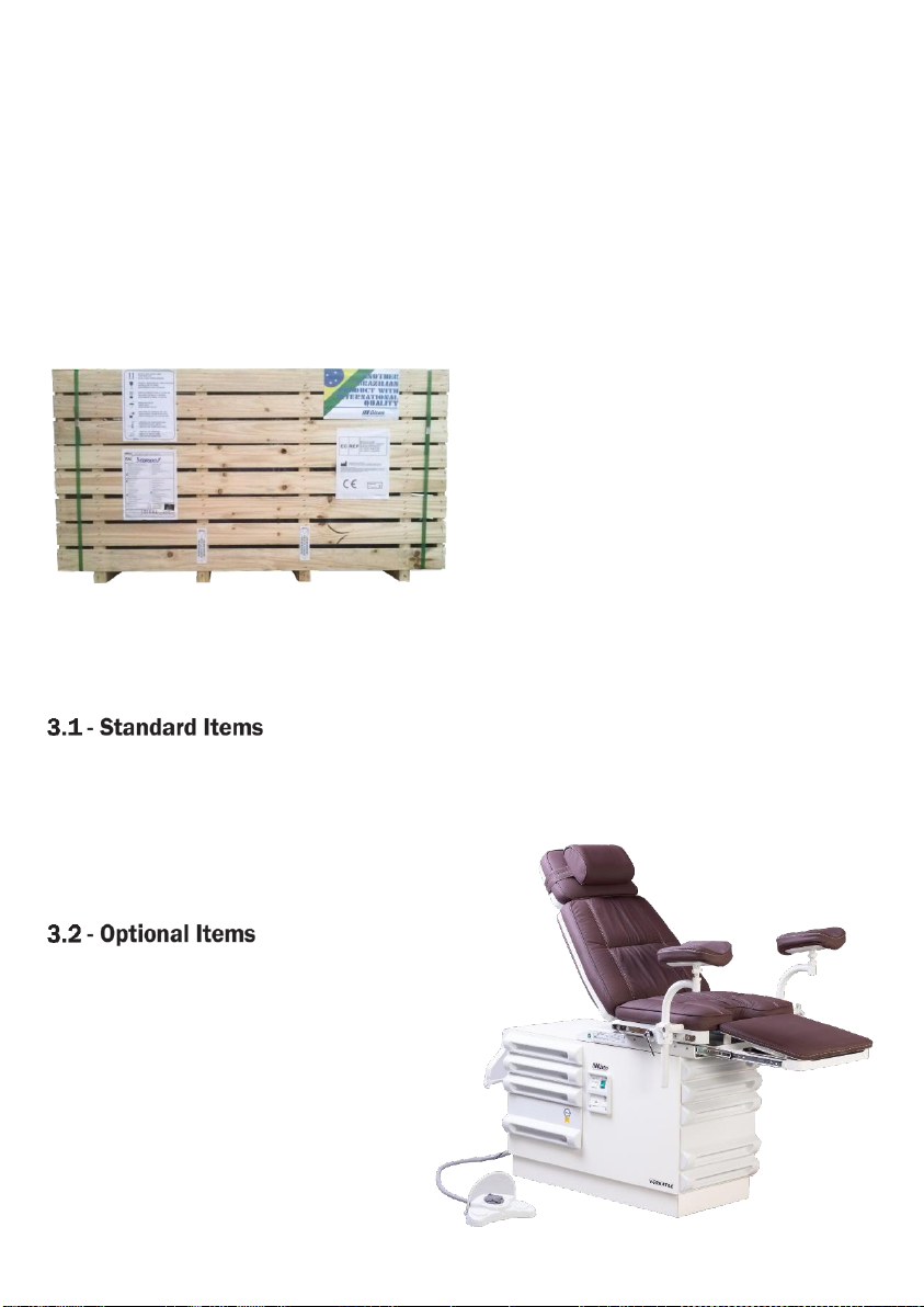
3.1 - Standard Items.............................................................................................................................................5
3.2 - Optional Items ..............................................................................................................................................5
4 - Parts Identification.................................................................................................................................................6
4.1 - Applied Parts ................................................................................................................................................6
4.2 - Accessories and Detachable Parts..............................................................................................................6
5 - Description and Operating of the Equipment .......................................................................................................7
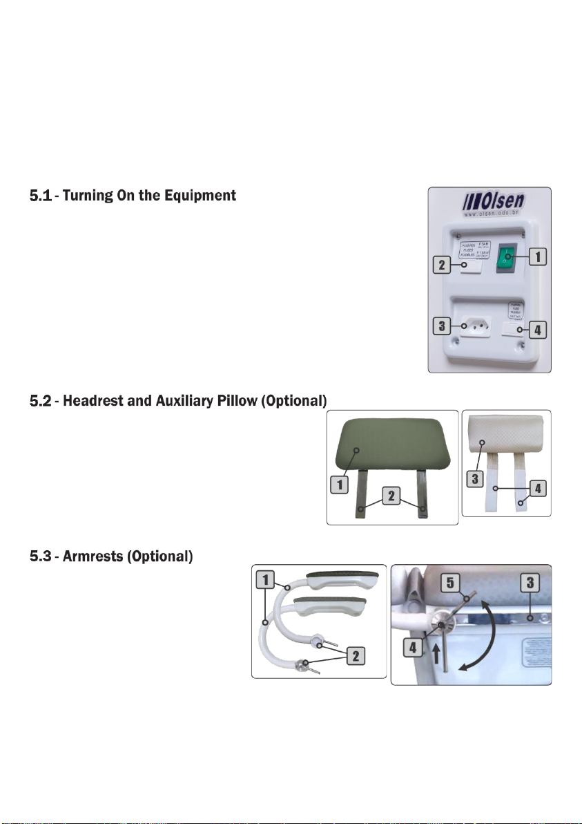
5.1 - Turning On the Equipment...........................................................................................................................7
5.2 - Headrest and Auxiliary Pillow (Optional)......................................................................................................7
5.3 - Armrests (Optional) ......................................................................................................................................7
5.4 - Remote Foot Pedal.......................................................................................................................................8
5.4.1 - Movements Interruption ....................................................................................................................8
5.4.2 - Positioning of the Patient, the Operator and Others.........................................................................8
5.5 - Emergency Position......................................................................................................................................8
5.6 - Paper Roll Holder (Optional) ........................................................................................................................9
5.7 - Sliding Extender ...........................................................................................................................................9
5.8 - Upholstered Leg Rest...................................................................................................................................9
5.9 - Left and Right Bracket Locks.................................................................................................................... 10
5.9.1 - Accessories on Bracket Locks ........................................................................................................ 10
5.10 - Interaction Between Accessories........................................................................................................... 10
5.11 - Double Bracket Locks............................................................................................................................. 11
5.12 - Colposcope Holder (Optional)................................................................................................................. 11
5.13 - Heels Support (Optional) ........................................................................................................................ 11
5.14 - Knees Support (Optional) ....................................................................................................................... 12
5.15 - Retractable Step ..................................................................................................................................... 12
5.16 - Cabinet with 8 Drawers .......................................................................................................................... 12
6 - General Features ................................................................................................................................................ 13
7 - Installation Requirements .................................................................................................................................. 13
7.1 - Pre-installation .......................................................................................................................................... 13
7.2 - Electrical Installation................................................................................................................................. 13
8 - Installation........................................................................................................................................................... 14
8.1 - Position of the Equipment ........................................................................................................................ 14
8.2 - Olsen Certified Technical Assistance Network......................................................................................... 14

9 - Cleaning and Disinfection................................................................................................................................... 14
9.1 - Upholsteries, Plastic Covers and Laminated Parts.................................................................................. 14
9.2 - Painted Parts............................................................................................................................................. 14
9.3 - Sterilization by Autoclave.......................................................................................................................... 15
10 - Technical Features ........................................................................................................................................... 15
10.1 - Electromagnetic Compatibility (EMC)..................................................................................................... 16
11 - Dimensional...................................................................................................................................................... 18
12 - Symbology......................................................................................................................................................... 19
13 - Important Notes................................................................................................................................................ 19
13.1 - General Cares - Compulsory Reading .................................................................................................... 20
13.2 - Disposal................................................................................................................................................... 21
13.3 - Transport and Storage............................................................................................................................ 21
13.4 Contraindication........................................................................................................................................ 21
14 - Troubleshooting................................................................................................................................................ 21
15 - Preventive Review ............................................................................................................................................ 22
16 - Warranty Terms ................................................................................................................................................ 23
17 - Message from the President............................................................................................................................ 24

5
1- Introduction
Congratulations on the great choice!
You have acquired an equipment developed for the outpatient environment, aimed primarily at the
specialty of gynecology, aiming to provide maximum comfort to the patient and facilitate the performance of
procedures by the professional.
This manual is supplemented to the Versatile Quick Operation Guide provided with your equipment and
provides all the information you need to get the most out of your equipment, so read them carefully before using
it.
2- Package Contents
Check out the equipment package contents:
Standard Items:
1 Versatile Table
1 Left Bracket Lock
1 Right Bracket Lock
2 Upholstered Leg Rest
1 Versatile Quick Operation Guide
Optional Items:
1 Auxiliary Pillow
2 Upholstered Armrest
1 Colposcope Holder
1 Heel Support
1 Knee Support
1 Left Additional Bracket Lock
1 Right Additional Bracket Lock
3- Equipment Presentation
Automatic Table with 4 Commands
Headrest
Interchangeable Seat Extension with Built-In Stainless Tray
2 Oil-free Bosch Motors
Upholstered and Interchangeable Leg Rest
Remote Foot Pedal Commands
Retractable Step
Auxiliary Pillow
Upholstered and Interchangeable Armrests
Paper Roll Holder
Colposcope Holder
Heel Support
Knee Support

6
4- Parts Identification
1 -Stainless steel drain pan
2 -Left bracket lock
3 -Seat
4 -Headrest
5 -Paper roll holder
6 -Auxiliary pillow
7 -Backrest
8 -Leg Rest
9 -Extender upholstery
10 -Sliding extender
11 -Front Drawers
12 -Retractable step
13 -Electrical panel
14 -Remote Foot Pedal
15 -Side Drawers
16 -Right Bracket Lock
The following items of the Versatile Table are considered as applied parts to the patient:
Standard Items:
−Upholstery;
−Upholstered ler rest;
−Seat extension;
−Extender upholstery;
Optional Items:
−Auxiliary pillow;
−Upholstery armrests;
−Knee support;
−Heel support.
The following items of the Versatile Table are considered as accessories or detachable parts or:
Standard Items:
−Headrest;
−Upholstered ler rest.
Optional Items:
−Auxiliary pillow;
−Additional left and right bracket locks;
−Upholstered armrests;
−Colposcope Holder;
−Knee support;
−Heel support.

7
5- Description and Operating of the Equipment
Technical Name: Examination Table Trade Name: Versatile Table
The Versatile Table is an automated equipment for patient accommodation on clinical and outpatient
exams and gynecological procedures.
It is equipped with 2 electrical motors to perform 4 individual movements, controlled by remote foot
pedal.
It performs clinical positioning for an emergency condition, allowing brain's irrigation by gravity, with slow
movements to the maximum negative scale (-5° from horizontal). It has retractable step to facilitate the
patient's access to the equipment.
Before starting to use your equipment make sure that it is properly installed, connected to the mains, with
the circuit breaker On and the mains powered.
On the electrical panel, set the On/Off switch (1) to the "I" position. The
switch (1) will light green indicating that the equipment is ready for use.
The electrical panel also it has a fuse holder for equipment (2), an auxiliary
socket (3) and a fuse holder for this socket (4).
To turn Off the equipment: press the On/Off switch (1) to the "O" position.
The headrest (1) was designed to be easily removed
from the backrest according to the procedure need.
It has 2 fixing rods (2) for the fitting.
It can be accompanied by the auxiliary pillow (3) has 2
strips with Velcro®(4) for easy positioning and removal for
cleaning.
The armrests (1) have upholstery in
the same color and characteristics as the
Performance Gyneco Table.
It has adjustable rods (2) that allow
the movements on side rails (3) for depth
adjustment. It can also be used to assist in
patient's lateral containment when he is
lying on the Performance Gyneco Table.
To adjust the armrest (1): pull the
metal lever (5) counterclockwise to loosen it.
Position the armrest (1) and turn the metal lever (5) clockwise to fasten it on the rail.
Note: the metal lever (4) moves only in the area indicated in the above figure. To turn it the metal lever (5)
clockwise, push it upwards causing the lever to pass through the metallic knob's axis (4), and then rotate it
again.

8
The remote foot pedal has the 4 commands of the
Versatile Table identified with symbols that allow an intuitive
operation. Conceived within the latest concepts of ergonomics
and biosafety, it features foot-operated command and metal
handle (5), that allows its drive and movement to be done with
the feet, minimizing the risks of cross contamination.
1 -Seat Up
2 -Seat Down
3 -Backrest Down
4 -Backrest Up
5.4.1 - Movements Interruption
All Versatile Table movements are of continuous activation, i.e., while the operator presses the control
button, the equipment realizes the movement. The movement is interrupted immediately when the operator
releases the control button.
5.4.2 - Positioning of the Patient, the Operator and Others
During the equipment movement, the operator and other persons close to him/her should position
themselves on the equipment sides, respecting the minimum distance of 50 centimeters, remaining out of the
equipment movement area and its components.
To ensure safe and proper patient positioning, the operator should advise him to keep his hands in sight
during the entire equipment movement on the equipment upholstery or on the specific accessories for
performing the procedure. If the operator sees any situation that may generate any kind of risk to the patient,
the chair must be stopped immediately.
All equipment automatic movements must be supervised by the operator.
All equipment’s automatic movements must be supervised by the operator. If the operator sees any
situation that may generate any kind of risk to the patient, the chair must be stopped immediately.
The presence of the operator, persons or objects in the equipment movement areas and its
components may cause damage to the equipment and/or impair its correct operation.
Press the Backrest Down command (section 5.4) in
the remote foot pedal, until the end of the course. The
equipment will adjust the backrest position in -5º related to
the floor.
The seat can be raised for lifting lower limbs.

9
Positioned on the back
side of the cabinet, this holder
can be use with rolls up to
100 mm in diameter.
To put the sheet roll on
the holder: turn the holder's
shaft (1) clockwise, by pulling
it in the opposite direction to
the backrest. No need to
remove the 2 shaft ends. Just
remove 1 side only to put the
disposable sheet roll.
Note: the roll of disposable sheet is not included.
Located under the seat, it offers alternatives to facilitate the procedures through the extender
upholstery (1) and stainless-steel tray (4). Both can be easily removed for cleaning and the tray can be sterilized
by steam autoclave.
To use these items: pull the sliding extender (2) until its structure engages on the latches (3).
To use the stainless tray (4): remove the extender upholstery (1).
To use the upholstery (1): position it on the latches (3).
To retract the sliding extender (1): position the extender´s tray (4) and upholstery (1) in its compartments
and push the sliding extender (2) up to the end of the stroke.
Manufactured with the same upholstery of the Versatile Table, they feature soft foam to provide greater
comfort to the patient. With the aid of the bracket locks, the upholstered leg rest (1) feature height and depth
adjustment.
The leg rest features upholsteries (1) fitted on the metal support (2), allowing a free spin on the fitting
shaft (3).
The fitting shaft has joint (4), which gives the piece the inclination adjustment.
To adjust the inclination: position the upholstery on the requested position.

10
Used for attaching accessories to the side
rails. They are identified according to the side of the
seat to be installed. The bracket lock for the left
side (1) receives the letter “L” and the right one (2)
receives the letter “R”.
To adjust the height (6) or turning (7) of the
accessory, turn the plastic handle (3)
counterclockwise. Adjust the accessory to the desired position and
tighten the plastic handle (3) by turning it clockwise.
To adjust the position of the rails (8), pull the metal lever (4)
counterclockwise by loosening the bracket on the side rail. Adjust
the accessory to the desired position and turn the metal lever (4)
clockwise.
Note: the metal lever (4) moves only in the area indicated in the
figure to the side. To turn it the metal lever (4) clockwise, push it
upwards causing the lever to pass through the metallic knob's
axis (5), and then rotate it again.
5.9.1 - Accessories on Bracket Locks
Accessories which can be installed on the Versatile Table by using bracket locks:
Through the left and right bracket locks,
these accessories can be adjusted in
height, depth and rotation on the axis.
The Versatile Table allows the attendance of patients both lying down
and sitting. In each of these conditions, the installation of the accessories to
the side rails must be carefully observed to avoid damages to procedures,
equipment and patient.
When moving the equipment, ensure that the accessories do not collide
with one another or with other elements of the equipment, like figure be side.
The positioning of the accessories on the side rails must be made
according to the needs to carry out each procedure, but the interaction
between the accessories, during the equipment´s movement it´s operator´s
responsibility.

11
The double bracket locks allow the coupling of 2
accessories, taking up less space on the side rails. The
plastic handles (1) allow height and rotation on the
shaft (distance the accessory to seat) adjustment,
while the metallic lever (3) allows the bracket lock
adjustment on the side rails.
Simply turn counterclockwise to loosen and
clockwise to lock.
To adjust the bracket locks position on the side rail, pull the metal lever (3) counterclockwise. Adjust the
attachment to the desired position and press the metal lever (3) clockwise.
Note: the metal lever (3) moves only in the area indicated in the figure above. To turn it the metal lever (3)
clockwise, push it upwards causing the lever to pass through the metallic knob's axis (2), and then rotate it
again.
The Colposcope holder is attached to the metal support (4) of
the upholstered leg rest or knee support, optimizing the
professional's work space. This accessory can receive Colposcopes
with pin fitting up to 22.5 mm diameter (7/8").
It has arm (3) with free joint, allowing better positioning of the
Colposcope (5).
To attach the Colposcope: fit it and turn the knob (1)
clockwise by locking it in the desired position.
To adjust the height (6): turn the knob (2) to loosen the regulatory bar, place the Colposcope at the
requested height and turn the knob (2) clockwise to lock in position.
They offer support for the heels and are available with double bracket locks (3) that allow the
simultaneous fixation of the heels support (1) and the leg (section 5.8) rest or knees support (section 5.14).
The heels support (2) can be adjusted for height, heel pads position and movement on the side rails.
In addition to bracket locks adjustments, heel supports (2) can be adjusted for the heel pad distance
according to the patient profile or procedure to be
performed.
To fix the heel
support (2): fit the
support (2) into the
holes (4) along the metal
support (1) according to
the desired distance.

12
They allow patient's accommodation with bent legs, providing
more space to perform procedures. With the bracket locks is
possible to adjust the knee support height and the depth.
Covered with non-slip coating, it assists in the patient's boarding and
allows the professional to better approach the equipment since the step (1)
can be repositioned inside the cabinet.
For the professional to have all the material
needed at your fingertips, the Versatile Table offers
8 drawers with different sizes, 4 drawers under the
seat and 4 drawers on the right side of the
equipment.

13
6- General Features
−Upholsteries: are assembled on a very resistant frame, with soft foam and coated with flexible laminated
PVC or leather, which besides being resistant, providing easy asepsis for the whole.
−Mechanical structure: manufactured in SAE 1020 rolled steel profiles and welded by MIG process, to
guarantee the strength and durability.
−Electrostatic painting: it is applied to all structural metal parts of the equipment. The special
polyurethane paint provides the equipment with high durability coating and has antibacterial
properties according to JIS Z 2801: 2000, where in 24 hours, the bacterial reduction is greater than
99.9%.
−Plastic covers: made of high-strength ABS with acrylic cover, the plastic covers do not require painting
and allowing polishing for recovery in case of wear or scratches.
−Electrical system: the equipment can work in frequencies of 50 or 60 Hz and can be configured to be
connected to the voltages of 118/127/220/230 Volts by an authorized technician. The maximum
supply voltage of electronic boards, motors, and other controls is 24 V. The electrical system has
On/Off switch and protection fuses.
−Spindle drive motor: all motors used in the equipment are produced by Robert Bosch of Brazil and have
advantages such as low noise, the absence of oil reservoir, uniformity in displacement, reduction of
energy consumption and low cost for maintenance. The motors also have protection systems that act
on the mechanical and electrical parts of the set.
−Pressurized suspension: the high pressure nitrogen cylinder relieves the load of the gear motor lifting
system of the equipment in 100 kg. This means that a patient with this approximate weight is not
acting on the electromechanical lifting components.
−Cabinet made of MDF (Medium Density Fiberboard): the cabinet and its drawers are made of MDF and
laminated coating, providing asepsis easiness and better finishing.
7- Installation Requirements
The pre-installation must be guided by the Olsen authorized service to ensure that the environment is
adequate the specified requirements for operation of the equipment (see chapter 8) and the positioning in
which it is to be used. In this step the electrical connections and, if necessary, all the water and sewage pipes,
according to the equipment's options, must be prepared.
This equipment is not designed to be installed or operated in a surgical center.
The power grid must be single-phase, has specific grounding and 10 A/3 mA DR circuit breaker. The
circuit breaker must exclusively supply for the Versatile Table and must be easy and quick to disconnect from
the mains. If the power grid presents voltage variation, the installation of a surge protection device is required.
The power switch must be turned off at the end of the workday.
There is a table below for sizing the electrical installation:
Tension (V)
Wire Diameter (mm2)
Distance (m)
Current (A)
118/127/220/230
2,5
20
5,0
This equipment should only be connected to a power source with protective grounding. There is a
risk of electric shock!

14
8- Installation
The Versatile Table installation must be done by Olsen certified technician consists in assembling legs
rest and checking the mains voltage which will supply the equipment and, if necessary, make the tension
adjustment. In the case of optional items have been purchased, these should also be installed at this time.
The technician will also verify if the equipment complies with the purchasing order, if it maintains its
integrity, and will provide operation, cleaning and maintenance guidance.
When the installation is complete, observe the following items:
−Both right and left bracket locks are installed with the upholstered leg rest;
−All remote foot pedal commands work perfectly;
−The sliding extender has the stainless-steel tray and the upholstery and slides perfectly;
−The upholsteries of backrest, seat, headrest and legs rest are intact.
In the case of optional items have been purchased, check the items below according to the acquired
optional item:
−The armrests are installed on the side rails;
−The Colposcope holder was installed and performs all the joints perfectly;
−The knee supports were installed on their respective bracket locks;
−The heel supports were installed on their respective bracket locks;
−Integrity of upholstery and finishes;
−Joints without rigidity when moving;
−The fitting of accessory is secure.
For instructions on the proper functioning of the equipment and its components, read Chapter 5
(Description and Operating of the Equipment) of this manual.
Installation should only be made by an authorized technician. Installation performed by an
unauthorized person will result in loss of warranty.
To position the equipment, put the backrest parallel to the floor and pull the sliding extender and the
retractable step until your limit, and then bring the equipment to where it will be used. Carry out the up and
down movements of the backrest as well as open and storing the sliding extender and the retractable step,
making sure that there is enough space for all movements.
To access the Olsen certified technical assistance network for installation and maintenance contact us by
e-mail export3@olsen.odo.br or if you prefer +55 48 2106 6000.
9- Cleaning and Disinfection
The whole sanitize process must be done with the use of gloves suitable for cleaning and
protection, in addition to a mask and protective glasses, according to biosafety standards.
The upholsteries, plastic covers and laminated parts must be cleaned with a damp cloth containing
neutral soap or detergent only. Olsen advises against using any chemical product to clean these parts, but in the
case of disinfection products, it is important to check if it has suitable compatibility and specifications before
use on these materials.
Never use hypochlorite or alcohol-based products.
It must be cleaned with a slightly damp cloth containing only soap or mild detergent.
Never use hypochlorite or alcohol-based products.

15
The stainless steel tray can be sterilized by steam autoclaving at the following values (sterilization
according to SS-374 Resolution of 12/15/1995 and ISO 17665):
a) 130º C,2 bar,15minutes;
b) 120º C, 1 bar,30minutes;
c) 134º C, 2,2 bar, 4 minutes.
Note: these items withstand up to 1.000 autoclaving cycles.
All equipment items mentioned in this chapter must be sanitized and sterilized (when appropriate)
prior to use.
Olsen is not responsible for defects, deformities, stains or abnormalities caused by improper use of
chemical products, contact with tissues, leather, disposable gloves, inks, pigmented detergents
and other organic or synthetic products.
10 - Technical Features
Power supply: 118/127/220/230 VC~.
A certified technician when installing the equipment must select the voltage;
Note: all equipment is adjusted in the factory to 220 VC~.
Number of phases: single phase. Frequency: 50/60 Hz.
Power 118/127 V: 200 VA. Power 220/230 V: 250 VA.
Protection fuses:
−For 220/230 VC~: 1,5 A H (5 x 20 mm).
−For 118/127 VC~: >3 A H (5 x 20 mm).
Power cable specification (in compliance with requirements 6.1 and 6.2 of IEC 60601-1-2:2010):
−Flexible Cable PP Circular 500 V 3 x 1 mm 247-5 NM 53-C5.
−Tri-polar Male Plug 10 A - 250 V (NBR 14136).
Electrical shock protection type: Class I equipment, according to IEC 60601-1-1 and IEC 60601-1-2 standards.
Protection degree: B Type;
Operation mode: non-continuous.
Time On: 30 s. Time Off: 5 min.
Operating environment conditions:
−Temperature: between 15º and 30º C.
−Relative humidity: 30% to 70% non-condensing.
−Pressure: 75 kPa to 106 kPa.
Harmful water penetration’s protection:
−Equipment: IPX0.
−Remote Pedal: IPX1.
Thermal protection of the transformer: aperture with 130º C ± 3%.
Lifting capacity (maximum patient weight + accessories): up to 200 kg.
Equipment weight:
−Net: 140,9 kg (with accessories: 155,2 kg).
−Gross: 179,9 kg (with accessories: 194,2 kg).
The weight of accessories:
−Armrest: 3,5 kg.
−Upholpery leg rest: 4,20 kg.
−Colposcope holder: 2,90 kg.
−Heel support: 5,10 k.
−Knee support: 4,20 kg.

16
The Versatile Table needs special attention regarding electromagnetic compatibility and must be
installed and put into use in accordance with the electromagnetic compatibility information
presented in this chapter.
Radio frequency (RF) communication equipment, portable and mobile, can affect the Versatile
Table.
Guidance and Manufacturer's Declaration - Electromagnetic Emissions
The Versatile Table is intended for use in the electromagnetic environment specified below. The customer or the user should
assure that it is used in such an environment.
Emission test
Compliance
Electromagnetic Environment - Guidance
RF emissions
CISPR 11
Grupo 1
The Versatile Table uses RF energy only for its internal function.
Therefore, its RF emissions are very low and are not likely to
cause any interference with nearby electronic equipment.
RF emissions
CISPR 11
Class B
The Versatile Table is suitable for use in all establishments,
including domestic establishments and those directly connected
to the public low-voltage power supply network that supplies
buildings use for domestic purposes.
Harmonic emissions
IEC 61000-3-2
Non-applicable
Emissions due to voltage
fluctuations/scintillation
emissions
IEC 61000-3-3
Non-applicable
Guidance and Manufacturer's Declaration - Electromagnetic Emissions - I
The Versatile Table is intended for use in the electromagnetic environment specified below. The customer or the user should
assure that it is used in such an environment.
IMMUNITY Test
IEC 60601 Test Level
Compliance Level
Electromagnetic Environment Guidance
Electrostatic discharge
(ESD)
IEC 61000-4-2
± 6 kV contact
± 8 kV air
± 6 kV contact
± 8 kV air
Floors should be wood, concrete or
ceramic file. If floors are covered with
synthetic material, the relative humidity
should be at least 30%.
Electrical fast
transient/burst
IEC 61000-4-4
± 2 kV for power supply
lines
±1 kV for input/output
lines
± 2 kV for power supply
lines
±1 kV for input/output
lines
Mains power quality should be that a
typical commercial or hospital
environment.
Surge
IEC 61000-4-5
± 1 kV differential mode
± 2 kV common mode
± 1 kV differential mode
± 2 kV common mode
Mains power quality should be that a
typical commercial or hospital
environment.
Voltage dips, short
interruptions and
voltage variations on
the power supply
input lines
IEC 61000-4-11
<5% UT(dip > 95% in UT)
for 0.5 cycle
40% UT(60% dip in UT)
for 5 cycles
70% UT(30% dip in UT)
for 25 cycles
<5% UT(dip > 95% in UT)
for 5 s
<5% UT(dip> 95% in UT)
for 0.5 cycle
40% UT(60% dip in UT)
for 5 cycles
70% UT(30% dip in UT)
for 25 cycles
<5% UT(dip> 95% in UT)
for 5 s
Mains power quality should be that of a
typical commercial or hospital
environment. If the user of the Versatile
Table requires continued operation during
power mains interruptions, it is
recommended that the Versatile Table be
powered from an uninterruptible power
supply or a battery.
Power frequency
(50/60 Hz) Magnetic
field
IEC 61000-4-8
3 A/m
3 A/m
Power frequency magnetic fields should
be at levels characteristic of a typical
location in a typical commercial or
hospital environment.
NOTE UTis the a.c. mains voltage prior to applications of the test level.

17
Guidance and Manufacture’s Declaration - Electromagnetic Immunity
The Versatile Table is intended for use in the electromagnetic environment specified below. The customer or the user should
assure that it is used in such an environment.
IMMUNITY Test
IEC 60601 Test Level
Compliance
Level
Electromagnetic Environment - Guidance
Conducted RF
IEC 61000-4-6
Radiated RF
IEC 61000-4-3
3 Vrms
150 kHz to 80 MHz
3 V/m
80 MHz to 2,5 GHz
3Vrms
3 V/m
Portable and mobile RF communications equipment should
not be used closer to any part of the Versatile Table,
including cables, than the recommended separation
distance calculated by the equation applicable to the
transmitter frequency.
Recommended separation distance
80 MHz to 800 MHz
800 MHz to 2,5 GHz
Where Pis the transmitter maximum output power rating in
watts (W) according to the transmitter manufacturer and d
is the recommended separation distance in meters (m).
Field strengths from fixed RF transmitters, as determined
by an electromagnetic site survey a, should be less than
the compliance level in each frequency range. b
Interference may occur in the surroundings of equipment
marked with the following symbol:
NOTE 1 At 80 MHz and 800 MHz, the higher frequency range applies.
NOTE 2 These guidelines may not apply in all situations. Electromagnetic propagation is affected by absorption and reflection
from structures, objects, and people.
a
b
Field strengths from fixed transmitters, such as base stations for radio (cellular/cordless) telephones and land mobile
radios, amateur radio, AM and FM radio broadcast and TV broadcast cannot be predicted theoretically with accuracy.
To assess the electromagnetic environment due to fixed RF transmitters, an electromagnetic site survey should be
considered. If the measure filed strength in the location in which the Versatile Table is used exceeds the applicable RF
COMPLIANCE LEVEL above, the Versatile Table should be observed to verify normal operation. If abnormal
performance is observed, additional measures may be necessary, such as reorienting or relocating the Versatile Table.
Over the frequency range 150 kHz to 80 MHz, field strengths should be less than 3 V/m.
Recommended Separation Distances Between Portable and Mobile RF
Communications Equipment and the Versatile Table
The Versatile Table is intended for use in an electromagnetic environment in which radiated RF disturbances are controlled. The
customer or the user can help prevent electromagnetic interference by maintaining a minimum distance between portable and
mobile RF communications equipment (transmitters) and the Versatile Table as recommended below, according to the
maximum output power of the communications equipment.
Rated Maximum Output
the Power of the Transmitter
(W)
Separation Distance According to Frequency of Transmitter (m)
150 kHz to 80 MHz
80 MHz to 800 MHz
800 MHz to 2,5 GHz
0,01
0,12
0,12
0,23
0,1
0,37
0,37
0,74
1
1,2
1,2
2,3
10
3,7
3,7
7,4
100
12
12
23
For transmitters rated at a maximum output power not listed above, the recommended separation distance d in meters (m) can
be estimated using the equation applicable to the frequency of the transmitter, where P is the maximum output power rating of
the transmitter in watts (W) according to the transmitter manufacturer.
NOTE 1 At 80 MHz and 800 MHz, the separation distance for the higher frequency range applies.
NOTE 2 These guidelines may not apply in all situations. Electromagnetic propagation is affected by absorption and reflection
from structures, objects, and people.

18
11 - Dimensional

19
12 - Symbology
The symbology complies with standards IEC 60601-1 and IEC 60878.
13 - Important Notes
The reproduction and distribution of these instructions can only be made with prior permission from Olsen
Indústria e Comércio S.A.
The technical features of the products described in this manual correspond to the time of its publication.
Future technical improvements do not result in any right to update existing products.
The images presented in this manual are illustrative.
This equipment is designed to be free from interference from magnetic fields, external electrical
influences, electrostatic discharges, pressure or pressure variation, provided that the equipment is transported,
installed, operated and sanitized in accordance with the instructions for use contained in this manual.
The estimated useful life of this equipment is 5 years.

20
Follow the instructions in chapter 7 of this manual (Installation Requirements) to suit the electrical
network where the equipment will be installed.
Follow instructions for proper use of the equipment and its accessories as described in chapter 5
(Description and Operating of the Equipment). Improper use could be harmful to equipment, which
would not be covered by warranty.
Follow the instructions in chapter 9 (Cleaning and Disinfection) of this manual for daily cleaning of
your equipment.
Protect your equipment from direct exposure to sunlight. The equipment direct exposure to sunlight
may cause premature aging of plastic covers and upholstery.
Turn off the circuit breaker or unplug the equipment at the end of the working day.
In case of remote foot pedal damage, discontinue use of the equipment, turn it off, and contact
Olsen accredited assistance.
The electric mains cable was developed for use only on the Versatile Table. The use of this
component in other equipment may compromise the emissions and electromagnetic immunity of
these.
Only the authorized technician can replace the equipment´s mains cable and internal fuses.
This equipment is not suitable for use in the presence of a flammable anesthetic mixture with air, O2
or Nitrous Oxide.
This equipment should only be operated by physicians and nurses for clinical, outpatient, and
gynecological procedures.
Use only the mains cable supplied with the equipment for mains connection. Use of cables other
than those specified (chapter 10 - Technical Features) may result in increased emissions or reduced
immunity of the Versatile Table.
Do not remove the plastic covers from the equipment. The risk of electric shock! Only the accredited
technician is authorized to perform this procedure.
In the case of damage to the electrical panel, adjacent plastic covers and motors plastic covers
disconnect the equipment from the mains and contact the Olsen accredited service. The use of the
equipment must be interrupted until maintenance is complete. The use of the equipment in these
conditions offers a risk of electric shock!
Do not perform maintenance or cleaning on the Versatile Table while it is in use or turned On.
Do not install or use any electrical equipment over or near the Versatile Table. If necessary, the
Versatile Table must be checked to see if it is functioning normally in the configuration in which it
will be used.
Do not perform fuse replacement if it is possible to touch the patient, even if unintentionally, during
the procedure.
This manual suits for next models
1
Table of contents
Languages:
Other Olsen Medical Equipment manuals
Popular Medical Equipment manuals by other brands

DeVilbiss
DeVilbiss iGo Equipment manual

Welch Allyn
Welch Allyn CSM 7100 Service and Repair Training

myHummy
myHummy MS01 user manual

Precor
Precor Cardio Theater Integrated Bracket Assembly Instructions EFX... Assembly instructions

Gi
Gi Paragon 203 quick start guide

SELVAS Healthcare
SELVAS Healthcare ACCUNIQ BP210 user manual