Outdoor Living Today www.outdoorlivingtoday.com sales@outdoorlivingtoday.com
Page 4
Note: Trim and Skirting pieces are graded with the best face being rough sawn.
Rough sawn cedar is much easier to paint and stain.
Thank you for purchasing our 6x3 Garden Saver.
Please take the time to identify all the parts prior to assembly.
Parts List
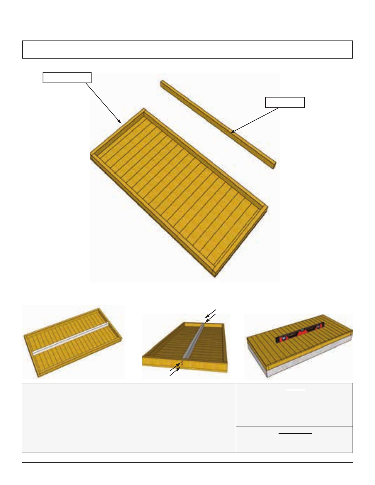
A. - Floor Section
Floors
1 - Floor Section - 35” x 73”
1 - Mid Floor Joist - 1 1/2” x 2 1/2” x 70”
Steps
1
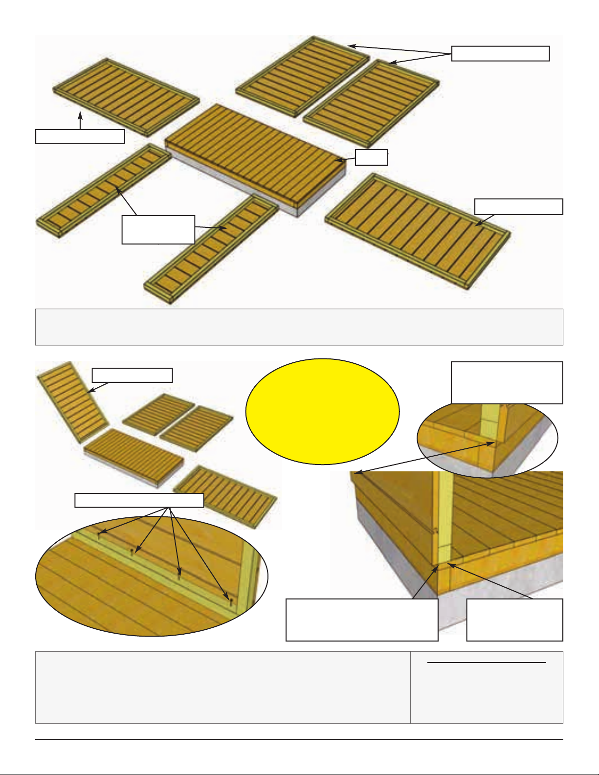
B. - Wall Section
Main Wall Panels
4 - Rear/Side Walls - 35” x 63 1/4” - Identical
4 - Top Wall Plates - 1 1/2” x 1 1/2” x 35”
2 - Front Narrow Walls - 12 1/2” x 61 3/4” - Identical
Header/Wall Extenders
1 - Front Header - 1 1/2” x 1 1/2” x 70”
1 - Interior Door Header - 1 1/2” x 1 1/2” x 44 7/8”
2 - Left/Right Side Angle Gables - 6 1/2” x 35”
2 - Wall Extenders - 6 1/4” x 35”
1 - Rear Top Plate - 1 1/2” x 1 1/2” x 70”
Shelves
Storage Shelf Supports
Short (2 - 3/4” x 2 1/2” x 12 1/2”)
Long (2 - 3/4” x 2 1/2” x 35”)
2 - Storage Shelves - 11 1/2” x 31 7/8"
2 - 11
12 - 23
24 - 25
C. - Roof Section
Roof
1 - Cedar Shingle Roof Panel - 38 3/4” x 78 1/4”
26 - 27
D. - Trim / Misc. Section
Lower Skirting
2 - Lower Rear Skirting - 1/2” x 2 1/2” x 35”
2 - Lower Side Skirting - 1/2” x 2 1/2” x 33”
Lower Front Skirting
Short (2 - 1/2” x 2 1/2” x 11 1/8”)
Long (1 - 1/2” x 2 1/2” x 47 1/4”)
Filler Trim
8 - Front/Rear Filler Trims - 5/8” x 1 1/2” x 30”
1 - Front Header Filler Strip - 5/8” x 1” x 69 1/2”
1 - Rear Top Plate Filler Strip - 5/8” x 1 1/2” x 69 1/2”
29
30 - 33
D. - Trim / Misc. Section Cont.
Outer Wall Trim and Fascia
1 - Upper Front Horizontal Trim - 1/2” x 2 1/2” x 74 1/4”
2 - Side Fascia Trims - 1/2” x 2 1/2” x 37 5/8” - Angle Cut
Ends
2 - Front Wide Corner Trims - 1/2” x 3 1/2” x 70 3/8”
2 - Front Side Corner Trims - 1/2” x 2 1/2” x 70 3/8” - Angle
Cut End
2 - Rear Wide Corner Trims - 1/2” x 3 1/2” x 67 3/4”
2 - Rear Side Corner Trims - 1/2” x 2 1/2” x 65 1/2” - Angle
Cut End
1 - Upper Rear Horizontal Trim - 1/2” x 2 1/2” x 67 1/4”
1 - Rear Center Trim - 1/2” x 2 1/2” x 65 1/8”
2 - Vertical Door Frame Trim - 1/2” x 2 1/2” x 64 1/4”
Door System
1 - Door Threshold (Bevel) - 1/2” x 2 5/8” x 44 7/8”
2 - Left/Right Doors - 22 1/4” x 61 3/8”
1 - Door Flange - 1/2” x 2 1/2” x 61 3/8”
4 - Interior Vertical Door Stops - 3/4” x 3/4” x 29 7/8”
Miscellaneous
1 - Front Horizontal Trim - 1/2” x 3” x 67 1/4”
1 - Metal Drip Edge - 60”
1 - Front Middle Trim - 1/2” x 2 1/2” x 2 5/8"
2 - Roof Ridge Caps - 1/2” x 3 1/2” x 39 1/4”
** Plus 2 Cedar Shingle Shims - discard after shimming
doors
Steps
34 - 41
42 - 54
55 - 57
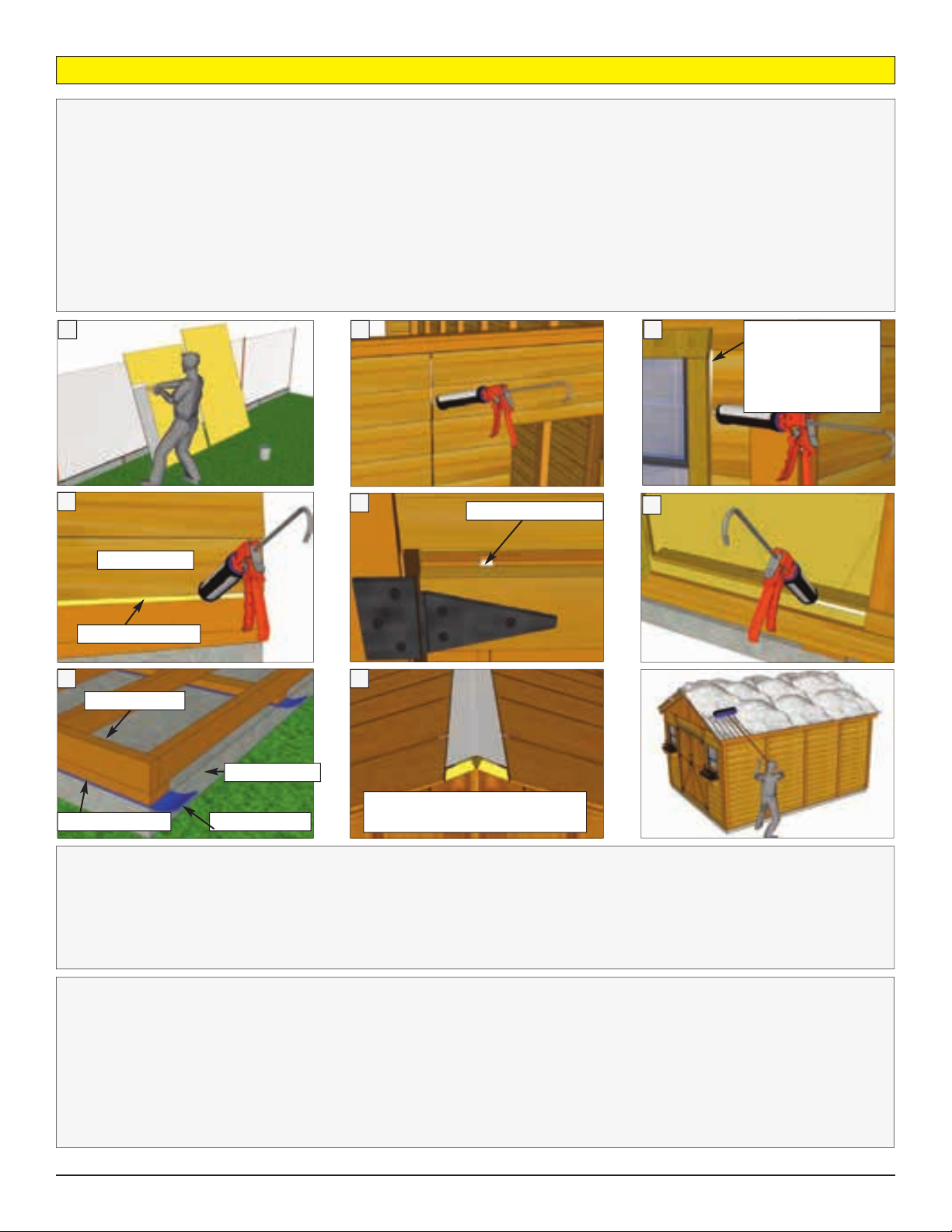
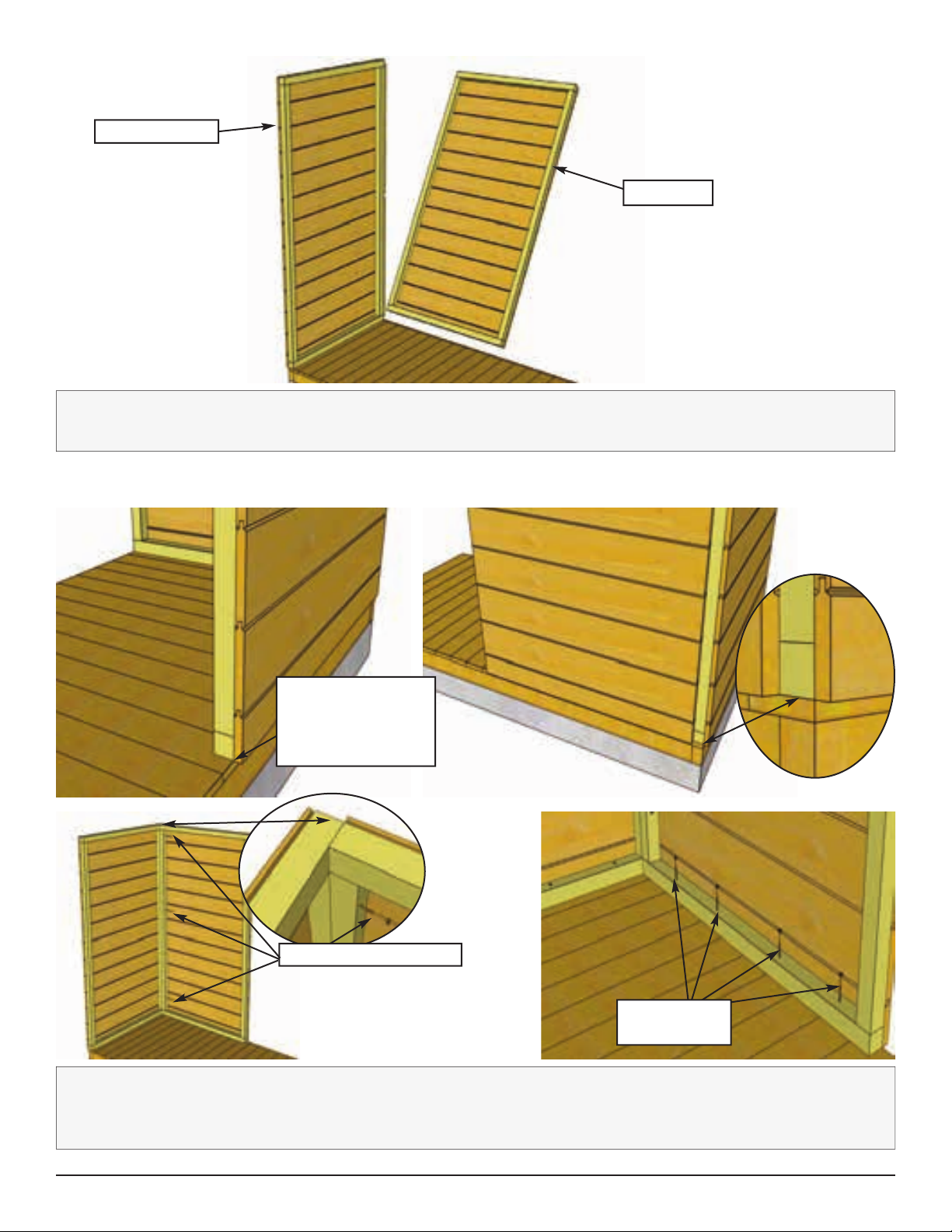
Note: We recommend you drill a 1/8” pilot hole for each
screw to avoid splitting wood. The hole depth should be
equal to 3/4 the length of screw.