Outdoor Living Today www.outdoorlivingtoday.com sales@outdoorlivingtoday.com
Page 4
Thank you for purchasing our 6x4 Space Master with Metal Roof.
Please take the time to identify all the parts prior to assembly.
Note: Trim and Skirting pieces are graded with the best face being rough sawn.
Rough sawn cedar is much easier to paint and stain.
Parts List
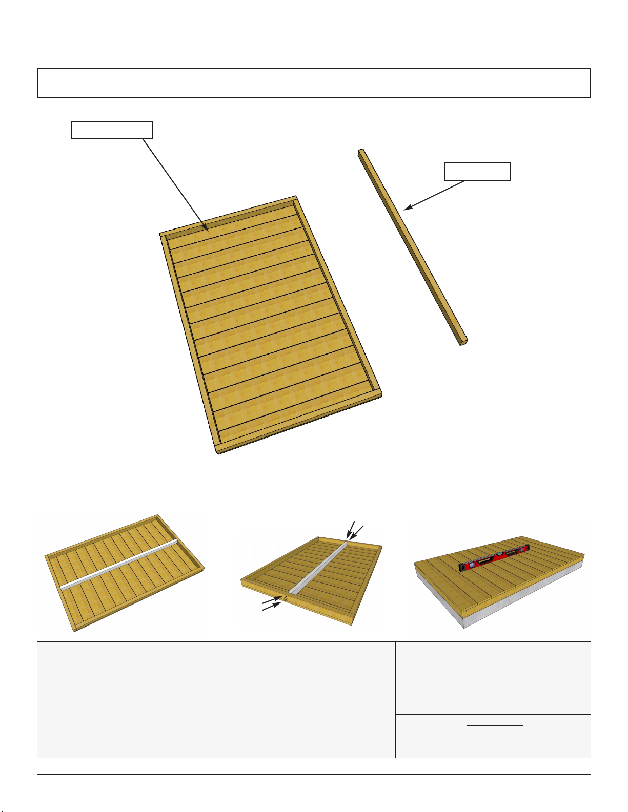
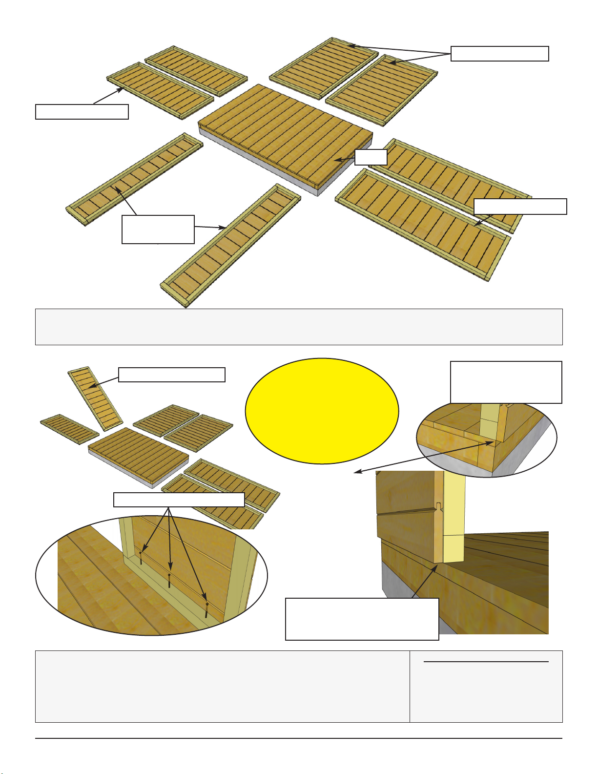
A. - Floor Section
Floors
1 - Floor Section - 45” x 73”
1 - Mid Floor Joist - 1 1/2” x 2 1/2” x 70”
Steps
1
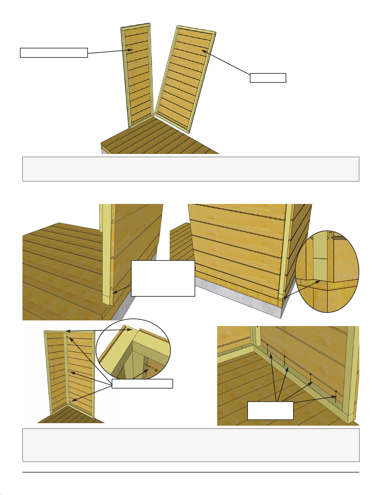
B. - Wall Section
Main Wall Panels
2 - Rear Walls - 35” x 63 1/4”
4 - Side Walls - 22 1/2” x 63 1/4”
2 - Top Wall Plates - 1 1/2” x 1 1/2” x 35”
4 - Top Wall Plates - 1 1/2” x 1 1/2” x 22 1/2”
2 - Front Narrow Walls - 12 1/2” x 61 3/4”
Header/Gables
1 - Front Header - 1 1/2” x 1 1/2” x 70”
1 - Interior Door Header - 1 1/2” x 1 1/2” x 44 7/8”
4 - Front/Rear Top Plate - Sides - 3/4” x 1 1/2” x 19”
2 - Front/Rear Top Plate - Center - 3/4” x 1 1/2” x 32”
2 - Side Wall Top Plates - 3/4” x 1 1/2” x 45” - Angle Cut
2 - Front/Rear Gables - 17 1/2” x 67 3/4”
Shelves
Storage Shelf Supports
Short (2 - 3/4” x 2 1/2” x 12 1/2”)
Long (2 - 3/4” x 2 1/2” x 35”)
2 - Storage Shelves - 11 1/2” x 41 7/8”
2 - 13
14 - 22
23 - 24
C. - Rafters and Roof Section
Roof
4 - Metal Roof Panels - 44”
6 - Rafters - 1 1/2” x 2 1/2” x 41 3/4”
2 - Soffits - 1/2” x 2 1/2” x 45”
2 - Roof Ridge Boards - 3/4” x 3 1/2” X 45”
6 - Battens - 3/4” x 3 1/2” x 49
8 - Batten Spacers - 3/4” x 1 1/2” x 15 5/8”
25 - 45
D. - Trim / Misc. Section
Lower Skirting
2 - Lower Rear Skirting - 1/2” x 2 1/2” x 35 3/4”
4 - Lower Side Skirting - 1/2” x 2 1/2” x 21 3/4”
Lower Front Skirting
Short (2@1/2” x 2 1/2” x 11 3/4”)
Long (1@1/2” x 2 1/2” x 47”)
Filler Trim
8 - Front/Rear Filler Trims - 5/8” x 1 1/2” x 30”
1 - Front Header Filler Strip - 5/8” x 1 1/2” x 69 1/2”
47
48 - 50
D. - Trim / Misc. Section Cont.
Outer Wall Trim and Fascia
4 - Roof Nailing Strips - 3/4" x 1 1/4" x 40"
4 - Front/Rear Wide Corner Trims - 1/2” x 3 1/2” x 67 7/8”
6 - Side Wall Trims - 1/2” x 2 1/2” x 65 1/2”
1 - Rear Horizontal Trim - 1/2” x 3” x 67 1/4”
1 - Rear Center Trim - 1/2” x 2 1/2” x 64 3/4”
4 - Front/Rear Facia - 3/4” x 3 1/2” x 43” - Angle Cut Ends
2 - Side Fascia - 3/4” x 3 1/2” x 49”
2 - Pentagon Detail Plates - 1/2” x 5 1/2” x 8”
2 - Vertical Door Frame Trim - 1/2” x 2 1/2” x 64 1/4”
Door System
1 - Door Threshold (Bevel) - 1/2” x 2 5/8” x 44 7/8”
2 - Left/Right Doors - 22 1/4” x 61 3/8”
1 - Door Flange - 1/2” x 2 1/2” x 61 3/8”
4 - Interior Vertical Door Stops - 3/4” x 3/4” x 29 7/8”
Miscellaneous
1 - Front Horizontal Trim - 1/2” x 3” x 67 1/4”
1 - Metal Drip Edge - 60”
1 - Metal Ridge Cap - 54”
** Plus 2 Cedar Shingle Shims - discard after shimming
doors
Steps
51- 60
61 - 73
74 - 75
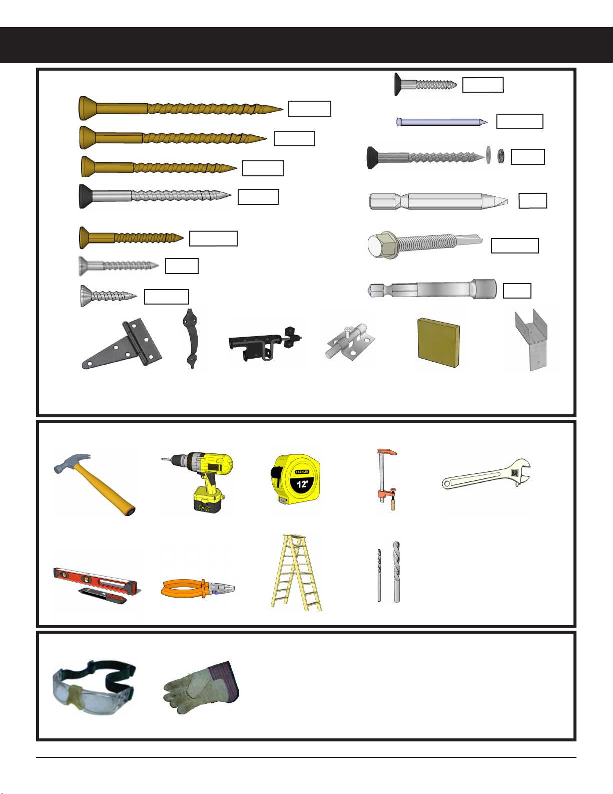
Note: We recommend you drill a 1/8” pilot hole for each
screw to avoid splitting wood. The hole depth should be
equal to 3/4 the length of screw.