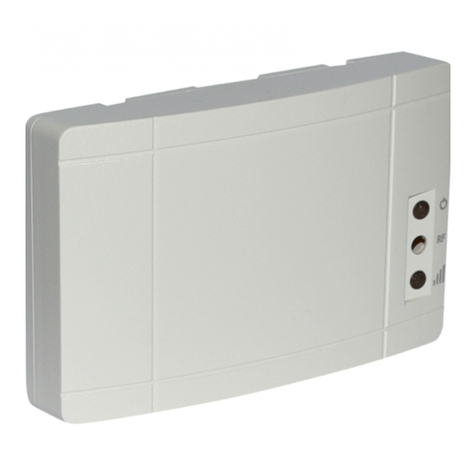
olympia electronics GR-7601 User manual

Page 1 of 4 923760100_09_001
GR-7601 Ethernet Gateway
TECHNICAL CHARACTERISTICS
5 to 40 C
o
ABS/PC
868 - 870MHz
11dBm
-40 to 70 C
o
Up to 95%
2 years
EN 62311:2008, EN 62368-1:2014 +AC:2015,
ETSI EN 301 489-1 V1.9.2, ETSI EN 301 489-3 V1.6.1
ETSI EN 300 220-2 V3.1.1
197gr.
120 x 80 x 34mm
Ambient temperature range
Housing
Storage temperature range
Maximum relative humidity
Dimensions (L x W x H)
Weight
Warranty
Approvals
Operation voltage
Consumption
Tx/Rx frequency range
Tx power
The GR-7601
wireless emergency lighting. It transfers the received data from
the GR-7600 PC Software to the wireless network and vice
versa. One only Gateway can exist in each wireless network.
Ethernet Gateway is the master device of the
Thank you for your trust in our products
Olympia Electronics - European manufacturer
220 - 240 VAC (50 - 60Hz)
2VA
Features:
• Powered from mains 220 - 240VAC
• Status and signal indication LEDs
• Ethernet port (RJ45)
• Webserver
• Fast 868MHz wireless connectivity
Default settings:
• IP: 10.0.1.142
•
• SID: 00000001
• RF Channel: 13 (869.525MHz)
Technician menu password (webserver): 1000
Indications:
: Power On LED (Green).
: RF LED (Orange). Blinking when receiving data from the connected wireless devices
: Signal broadcasting LED (Orange). Blinking indicates Gateway transmissions (beacon).
.
Button functions*:
•
• Long press (>1s and <10s): Reset Gateway.
• Extended press (>10s): Load default settings to the Gateway**.
*The Button is only accessible when the front cover is removed. See schem. 2 - Wiring on page 4.
**Resetting to defaults will restore all changes made by the user to the Gateway, except the SID and
the RF Channel. In order to set SID and RF Channel back to default values, you will have to set the
values manually via the GR-7600 software.
Short press (<1s): Send status message to the Master PC (through Ethernet).
RF

923760100_09_001
Page 2 of 4
Installation:
It’s recommended that the GR-7601 Ethernet Gateway is positioned at a central point of the entire
wireless emergency lighting installation. At least 2 or 3 luminaires should be inside the signal range
of the Gateway in order to create alternative routes for re-transmitting messages to other devices
inside their own range.
See next schematic 1:
Mounting:
Install the device to a stable and visible position which has access to mains power and Local Area
Network (Ethernet). It is recommended that while fitted, the LED indications are visible to a
technician.
Avoid metallic surfaces, as they can affect RF signal strength. Ensure that there is not any severe
RF blocking due to structural design.
Use the 2 mounting holes to fit the base on a vertical wall (concrete/brick/wood) and the embedded
spirit level to make fine (horizontal) adjustments. Tighten the mounting screws when done.
Connect the mains power cables. See Wiring and Dimension schematic in page 4.
Commissioning:
In order to setup the GR-7601 Ethernet Gateway and create a new wireless emergency lighting
network, you will have to follow the following steps:
Connect the onfigure its IP address (via webserver).
Configure the master PC’s IP and MAC address (via webserver).
Run the GR-7600 PC software and setup the new network (Network Configuration Wizard) in
order to modify the SID and the RF Channel of the wireless network and isolate it from other
nearby wireless networks.
See further information regarding configuring IP addresses, master PC’s IP&MAC, etc in the
following page:
GR-7601 to the Local Area Network and c
Schematic 1: Gateway installation plan
Signal route
Wireless luminaries

Page 3 of 4 923760100_09_001
Webserver:
In order to set up the parameters for Gateway - PC Software communication, enter the webserver.
To enter webserver interface, first power on the device, connect the device to the Ethernet network
(RJ45 connector) and then enter the default IP to a common Web Browser via PC
(Chrome/Firefox/etc).
In order to have access to the Gateway, the IPv4 address range must be from 10.0.1.2 to
10.0.1.254, except 10.0.1.142 which is already occupied by the Gateway.
Webserver main screen interface:
In order to set up the master IP, of the PC that runs the GR-7600 PC Software enter “TECHNICIAN
MENU” from the left tab, enter technician code (default: 1000) and then enter “MASTER IP” menu.
Enter the static IP of the PC (3 digit numbers, fill with zeros where needed)
Enter the MAC address of the PC’s Ethernet adaptor (see details in Local Area Network connection
status, Physical address line).
Press “SAVE” to save configurations to the Gateway. The Gateway will now send and receive all the
data regarding the wireless emergency illumination network, to/from this IP.
Via “CHANGE TECH CODE” option you can change the default technician password from 1000 to
another 4 digit number, in order to block access from unwanted sources.
Always enter a 4 digit number. Changing the tech code is an action that should be done responsibly,
as there is no way to restore the default tech code without losing any saved other configurations.

923760100_09_001
Page 4 of 4
Important note:
This device is powered from the mains, so in case of mains interruption it will stop working. If your
wireless network needs to be “alive” during this situation, care should be taken so that the device is
powered by a UPS system.
When the front face is removed in order to access the internal button, do not touch any other areas
other than the button. Live voltage is present to specific areas of the device.
80mm
19mm
120mm 104mm
RF
Mounting Holes
L
KL1
BT1
N
Antenna
Ethernet
RJ45 port
Button
N
L
WARRANTY
Olympia Electronics guarantees the quality, condition and operation of the goods. The period of
warranty is specified in the official catalogue of Olympia Electronics and also in the technical leaflet,
which accompanies each product. This warranty ceases to exist if the buyer does not follow the
technical instructions included in official documents given by Olympia Electronics or if the buyer
modifies the goods provided or has any repairs or re-setting done by a third party, unless Olympia
Electronics has fully agreed to them in writing. Products that have been damaged can be returned to
the premises of our company for repair or replacement, as long as the warranty period is valid.
Olympia Electronics reserves the right to repair or to replace the returned goods and to or not charge
the buyer depending on the reason of defection. Olympia Electronics reserves the right to charge or
not the buyer the transportation cost.
HEAD OFFICE
72nd km. O.N.R. Thessaloniki-Katerini
P.C. 60300 P.O. Box 06 Εginio Pierias Greece
www.olympia-electronics.gr
34mm
Schematic 2: Wiring
Schematic 3: Dimensions
Table of contents
Other olympia electronics Gateway manuals
Popular Gateway manuals by other brands

RAK
RAK WisGate Edge Lite RAK7258 quick start guide

Automated Logic
Automated Logic LGRM-E Technical instructions

Flying Voice Technology
Flying Voice Technology G201N4 user manual

ViewSonic
ViewSonic VCB10 user guide

ETC
ETC Net3 Conductor Setup guide

bihl+Wiedemann
bihl+Wiedemann BWU3593 installation instructions

weintek
weintek cMT-G01 series Installation instructions and parts list

ZyXEL Communications
ZyXEL Communications Prestige 661H Series quick start guide

Compaq
Compaq DECnet SNA Gateway for Synchronous Transport Problem Solving

2N
2N EasyGate Pro user manual

Nortel
Nortel 3050 troubleshooting guide

Telco
Telco Access 211N installation manual