olympia electronics GR-7602 User manual

Page 1 of 5 923760200_09_001
GR-7602 Wifi Gateway
TECHNICAL CHARACTERISTICS
o
5 to 40 C
ABS/PC
868 - 870MHz
11dBm
802.11 b/g/n
WPA2-PSK
18.3 dBm @ 1Mbps DSSS / 13.7 dBm @ 54 Mbps OFDM
o
-40 to 70 C
Up to 95%
2 years
190gr.
120 x 80 x 34mm
Operation temperature range
Construction materials
Storage temperature range
Relative humidity
External dimensions (L x W x H)
Typical weight
Guarantee
Operation voltage
Consumption
Tx/Rx frequency range (wireless emerg. lighting)
Tx power (wireless emerg. lighting)
Wifi connectivity
Wifi security
Tx power (Wi-Fi)
Rx sensitivity (Wi-Fi)
Thank you for your trust in our products
Olympia Electronics - European manufacturer
220 - 240VAC (50 - 60Hz)
2VA
96.0 dBm @ 1 Mbps DSSS / 74.5 dBm @ 54 Mbps OFDM
The GR-7602 Wifi Gateway is a master device of the wireless
emergency lighting network. It transfers the received data from
the GR-7600 PC software to the wireless network and vice
versa.
One only Gateway can exist in each wireless network.
Features:
• Powered from mains 220 - 240VAC
• Status and signal indication LEDs
• Fast 868-870MHz wireless connectivity
• Mini Access Point setup interface
• 2.4GHz IEEE 802.11 b/g/n
• WPA2-PSK
LED indications:
: Power On LED (Green).
: RF LED (Orange) . Blinking when receiving data from the connected wireless devices.
: Signal broadcasting LED (Orange). Blinking indicates Gateway transmissions (beacon).
Button BT1 functions*:
• Short press (<1s): Send status message to the PC Software.
• Long press (>1s and <10s): Reset Gateway.
• Extended press (>10s): Load default settings to the Gateway.
Button BT2 functions*:
• Long press (2s): Establish Mini Access Point (WL Light WiFi). LED LD7 2blinks/s
*The Buttons are only accessible when the front cover is removed. See schem. 2 - Wiring on page 4.
RF
EN 62311:2008, EN 62368-1:2014 +AC:2015,
ETSI EN 301 489-1 V1.9.2, ETSI EN 301 489-3 V1.6.1
ETSI EN 301 489-17 V3.1.1, ETSI EN 300 328 V2.1.1
Produced in accordance with

923760200_09_001
Page 2 of 5
Installation:
It’s recommended that the GR-7602 Wifi Gateway is positioned at a central point of the entire
wireless emergency lighting installation. At least 2 or 3 luminaires should be inside the signal range
of the Gateway in order to create alternative routes for re-transmitting messages to other devices
inside their own range.
See next schematic 1:
Mounting:
Install the device to a stable and visible position which has access to mains power and Wi-Fi
Network. It is recommended that while fitted, the LED indications are visible to a technician.
Avoid metallic surfaces, as they can affect RF signal strength. Ensure that there is not any severe
RF blocking due to structural design.
Use the 2 mounting holes to fit the base on a vertical wall (concrete/brick/wood) and the embedded
spirit level to make fine (horizontal) adjustments. Tighten the mounting screws when done.
Connect the mains power cables. See Wiring and Dimension schematic in page 4.
Schematic 1: Gateway installation plan
Signal route
Wireless luminaries
Important Note:
In order to ensure a stable Wi-Fi connection, check the reception signal level on the area the
GR-7602 is installed, with the help of a Wi-Fi laptop, smartphone, or a special measuring tool.
It’s recommended, for security reasons, to use WPA/WPA2 security with AES/TKIP encryption.
Consult an IT technician for Wi-Fi network configurations when needed.
This device is powered from the mains, so in case of mains interruption it will stop working.
If your wireless network needs to be “alive” during this situation, care should be taken so that the
device is powered by a UPS system.
When the front face is removed in order to access the internal button, do not touch any other areas
other than the button. Live voltage is present to specific areas of the device.

Page 3 of 5 923760200_09_001
To access it, use the Wi-Fi device (PC/Laptop/smartphone) and join the “WL Light WiFi” network.
Once connected, type in the address bar of a web browser, the following page:
captiveportal.net
(or the IP: 192.168.0.50)
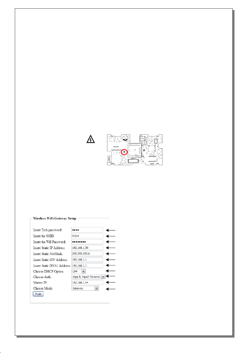
The following page should now appear:
Apply the settings above and click “Push” button. Once the GR-7602 is configured, the mini Wi-Fi
AP will be terminated, then the device will connect to the given Wi-Fi Network (LD7 1 blink/s). This
action may take up to a minute.
DANGER AC
High Voltage
Do not touch
parts/areas
other than
specified
UP: Button BT2 position
Technician password = 1000 (default)
SSID (network name) of the network to join
Target network password
Static IP address for the 290092
Network subnet mask
Network Gateway (router) IP Address
Network DNS Address (empty if not used)
Set DHCP always to OFF
Network security
Pc’s IP Address
Set mode to “Gateway”
Note: values in the fields above are examples and may differ to other networks.
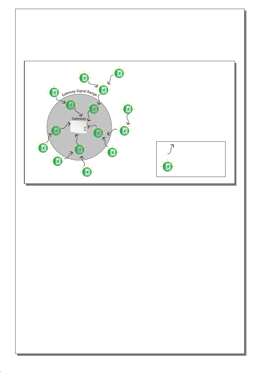
Commissioning:
In order to setup the GR-7602 Wifi Gateway and create a new wireless emergency lighting network,
you will have to follow the following steps:
Establish a mini Wi-Fi Access Point on the GR-7602.
Connect to the mini Wi-Fi Access Point with a Wi-Fi device.
Enter the configuration page to setup Wi-Fi and Master PC connections.
Run the GR-7600 software to continue with commissioning - run Network Config. Wizard to
setup the wireless network for emergency lighting.
For further details see the instructions below:
Wi-Fi connection configuration:
In order for the GR-7602 to communicate with the PC, at least an active Wi-Fi network must be
present and the master (monitoring) PC must be accessible via this network. Activate (power supply)
the device. To connect the device to the existing Wi-Fi, you will need a device with Wi-Fi connectivity
(e.g. smartphone or laptop or tablet), that is set to automatic DHCP.
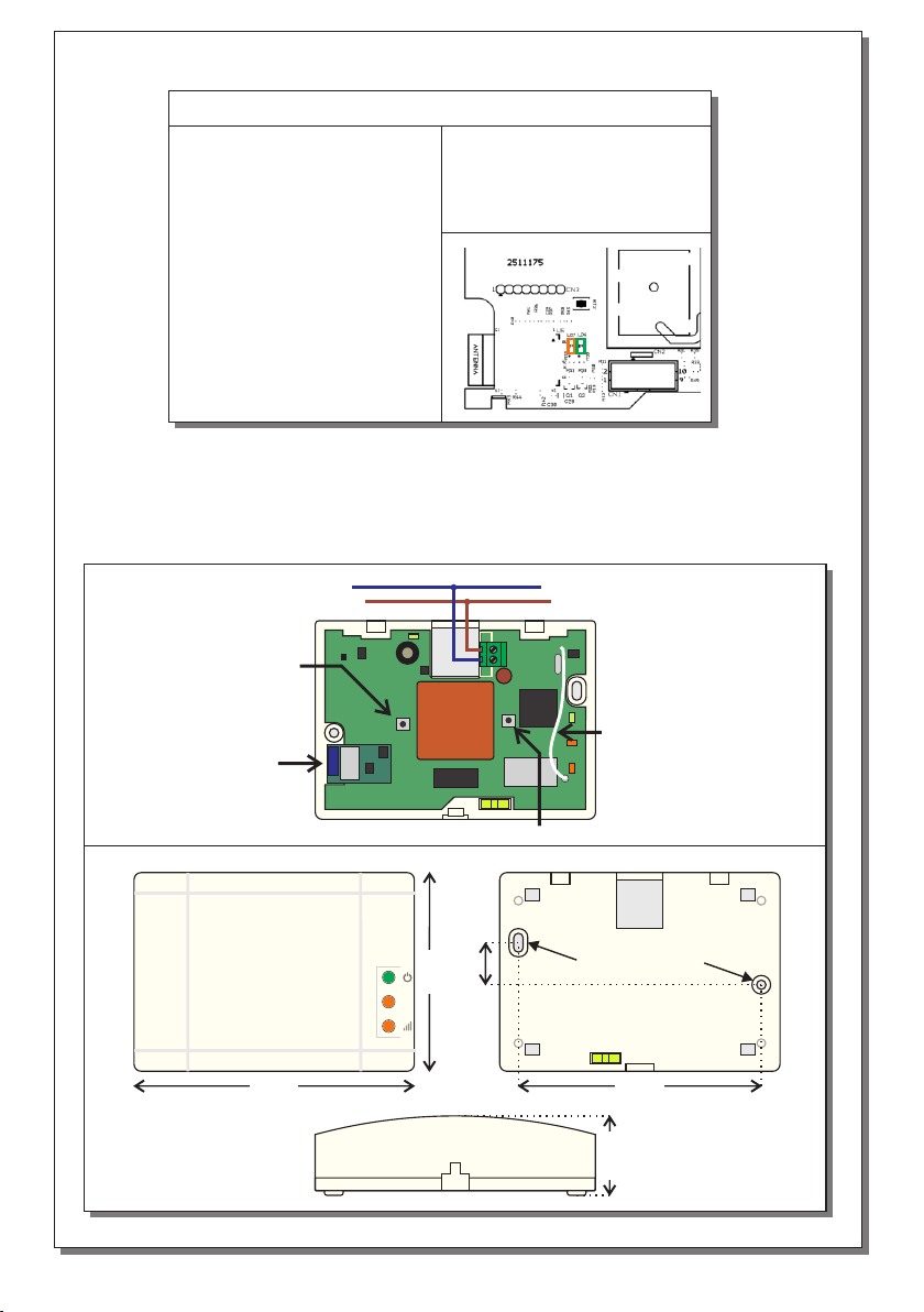
Setup connection via Mini Access Point:
Open the front cover. Press for 2 seconds the button BT2 on the left part of the PCB. The GR-7602
now will establish a temporary mini Wi-Fi Access Point, named as “WL Light WiFi” without security
(Ld7 2 blinks/s) (see page 4 for LED6/7 indications).

923760200_09_001
Page 4 of 5
80mm
19mm
120mm 104mm
RF
34mm
Mounting Holes
L
KL1
BT1
BT2
N
Antenna
Wi-Fi
Transceiver
N
L
Button BT1
Button BT2
LED 6:
• Blinking according to
data traffic (Tx/Rx)
LED 7:
• 1 blink/s - connected to
Wi-Fi network
• 2 blinks/s - mini Wi-Fi AP
established
•3 blinks/s - WPS conn.
activated (N.A.)
• Steady ON - disconnected
from Wi-Fi network
WiFi connection LED Indications:
Schematic 2: Wiring
Schematic 3: Dimensions

Page 5 of 5 923760200_09_001
Loading default settings:
In order to load default settings to the GR-7602 Wifi Gateway, follow the procedure below:
Press BT1 for more than 10s to load default values.
After 20 seconds, the device will establish a Mini AP to setup connection parameters (see
page3).
If you see a message regarding the page being unable to load, try resetting the device with BT1
for 2 seconds.
(Loading defaults does not restore SID and RF Channel values. In order to restore default values on
SID and RF Channel values use the GR-7600 software.)
Default settings:
• Gateway technician menu code (webserver): 1000
• Gateway SID: 00000001
• Gateway channel: 13 (869.525MHz)
• Mini Access Point Gateway IP: 192.168.0.50
WARRANTY
Olympia Electronics guarantees the quality, condition and operation of the goods. The period of warranty
is specified in the official catalogue of Olympia Electronics and also in the technical leaflet, which
accompanies each product. This warranty ceases to exist if the buyer does not follow the technical
instructions included in official documents given by Olympia Electronics or if the buyer modifies the goods
provided or has any repairs or re-setting done by a third party, unless Olympia Electronics has fully
agreed to them in writing. Products that have been damaged can be returned to the premises of our
company for repair or replacement, as long as the warranty period is valid.
Olympia Electronics reserves the right to repair or to replace the returned goods and to or not charge the
buyer depending on the reason of defection. Olympia Electronics reserves the right to charge or not the
buyer the transportation cost.
HEAD OFFICE
72nd km. O.N.R. Thessaloniki-Katerini
P.C. 60300 P.O. Box 06 Εginio Pierias Greece
www.olympia-electronics.gr
Table of contents
Other olympia electronics Gateway manuals
Popular Gateway manuals by other brands

AT&T
AT&T Pace 5168 quick start guide

D-Link
D-Link DPG-2000W - AirPlus G Wireless Presentation... user guide

Cisco
Cisco Linksys WAG54GP2 user guide

TEKTELIC Communications
TEKTELIC Communications Kona Mega Gateway quick start guide

SmartKitchen
SmartKitchen Mobile Gateway 3.0 user manual

Exhausto
Exhausto MB-GATEWAY Technical manual