olympia electronics GR-297/60L/180 User manual

Page 1 from 4923297000 _005_09
SPOT LIGHT EMERGENCY
LUMINAIRE WITH WHITE LEDs
MAINTAINED
OPERATION TEMPERATURE RANGE
RELATIVE HUMIDITY
CONSTRUCTION MATERIAL
EXTERNAL DIAMENTION
WEIGHT
GUARANTEE
OPERATION VOLTAGE
MAXIMUM POWER CONSUMPTION
BATTERY (Ni-MH)
CHARGE TIME
INDICATIONS - CONTROLS
BATTERY PROTECTION
MINIMUM DURATION
DEGREES OF COVER PROTECTION
PRODUCED IN ACCORDANCE WITH
EMERGENCY ILLUMINATION
LIGHT SOURCE
220-240V AC/50-60Hz
3 h sour
24 hours
Discharge and over charge protection
IP40
4.8 1.2V/ Ah
lm 350lm / 110
White LEDs
5.9W / 7.3VA
5 t o 40 C
o
Up to 95%
Bayblend FR3010, clear polycarbonate
3 years (1 year for the battery)
470gr.
Ø125 x 65 mm
EN 60598-1, EN 60598-2-22, ΕΝ 55015, ΕΝ 61547, ΕΝ 61000-3-2, ΕΝ 61000-3-3
Battery charging LED TEST button,
GR-297/60L/180
GENERAL
These luminaires are used indoors ta
where emergency light is needed.
Each lu m i n a i r e m u s t b e p e r m a n e n t l y
connected to mains power supply.
In normal operation the battery is charging and
the illumination source, lights.
In case of a mains power supply failure the
luminaire will light the illumination source
automatically in emergency mode. When the
mains power supply is restored the device
turns to normal operation.
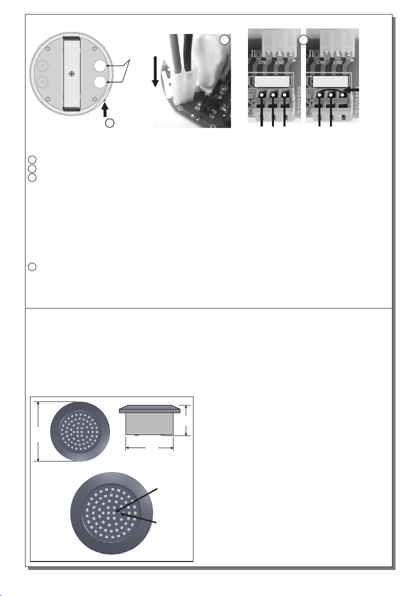
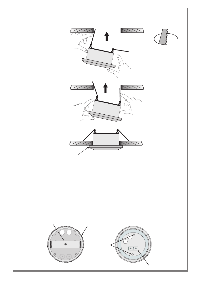
INSTALLATION
To install the luminaire follow the installation
instructions on page 2.
ΑΤΤΕΝΤΙΟΝ!
1. Operations for installation, maintainance or
testing must be done by authorized personel
only.
2. The device must be connected to the mains
power supply thru a fuse dependent by the
total amount of the line’s power load.
3. It is sugested to check every month the
indication LED for battery charging, and by
pushing the TEST button (use a pointy tool
with diameter of 2mm max.) to check the
emergency cirquit. The illumination LEDs
should light as long as the TEST button is
pressed
4. It is sugested to check every 6 months the
m i n i m u m a u t o n o n o u s d u r a t i o n b y
o
(40 C)
!!
. In the opposite condition contact the
installer.
disconnecting the mains power supply Count
the time that the luminaire lights and in case of
less time than the minimum autonomous
duration the battery must be replaced. If the
measured time is considerably less than the
minimum autonomous duration
In case of battery or light source
replacement, these must be replaced by parts
of the same type, by the manufacturer or by a
competent person.
t i
in battery recycling
points. Do not incinerate.
NOTE: LED= Light Emitting Diode
LABELING EXPLANATION:
X: Self contained
1: Maintained (*)
A: Including test device
180: 3 hour duration
(*) Maintained operation: The luminaire lights its
illumination source, when it is powered by the
mains power supply or not.
Non-Maintained operation: The luminaire lights
its illumination source, only in power supply’s
failure.
.
contact the
installer.
5. In case of inactive use for a period greater
than 2 months, disconnect the battery by pulling
out the battery’s connector.
6. I s not allowed to discard batteries in to
common trash bins, they must be
discarded only
TECHNICAL CHARACTERISTICS FOR LED MODULE SPECS (see page 4)
Thank you for your trust in our products.
Olympia Electronics - European manufacturer.

Page 2 from 4923297000 _005_09
Initial installation
1 Untighten the screw but do not remove it and pull up the reflector.
2 Place the battery’s connector to the corresponding connector on the P.C.B.
3 Always use in any case round mains cable, with a diameter of 5-10mm (H05RN-F
type 2x1mm² or any other type, at least equal to it’s mechanical and electrical properties).
ATTENTION!! The cable must not be deformed in any way (This requirement is important
to ensure the ΙΡ rating). Install the included gaskets in to the cable entry holes (verify that are
not deformed). Make a hole in the center by using a small screwdriver. Pass the round cable
through the gasket. Connect the wires Ν for neutral, L for live wire and L1 for the maintained
operation. The L1 wire can be connected to an external switch to control the maintained or non
maintained operation of the luminaire (A). For permanent maintained operation (B) use two wires
to power the luminaire, Ν for neutral and L for live wire, and link the L and L1 as shown in the
picture.
4 Refit the reflector (mind the correct orientation), tighten the screw securely and the luminaire
is ready for mounting.
NOTE!! After finishing the installation you must power the luminaire at least for 24 hours for
battery charging to perform the nοminal autonomy.
INSTALLATION INSTRUCTIONS
2
L1 L1
230V AC230V AC 230V AC
N NL L Link
3
(A) (B)
Battery replacement.
It can be done only by a competent person and after the mains interruption.
1. Remove the luminaire from the suspended ceiling (figure 3).
2. Follow the step 1 of the installation instructions.
3. Disconnect the connector and remove the old battery.
4. Connect the new battery with the same type (step 2 of the installation instructions) and place it in
the position of the old one.
5. Replace the removed parts (step 1 and 4) and power the device.
Figure 1
96
65
125
Test
button
Battery
charge
indication
LED
11
Cable
entry
holes

Page 3 from 4923297000 _005_09
Mounting the luminaire in suspended ceiling.
Set up the luminaire to the suspended ceiling as it is shown bellow (Required opening 110mm)
Step 1
Bend the springs, to get into the hole of the suspended ceiling, as you can see to the next figure.
Step 2
Push up the luminaire, as shown in figure 2.
Step 3
Continue to push upwards until the lamp locks.
:
If you want to pull off the device, put a flat blade
screwdriver, between the device and the ceiling.
Figure 2
Figure 3
Figure 1
Ø110mm
Surface mounting
Install the luminaire according to the following steps
Drill 2 holes on the base using a 4mm drill bit in order to permit the retaining screws to pass.
Mark these two drilled points on the required mounting location, drill the holes and install the
supplied plastic plugs .
Next, use the 2 fasteners to install the unit to
the require location.
.
:
Step 1 .
Step 2. Unfasten the retaining screw (Figure 1) and detach the part for suspended ceiling
installation.
Step 3.
(Figure 2)
Step 4. Install the decorative rim (package included).
Step 5. Follow the steps 2,3 and 4 of the installation instructions.
. Follow the step 1 of the installation instructions
Decorative rim
Drill here
Indications
Retaining fastener
Figure 1 Figure 2

Page 4 from 4923297000 _005_09
LED MODULE CHARACTERISTICS
Manufacturer
Model Number
Voltage Range
Connections
Nominal Power
Temperature (tc)
Olympia Electronics S.A
45 °C max. across the board
Non reversible connection between main pcb and led module
142-176V DC31.9-39.6V DC
0.7W Emergency 3.2W Maintained
0405153
GR-297/60L/180
The light source contained in this luminaire shall only be replaced by the manufacturer, or his
agent, or a similar qualified person.
NOTE! The light source is non-user replaceable.
WARRANTY
Olympia Electronics guarantees the quality, condition and operation of the goods. The period of warranty
is specified in the official catalogue of Olympia Electronics and also in the technical leaflet, which
accompanies each product. This warranty ceases to exist if the buyer does not follow the technical
instructions included in official documents given by Olympia Electronics or if the buyer modifies the goods
provided or has any repairs or re-setting done by a third party, unless Olympia Electronics has fully
agreed to them in writing. Products that have been damaged can be returned to the premises of our
company for repair or replacement, as long as the warranty period is valid.
Olympia Electronics reserves the right to repair or to replace the returned goods and to or not charge the
buyer depending on the reason of defection. Olympia Electronics reserves the right to charge or not the
buyer the transportation cost.
HEAD OFFICE
72nd km. O.N.R. Thessaloniki-Katerini
P.C. 60300 P.O. Box 06 Eginio Pierias Greece
www.olympia-electronics.gr
This manual suits for next models
1
Table of contents
Other olympia electronics Spotlight manuals
Popular Spotlight manuals by other brands

Philips
Philips SmartSpot 57964/48/16 user manual

Knightsbridge
Knightsbridge EMTWINIP Installation & maintenance manual

Eurosep Instruments
Eurosep Instruments IL 2050 quick start guide

ANDlight
ANDlight VOLUMES Series manual

Bohle
Bohle Verifix TwinLED operating instructions

Peak
Peak PKC010WM owner's manual