Page 1 from 5923298002_09_003
GENERAL
These devices are used in places where
emergency luminaires are needed. The
luminaires GR-298/60L/90/WP and GR-
298/30L/180/WP are suitable for open area
lighting. Each device must be permanently
connected to mains power supply. In
normal operation the battery is charging. In
case of a mains power supply failure
the device will light the illumination led
automatically in emergency mode. When
the mains power supply is restored the
device turns to normal operation.
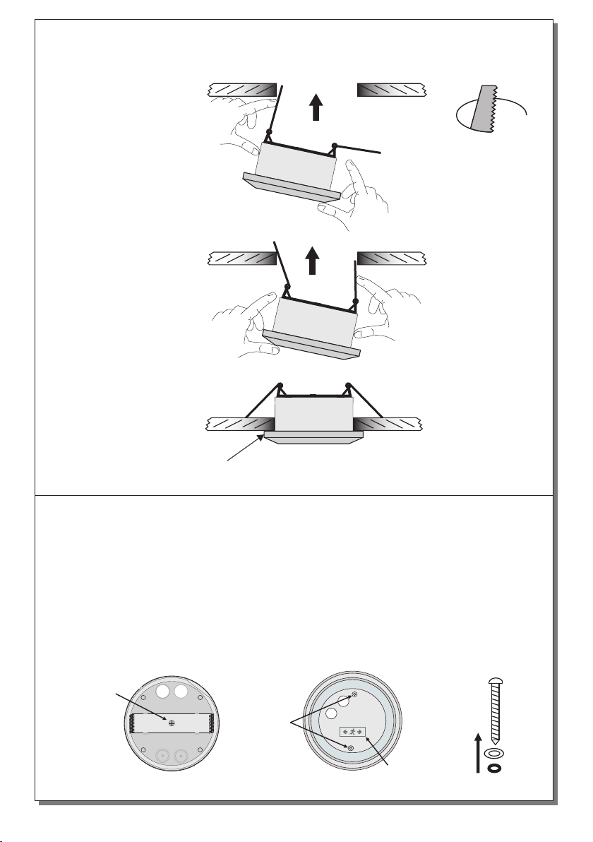
INSTALLATION
To install the luminaire follow the installation
instructions οn page 2.
Battery Charging
The battery charging is completely
controlled. In this case, is achieved the
perfect battery maintenance, as well as the
elongation of its duration. When the battery
has completely charged, it charges with a
maintenance current.
Battery Cut-off
The device enter in this operation when the
mains power supply fails and battery has
lost its energy. During this operation the
device enters the idle state and battery
consumption is negligible, in order to be
protected from deep discharge.
Automatic Operational Test
It is conducted automatically every 15 days.
In order to be performed, the mains power
supply and the battery should be connected.
Automatic Autonomous Test
The Automatic Autonomous Test is
conducted and measures the device’s back
up operation and emergency duration. The
BATTERY FAULT LED blinks during the
measurement, indicating this process to the
user. This test is conducted automatically
every six months. In order to be performed,
the main power supply and the battery
should be connected and fully charged. If
the battery is not fully charged, the test is
postponed until the battery is completely
charged. If during this test, the autonomy is
less than nominal then the battery fault led
turned on continuously and the battery must
be replaced.
SPOT LIGHT WATERPROOF SELF TESTING NON MAINTAINED
EMERGENCY LUMINAIRES WITH WHITE LEDs
TECHNICAL CHARACTERISTICS FOR LED MODULE SPECS (see page 4)
220-240VAC 50-60Hz
3 hours
24 hours
Charge, lamp fault, battery fault, TEST button
Deep discharge and over charge protection
IP 65
4.8V/1.2Ah
60 white LEDs 30 white LEDs
o
5 to 40 C
Up to 95%
ABS/PC, PC
3 years (1 year for the battery)
455 gr.
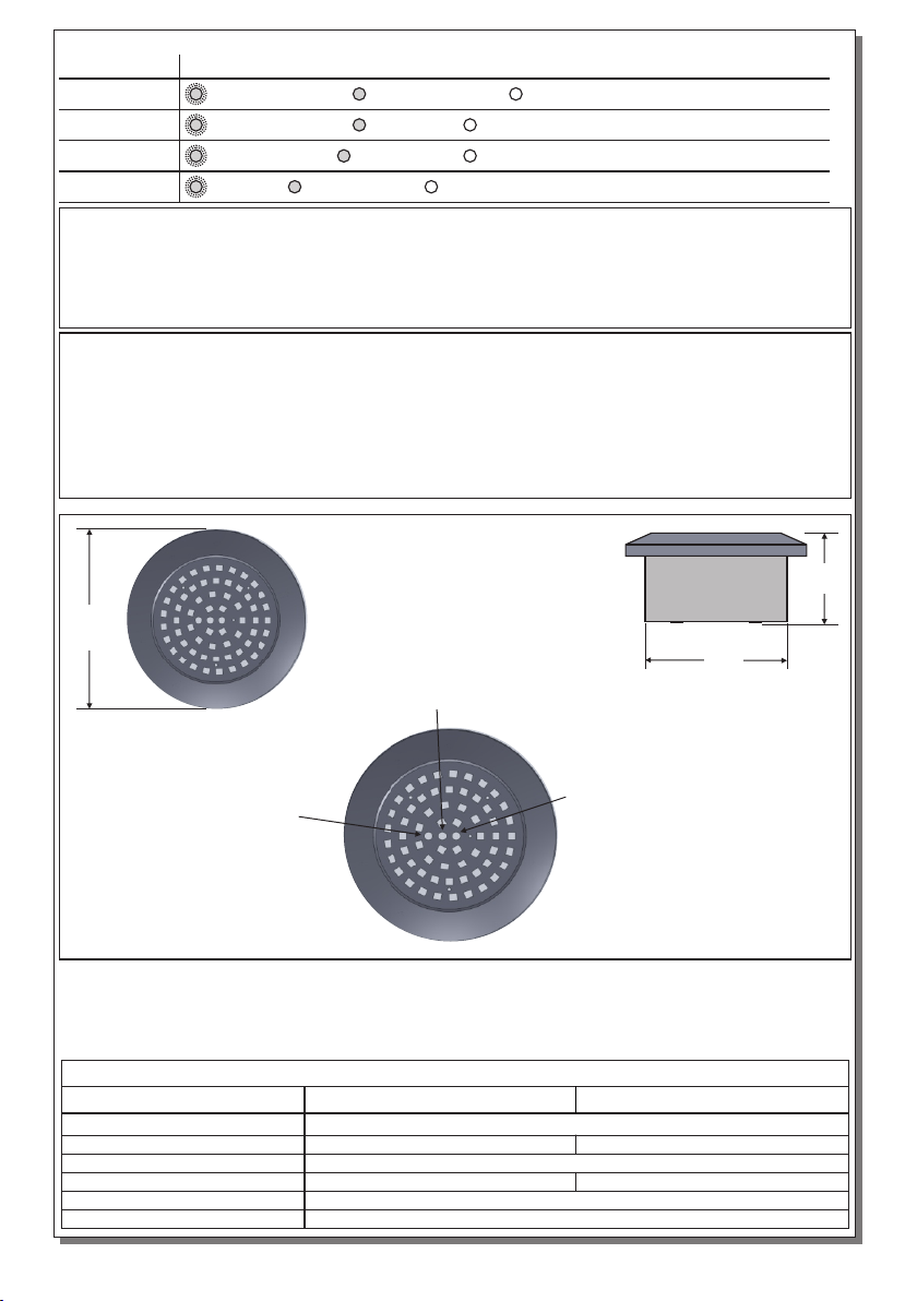
Ø125 x 65 mm
EN 60598-1, EN 60598-2-22, ΕΝ 55015, ΕΝ 61547, ΕΝ 61000-3-2, ΕΝ 61000-3-3
1.5 hour
350lm 170lm
GR-298/60L/90/WP GR-298/30L/180/WP
3.3W / 3.7VA
OPERATION TEMPERATURE RANGE
RELATIVE HUMIDITY
CONSTRUCTION MATERIAL
EXTERNAL DIAMENTION
WEIGHT
GUARANTEE
OPERATION VOLTAGE
MAXIMUM POWER CONSUMPTION
BATTERY (Ni-MH)
CHARGE TIME
INDICATIONS - CONTROLS
BATTERY PROTECTION
MINIMUM DURATION
DEGREES OF COVER PROTECTION
PRODUCED IN ACCORDANCE WITH
EMERGENCY ILLUMINATION
LIGHT SOURCE
Thank you for your trust in our products
Olympia Electronics - European manufacturer