Page 1 from 4
“BAU LIGHT” SERIES SELF TESTING MAINTAINED EMERGENCY LUMINARIES
Page 4 from 4
220-240V AC/50-60Hz
1 h / 3 h / 8 h manually selected (default 3h)
24 h
LED Charge, Battery Fault LED / Magnetic Test Contact
3.6V/3Ah
4.5W / 4.7VA
IP54
EN 60598-1, EN 60598-2-22, ΕΝ 55015, ΕΝ 61547, ΕΝ 61000-3-2, ΕΝ 61000-3-3
o
5 to 40 C
up to 95%
ABS/PC, PC
776gr.
270lm
1 h : 350lm / 3 h : 280lm / 8 h : 90lm
30 white LED
4.1W / 4.3VA
3.6V/1.5Ah
1 h : 300lm / 3 h : 150lm / 8 h : 30lm
745gr. 845gr. 816gr.
OPERATION TEMPERATURE RANGE
RELATIVE HUMIDITY
EXTERNAL DIMENSIONS
CONSTRUCTION MATERIALS
TYPICAL WEIGHT
GUARANTEE
OPERATION VOLTAGE
MAXIMUM POWER CONSUMPTION
BATTERY (Ni-Cd)
CHARGING TIME
INDICATIONS - CONTROLS
MINIMUM AUTONOMY DURATION
DEGREES OF COVER PROTECTION
LUMINOUS FLUX (emergency)
PRODUCED IN ACCORDANCE WITH
LUMINOUS FLUX (230V AC)
VEWING DISTANCE
ILLUMINATION SOURCE
GENERAL
o
These luminaires are used indoors (ta 40 C)
where emergency light is needed.
E a c h l u m i n a i r e m u s t b e p e r m a n e n t l y
connected to mains power supply. In normal
operation the illumination LEDs are lit as well
as the green indicating charge LEDs when the
battery is charging. In case of a mains power
supply failure, the luminaire enters in
emergency mode and will light automatically.
When the mains power supply is restored the
device turns to normal operation.
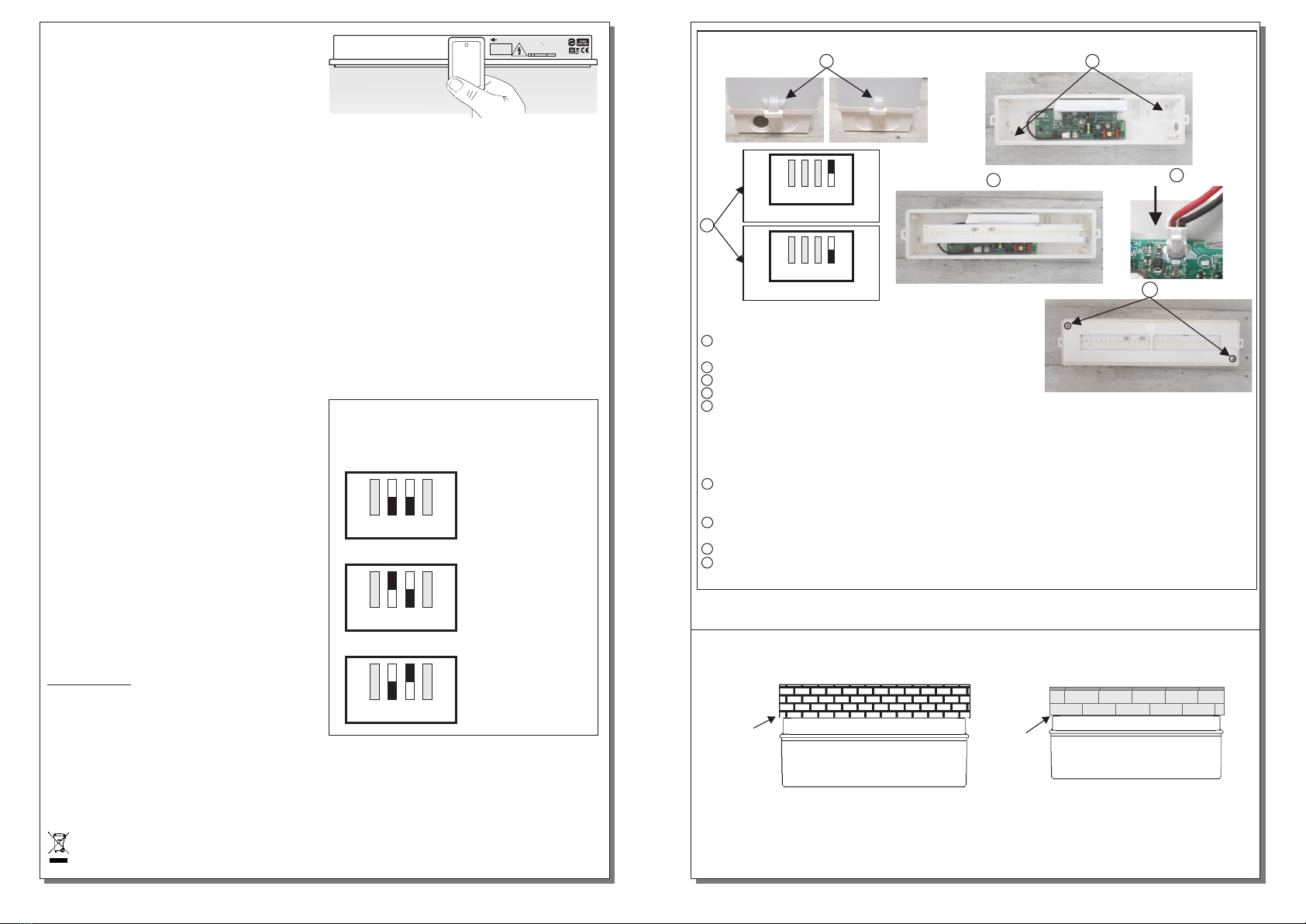
AUTONOMY DURATION SELECTION
The user can select one of the 3 available
minimum autonomy durations 1 hour, 3 hours
and 8 hours. The procedure of autonomy
selection is described on page 2.
TECHNICAL LABEL INSTALLATION
Two additional labels are included in the
package. One for 1 hour duration (60) and one
for 8 hour duration (480). Depending on the
selected duration, the installer must replace the
default 3 hour (180) label with one that has the
required duration. Please take notice of the
orientation of the label.
INSTALLATION
To install the luminaire follow the installation
instructions on page 3.
Battery Charging
The battery charging procedure is controlled by
the processor, this maintaining its best possible
preservation, as it extends its duration.
Battery Cut-off
The luminaire enters this mode when the mains
power supply fails and battery has lost all its
energy. During this operation the luminaire
enters the idle state and battery consumption is
negligible, in order to be protected from deep
discharge.
Manual Test
This test can be done by using the A-1900 card
as described on page 2. The light source and
the emergency circuit of the device are tested.
The manual test can be conducted only if the
mains power supply and the battery are
connected. This test lasts for 3 seconds.
Automatic Operational Test
This test includes all the operations of the
manual test and is conducted automatically
every 15 days. In order to be performed, the
mains power supply and the battery should be
connected. This test lasts for 3 seconds.
Thank you for your trust in our products
Olympia Electronics - European manufacturer
3 years (1 year for the battery)
TECHNICAL CHARACTERISTICS (for LED MODULE specifications see page 4)
Battery replacement.
It can be done only by a competent person and after the mains supply interruption.
1. Dismantle the device (step 1 and step 2 of the installation instructions).
2. Disconnect the connector and remove the old battery.
3. Connect the new battery with the same type (step 6 of the installation instructions) and
place it in the position of the old one.
4. Follow the step 7 of the installation procedure and power the device.
(*) Maintained operation: The luminaire lights its illumination source, when it is powered by
the mains power supply or not.
Non Maintained operation: The luminaire lights its illumination source, only in power supply’s
failure.
NOTE: LED= Light Emitting Diode
LABELING EXPLANATION:
X: Self contained
1: Maintained (*)
A: Including test device
F: Automatic test gear complying
with IEC 61347-2-7 denoted EL-T
G: Internally illuminated
60: 1 hour duration
180: 3 hours duration
480: 8 hours duration
The light source contained in this luminaire shall only be replaced by the manufacturer, or his
agent, or a similar qualified person.
NOTE! The light source is non-user replaceable.
WARRANTY
Olympia Electronics guarantees the quality, condition and operation of the goods. The period of warranty
is specified in the official catalogue of Olympia Electronics and also in the technical leaflet, which
accompanies each product. This warranty ceases to exist if the buyer does not follow the technical
instructions included in official documents given by Olympia Electronics or if the buyer modifies the goods
provided or has any repairs or re-setting done by a third party, unless Olympia Electronics has fully
agreed to them in writing. Products that have been damaged can be returned to the premises of our
company for repair or replacement, as long as the warranty period is valid.
Olympia Electronics reserves the right to repair or to replace the returned goods and to or not charge the
buyer depending on the reason of defection. Olympia Electronics reserves the right to charge or not the
buyer the transportation cost.
HEAD OFFICE
72nd km. O.N.R. Thessaloniki-Katerini
P.C. 60300 P.O. Box 06 Εginio Pierias Greece
www.olympia-electronics.gr
LED MODULE CHARACTERISTICS
Manufacturer
Model Number
Voltage Range
Connections
Nominal Power
Temperature (tc)
Olympia Electronics S.A
45 °C max. across the board
Non-reversible connection between main pcb and led module
13-14VDC13-13.6VDC
2W max1.5W max
2505195
GR-750/ST/HP/LL GR-751/ST/LP/LL GR-752/ST/HP/HL GR-753/ST/LP/HL
X1AF18 0
G
358 x 85 x 88 mm358 x 125 x 88 mm 358 x 85 x 88 mm 358 x 125 x 88 mm
*15m, **17m 15m 15m
*15m, **17m
NOTE!! The installer should fill in, on the specification
label, the letter G if the luminaire is used as a safety sign.
GR-750/ST/HP/LL GR-751/ST/LP/LL GR-752/ST/HP/HL GR-753/ST/LP/HL
923753000_09_004923753000_09_004