manuals.online logo
Brands
  1. Home
  2. •
  3. Brands
  4. •
  5. Olympus
  6. •
  7. Adapter
  8. •
  9. Olympus U-TV1XC User manual

Olympus U-TV1XC User manual

A X 7 9 0 1 U-TV1XC
C-MOUNT CAMERA ADAPTER
U-TV1XC INSTRUCTIONS
This instruction manual is for the Olympus C-Mount Camera Adapter model U-TV1XC, which allows a digital camera
or TV camera to record microscopic images (1X) directly from a microscope.
Before disposing of this product, be sure to follow the regulations and rules of your local government.
2 Assembly
3 Operation
1 System Chart
Fig. 1
Attaching on a UIS Trinocular Tube (Fig. 1)
1. Screw the camera adapter @ securely into the C-mount camera 2.
2. Using the Allen screwdriver provided with the microscope, loosen the
clamping screw 3on the UIS2 (UIS) trinocular tube and insert the mount
dovetail | of the camera adapter into the camera adapter mount 5 of
the trinocular tube.
3. Tighten the clamping screw 3firmly.
Adjusting the Microscope
1. Ignite the microscope light source and adjust the microscope modules
to make the microscope ready for observation.
2. Select the camera light path of the trinocular tube.
Adjusting the Camera and Monitor
Perform adjustments such as the color adjustments by referring to the
instruction manuals for the camera and monitor.
}The center of the eyepiece image may not come on the center of
the monitor screen. This phenomenon is due to the mechanism for
adjustment of the camera’s image sensor and not malfunction.
C-Mount Camera Adapter
U-TV1XC
· UIS2 (UIS)
trinocular tube*
· SZX2
· U-TRU
· U-TRUS
· C-mount microscopic digital camera**
· C-mount TV camera**
(With 1-inch or smaller image sensor)
*A UIS2 (UIS) trinocular observation tube (U-TTR-2, U-TR30-2, U-TR30NIR, U-SWTR-3, etc.) can be used. The MVX10
cannot be combined with this product.
** Camera restrictions
· A camera may be unusable if its C-mount plane is lower than the camera body surface.
· If the camera uses an image sensor larger than specified, the image periphery may become dark or obscured.
1
2
5
43
Fig. 3
Adjusting the Parfocality of the Observation Image and Monitor
Image (Fig. 2)
}The parfocality adjustment makes it unnecessary to correct focusing when
the observation image is switched to the monitor image.
Use the Allen screwdriver provided with the microscope for this adjust-
ment.
The parfocality adjustment range is ±1.5 mm. If the adjustment
on this adapter is not enough, please also use the focusing
function of the camera.
1. Using a high-power objective, look into the eyepieces and bring the
specimen in focus.
2. Switch to a low-power objective, select the camera light path and observe
the monitor image.
3. Loosen the clamping screw @ of the trinocular tube and the clamping
screw 2of the camera adapter. Then, while observing the monitor image,
hold the top 3of the camera adapter and turn its bottom | to adjust
the focus.
}The fixing screw of the camera adapter may not necessarily be located on
the front side. If you cannot find the fixing screw of the camera adapter on
the front side, please check either sides or the back side of the camera
adapter.
4. When the monitor image is focused, tighten the clamping screws @ 2
firmly.
Adjusting the Centering of the Camera Adapter (Fig. 3)
}The centering adjustment makes it possible to reduce the deviation of
image between two objectives.
1. Using the Allen screwdriver, loosen the screw marked “LOCK” @ until it
is projected by 3 or 4 mm from the camera adapter surface.
}Do not loosen the screw too much. Otherwise, it may slip out of the camera
adapter.
2. Engage the objective with higher power in the light path and move the
stage to bring the target region of the specimen on the center of the
monitor image.
3. Engage the objective with lower power in the light path and perform the
following operation to bring the target region on the center of the monitor
image.
(Turn each of the two screws marked “CENTERING” 2using the Allen
screwdriver so that the target region is brought on the center.)
}To improve the centering accuracy, repeat steps 2 and 3 as required.
4. Tighten the screw marked “LOCK” @ firmly.
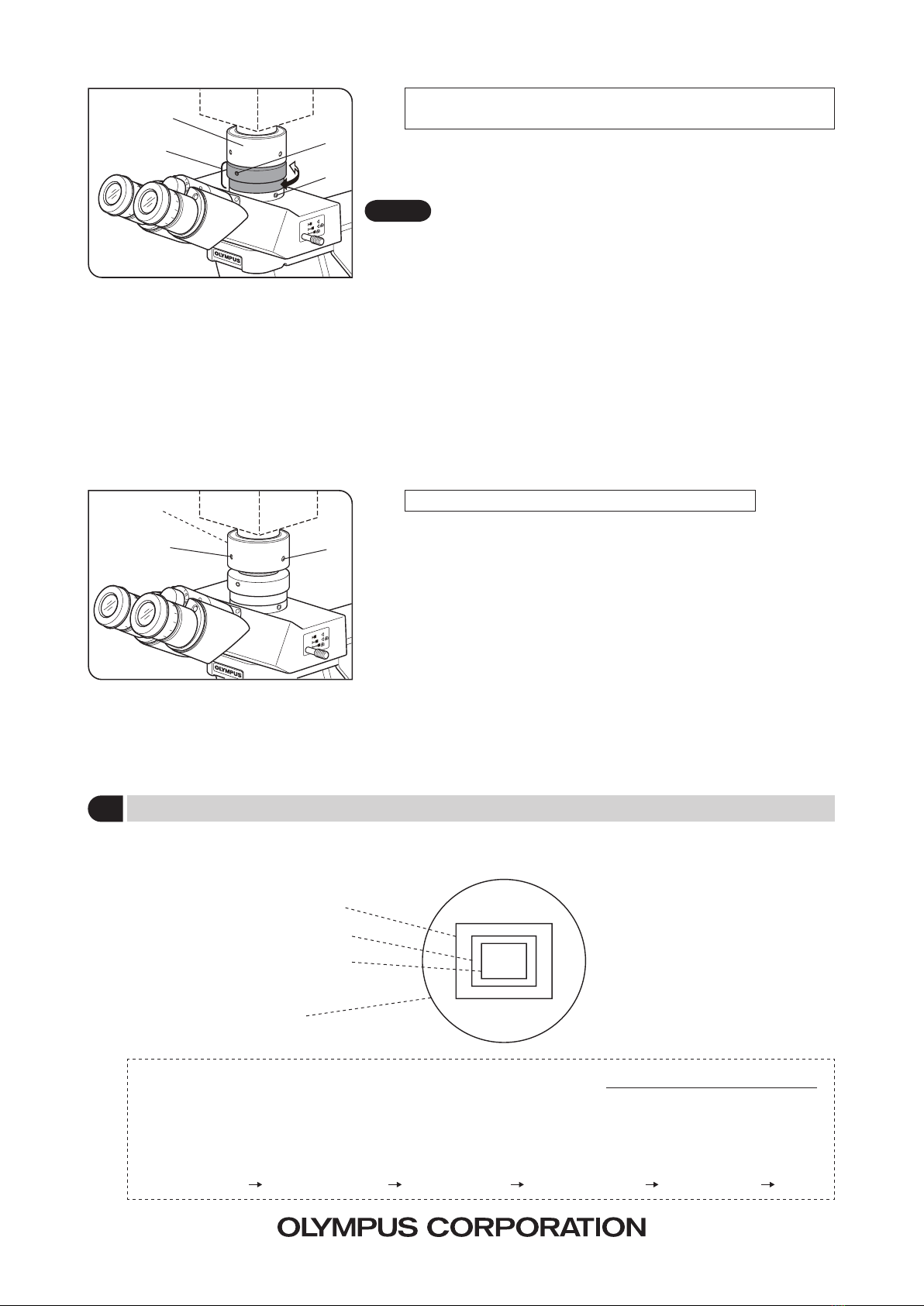
4 Image Pickup Areas
}The following illustration shows field of view of eyepieces with a FN of 22 and the image pickup areas of the camera
adapter depending on the image sensor size.
1-inch image sensor
2/3-inch image sensor
1/2-inch image sensor
FN 22
Magnification on
the monitor
M-02
2
2
Diagonal size of monitor screen*
Diagonal size of image sensor*
*Note that the actual diagonal lengths of the monitor and image sensor may vary slightly depending on
manufacturers.
(Reference data for image sensor sizes)
1-inch camera 16.16 mm. 2/3-inch 11 mm. 1/2-inch 8.08 mm. 1/3-inch 6 mm. 1/4-inch 4 mm.
=Objective power ×Camera adapter
power (1X) ×
CAUTION
Fig. 2
1
2
4
3
1

Other Olympus Adapter manuals

Olympus MAPC-10 User manual

Olympus

Olympus MAPC-10 User manual

Olympus U-TV0.63XC User manual

Olympus

Olympus U-TV0.63XC User manual

Olympus U-TV0.63XB User manual

Olympus

Olympus U-TV0.63XB User manual

Olympus CAMEDIA MAFP-1E User manual

Olympus

Olympus CAMEDIA MAFP-1E User manual

Olympus F-2AC User manual

Olympus

Olympus F-2AC User manual

Olympus MMF-1 User manual

Olympus

Olympus MMF-1 User manual

Olympus IPLEX TX User manual

Olympus

Olympus IPLEX TX User manual

Olympus F-5AC-2 User manual

Olympus

Olympus F-5AC-2 User manual

Olympus xD-Picture Card MAUSB-200 Guide

Olympus

Olympus xD-Picture Card MAUSB-200 Guide

Olympus AC-2 User manual

Olympus

Olympus AC-2 User manual

Olympus U-TV0.35XC-2 User manual

Olympus

Olympus U-TV0.35XC-2 User manual

Olympus xD-Picture Card MAUSB-300 Guide

Olympus

Olympus xD-Picture Card MAUSB-300 Guide

Olympus MACF-10 User manual

Olympus

Olympus MACF-10 User manual

Olympus MAPC-10 User manual

Olympus

Olympus MAPC-10 User manual

Olympus MAUSB-500 User manual

Olympus

Olympus MAUSB-500 User manual

Olympus U-DPCAD User manual

Olympus

Olympus U-DPCAD User manual

Olympus E-System MF-2 User manual

Olympus

Olympus E-System MF-2 User manual

Popular Adapter manuals by other brands

Discount Car Stereo AUX-CR12 installation guide

Discount Car Stereo

Discount Car Stereo AUX-CR12 installation guide

Rational iVario Original installation manual

Rational

Rational iVario Original installation manual

Altronix Pace1KRT installation guide

Altronix

Altronix Pace1KRT installation guide

ACN HT802 Quick installation guide

ACN

ACN HT802 Quick installation guide

ABB NIBA-01 Installation and startup guide

ABB

ABB NIBA-01 Installation and startup guide

Addonics Technologies ADU3ESA user guide

Addonics Technologies

Addonics Technologies ADU3ESA user guide

1More DH3001B user guide

1More

1More DH3001B user guide

Ovislink AirLive EtherWe-1000U user manual

Ovislink

Ovislink AirLive EtherWe-1000U user manual

Pace DC60Xu quick start guide

Pace

Pace DC60Xu quick start guide

Sony ACV-700 operating instructions

Sony

Sony ACV-700 operating instructions

R&S ZZA-GE23 Assembly instruction

R&S

R&S ZZA-GE23 Assembly instruction

TiGHT AV AU-X2I-DA user manual

TiGHT AV

TiGHT AV AU-X2I-DA user manual

Philips SWA4552W Specifications

Philips

Philips SWA4552W Specifications

Konig P.SUP.NBT125K1 manual

Konig

Konig P.SUP.NBT125K1 manual

Ovislink PL-DUO210/85 user guide

Ovislink

Ovislink PL-DUO210/85 user guide

Shuttle H-RS232 Quick installation guide

Shuttle

Shuttle H-RS232 Quick installation guide

Edimax EW-7608Pg Specifications

Edimax

Edimax EW-7608Pg Specifications

TP-Link TL-PA4010 Quick installation guide

TP-Link

TP-Link TL-PA4010 Quick installation guide

manuals.online logo
manuals.online logoBrands
  • About & Mission
  • Contact us
  • Privacy Policy
  • Terms and Conditions

Copyright 2025 Manuals.Online. All Rights Reserved.