OmarLift HEVOS HE650 User manual

D878 MGB Rev00 HE650.docx 1/50
OPERATING INSTRUCTIONS FOR
HEVOS HE650 VALVE

2/50 D878 MGB Rev00 HE650.docx

D878 MGB Rev00 HE650.docx 3/50
General Index
0General information ................................................................................................................................... 5
1General Infon............................................................................................................................................. 6
1.1 Warning on how to operate................................................................................................................ 6
1.2 Inspection on delivery........................................................................................................................ 6
1.3 Storage .............................................................................................................................................. 6
1.4 Disposing........................................................................................................................................... 6
1.5 Directives and technical standards considered ................................................................................. 6
2Schemes and adjustments ........................................................................................................................ 7
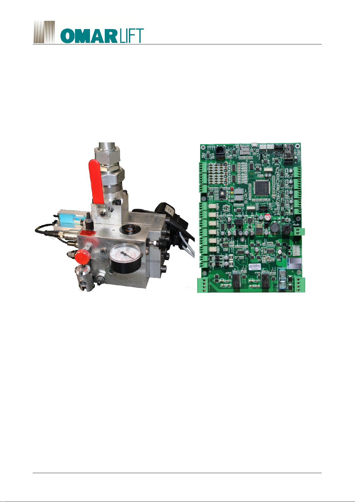
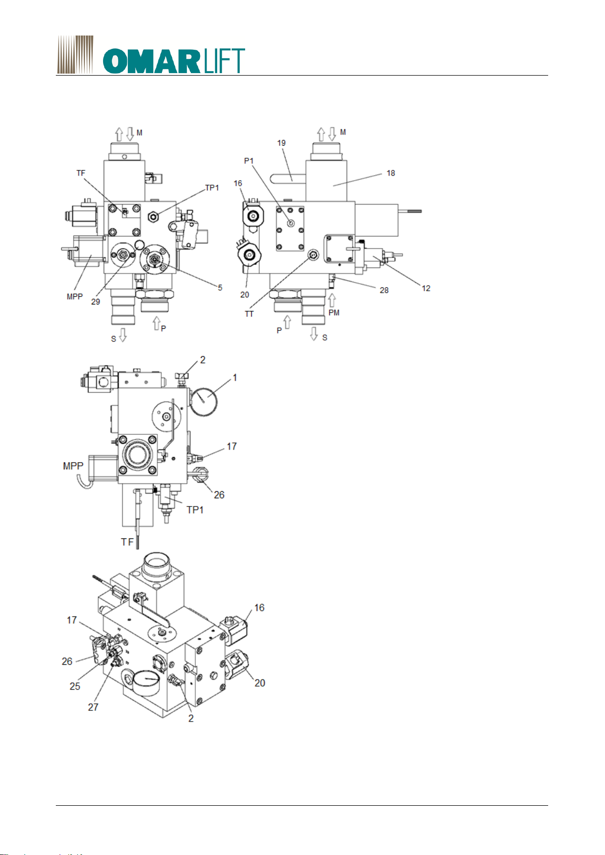
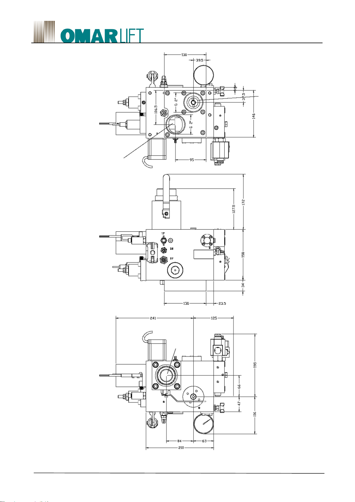
2.1 Main components .............................................................................................................................. 7
2.2 Hydraulic diagram.............................................................................................................................. 8
2.3 Valves functionaldiagram................................................................................................................... 9
2.4 Main components and connections of SCH001 board.................................................................... 11
2.5 Posizioni commutatore RSW........................................................................................................... 12
2.6 Wi-fi connection (Optional) .............................................................................................................. 12
2.7 SD-CARD parameters and records recovery.................................................................................. 12
2.8 SD-CARD parameters loading......................................................................................................... 13
2.9 Overload pressure automatic setting............................................................................................... 13
2.10 Software updating procedure........................................................................................................... 13
2.11 Working cycles parameters ............................................................................................................. 14
2.12 Signal and speed parameters combination..................................................................................... 15
2.13 Command device working diagram ................................................................................................. 16
2.14 SCH100 board dimensions and fixing ............................................................................................. 17
2.15 Upward working cycle...................................................................................................................... 18
2.16 Downward working cycle................................................................................................................. 20
2.17 Releveling........................................................................................................................................ 21
2.18 Rapture valve test (DSP=FC, FP) ................................................................................................... 21
2.19 Maximum pressure valve test (DSP=PP, HP)................................................................................. 22
2.20 Error condition ................................................................................................................................. 22
2.21 Upward working cycle diagram........................................................................................................ 23
3Protection against the uncontrolled movement of the cabin (UCM)........................................................ 24
3.1 Introduction...................................................................................................................................... 24
3.2 Schedule of operation signals and controls..................................................................................... 24
3.3 Test device against uncontrolled movement (DSP=uc, up ) ........................................................... 25
3.3.1 Ascent with empty car, and positioned in the upper part of the compartment ........................ 25
3.3.2 Descent with a full load in the cabin, and the cabin located at the bottom of the compartment
25
3.4 Self-control of type of functional redundancy .................................................................................. 25
3.4.1 Cycle with self monitoring functional redundancy.................................................................... 26
3.5 Verification of the periodic self-monitoring function of redundancy................................................. 27
3.5.1 Check the VSC valve sealing .................................................................................................. 27
3.5.2Check the VNR valve sealing.................................................................................................. 27
3.6 Self-control of monitoring PNP1 signal............................................................................................ 27
3.7 Control of the cycle of monitoring PNP1 signal............................................................................... 28

4/50 D878 MGB Rev00 HE650.docx
3.8 Verification of the supervisory function of monitoring PNP1 signal................................................. 28
3.8.1 Always check ON signal.......................................................................................................... 28
3.8.2 Always check signal OFF ........................................................................................................ 29
3.8.3 Verification normal operation................................................................................................... 29
3.9 Identification and traceability ........................................................................................................... 29
4Manoeuvres of emergency valve unit HEVOS HE650............................................................................ 30
4.1 Downward movement of the cabin .................................................................................................. 30
4.2 Upward movement of the cab.......................................................................................................... 30
5Parameters errors and codes HEVOS HE650 valve unit........................................................................ 31
5.1 Parameters ...................................................................................................................................... 31
5.2 Errors............................................................................................................................................... 36
6Automatic reduction of travel times ......................................................................................................... 39
6.1 Recovery leveling space.................................................................................................................. 39
6.2 Reduction of starting time and maximum upward speed ................................................................ 39
6.3 With VVVF drive working valve unit HEVOS HE650....................................................................... 40
7Maintenance valve unit HEVOS HE650.................................................................................................. 41
7.1 Maintenance program and periodic checks..................................................................................... 41
7.2 Description of controls ..................................................................................................................... 41
7.3 Filters and solenoid valve................................................................................................................ 42
8Schemes and adjustments multi-valve.................................................................................................... 44
8.1 Description....................................................................................................................................... 44
8.2 Hydraulic scheme............................................................................................................................ 45
8.3 Connections master - slave............................................................................................................. 46
8.4 Diagram of functioning control devices............................................................................................ 47
9EU-type certificate (example) .................................................................................................................. 48

D878 MGB Rev00 HE650.docx 5/50
0 General information
This manual is integrant part of the unit therefore must be kept for the lasting in operation of the unit, in a place
accessible and known by the installation, use and maintenance personnel.
The herewith instructions aim to permit the positive and safe execution of the installation operations, starting-
up, working, control, maintenance and possible repair of the unit.
If any situation or event, not specified in the following pages, should occur, please refer to OMARLIFT
Technical Assistance and always specifying the identification data shown on the product.

6/50 D878 MGB Rev00 HE650.docx
1 General Infon
The HE650 Valve unit is a component designed for use in lifting systems such as elevators and goods lifts.
The function of the valve assembly, is to control the speed of the cabin and is to represent the stop element,
downward.
It is forbidden the commissioning of the valve unit as part of a lifting system that has not been declared in
conformity with local regulations.
The room where the unit is instalLED must be ventilated, free from dust and moisture.
1.1 Warning on how to operate
All the safety measures in force have to be observed carefully to prevent competent staff or any possible non
competent persons or objects, from damages or accidents.
These operating instructions report some symbols, which correspond to important safety measures:
This symbol warns that not observing the related instruction involves a risk of damage to the unit or to
the system
This symbol warns that not observing the related instruction involves an electric shock risk.
1.2 Inspection on delivery
On delivery, check that the material has not been damaged during transportation from the production plant;
check that the packing is undamaged and that you have all the necessary accessories and / or required; also
check the correspondence of data on delivery and identification plates with those of the expected material.
1.3 Storage
In the installation waiting, the group must be stored away from the elements (can be especially damaged by
water, damp and sun) and in a stable position. The temperature of the storage location should be between 0
and + 50 ° C (32 and 122 °F)
1.4 Disposing
The device must be disposed of according to applicable regulations.
1.5 Directives and technical standards considered
Standard - Directive
Title
2014/33/UE
Lift Directive
EN 81-20:2014
Safety rules for the construction and installation of lifts
EN 81-50:2014
Design rules, calculations, examinations and tests (Elevator)
2006/42/CE
Machinery Directive
2014/35/UE
Low voltage Directive
2014/30/UE
Electromagnetic compatibility Directive
EN 12015:2014
Electromagnetic compatibility - Emission
EN 12016:2016
Electromagnetic compatibility - Immunity
EN 60068-2-6
Vibration
Environmental testing - Part 2: Tests - Test Fc: Vibration
EN 60068-2-14
Temperature
Environmental testing - Part 14: Tests - Test N. Change of
temperature
EN 60068-2-27
Shock
Environmental testing - Part 2-27: Tests - Test Еа and guidance:
Shock
EN 60664-1: 2007
Insulation coordination for equipment within low-voltage
systems
2011/65/EU
RoHS 2 Directive - on the restriction of the use of certain
hazardous substances in electrical and electronic equipment

D878 MGB Rev00 HE650.docx 7/50
2 Schemes and adjustments
2.1 Main components
MAIN COMPONENTS
1 Gauge
2 Gauge cut-out cock
5 Maximum pressure valve adjusting screw
- clockwise increase (+) - anticlockwise decrease (-)
12 VSC valve zero contact
16 ENR solenoid valve (unblock VNR valve)
17 Emergency manual lowering (clockwise rotation)
18 Filter
19 Ball valve
20 ERS solenoid valve (unblock VSR valve)
25 Emergency manual lowering minimum pressure
- clockwise increase (+) - anticlockwise decrease (-)
26 Hand pump
27 Hand pump maximum pressure valve
- clockwise increase (+) - anticlockwise decrease (-)
28 Hand pump non-return valve
29 Hand pump air-release screw
TF Flow meter
TP1 Pressure meter
TT Temperature meter
MPP VSC valve command Stepper motor
M Cylinder port
P Pump port
S Tank port
PM Hand pump input port
(P1) Auxiliary micro-relevelling port
OPERATING LIMITS METRIC USA
- Max static pressure: 45 bar 650 psi
- Max operating pressure: 55 bar 800 psi
- Minimum pressure: 10 bar 145 psi
- Flow: 250 - 700 l/min 65 - 185 gpm
- Room temperature: 10 - 60 °C 50 - 150 °F
- Viscosity: 14 - 290 cSt

8/50 D878 MGB Rev00 HE650.docx
2.2 Hydraulic diagram
LEGEND
1 Gauge
2 Gauge cut-out cock
5 Maximum pressure valve adjusting screw
- clockwise increase (+) - anticlockwise decrease (-)
12 VSC valve zero contact
16 ENR solenoid valve (unblock VNR valve)
17 Emergency manual lowering (clockwise rotation)
18 Filter
19 Ball valve
20 ERS solenoid valve (unblock VSR valve)
23 VSC valve block control throttle
25 Emergency manual lowering minimum pressure
- clockwise increase (+) - anticlockwise decrease (-)
26 Hand pump
27 Hand pump maximum pressure valve
- clockwise increase (+) - anticlockwise decrease (-)
28 Hand pump non-return valve
29 Hand pump air-release screw
97 VNR valve block control throttle
TF Flow meter
TP1 Pressure meter
TT Temperature meter
ENR VNR valve unblock solenoid valve
ERS VSC valve unblock solenoid valve
MPP VSC valve command Stepper motor
VNP Pump no return valve
VNR No return and downstroke safety valve
VPM Pump maximum pressure valve
VSC Flow control valve
P1 Auxiliary microrelevelling port
OTHER PUMP UNIT COMPONENTS
M Pump motor
P Pump
S Pump silencer
T Flexible pump connection pipe

D878 MGB Rev00 HE650.docx 9/50
2.3 Valves functional diagram
LEGEND
1 Gauge
2 Gauge cut-out cock
5 Maximum pressure valve adjusting screw
- clockwise increase (+) - anticlockwise decrease (-)
12 VSC valve zero contact
16 ENR solenoid valve (unblock VNR valve)
17 Emergency manual lowering (clockwise rotation)
18 Filter
19 Ball valve
20 ERS solenoid valve (unblock VSR valve)
23 VSC valve block control throttle
25 Emergency manual lowering minimum pressure
- clockwise increase (+) - anticlockwise decrease (-)
26 Hand pump
27 Hand pump maximum pressure valve
- clockwise increase (+) - anticlockwise decrease (-)
28 Hand pump non-return valve
29 Hand pump air-release screw
97 VNR valve block control throttle
TF Flow meter
TP1 Pressure meter
TT Temperature meter
ENR VNR valve unblock solenoid valve
ERS VSC valve unblock solenoid valve
MPP VSC valve command Stepper motor
VNP Pump no return valve
VNR No return and down stroke safety valve
VPM Pump maximum pressure valve
VSC Flow control valve
P1 Auxiliary micro-relevelling port
(M) Cylinder port
(P) Pump port
(S) Tank port
(PM) Hand pump input port
(SM) Maximum pressure valves draining
OTHER PUMP UNIT COMPONENTS
M Pump motor
P Pump
S Pump silencer
T Flexible pump connection pipe

10/50 D878 MGB Rev00 HE650.docx
Pipe
axis
piston
Weight:21kg
Measures in mm
Pump connection shaft
Tank unloading axis

D878 MGB Rev00 HE650.docx 11/50
2.4 Main components and connections of SCH001 board
ATTENTION: Reversing the polarity on the 24VDC supply, or inversion f m2 and M3 connectors, will
irreparably damage the board!
SUPPLY
M1 Input Voltage board 24-30 VDC
- Max input power 25 W 25 W
- Standby consumption 24VDC:
200mA,300mA with conencted data entry device
F1 Fuse5A-T
M2 Solenoid valve ENR 24-30 VDC 35 W input
Solenoid valve ERS 24-30 VDC 35 W input
SWITCHING RELAY OUTPUT 2A-220VDC / 0.25A-250VAC
CN9 AVV Motor Pump starting
CN10 T1 TMAX-TMIN (Par.105-110) temperature range exit:
> Par.105 always active,
< Par. 110 during waiting command only active
CN11 P1 PMAX-PMIN pressure rangeexit, (Par.106-107)
always active if Par.457 =1 otherwise
during waiting command only active if Par. 457=0
CN12 P2 Overload PS pressure limit overcoming, (Par.108)
during waiting command only active
CN13 ERR Stato Error condition
CN14 RDY Ready condition
LD29 LED Red ON = Error condition
LD30 LED Yellow ON= CAN operating
LD31 LED Green ON = Normal condition
LD32 LED Blue ON = Wi-Fi module activated
LD35 LED Orange. ON = SD memory activated
OPTO-ISOLATED DIGITAL INPUT
- Working voltage 20 - 60 VDC - 100 mA
CN6 UP Upward command input
DW Downward command input
HSP Upward high speed command input
(Downward also when Par. 453 = 0)
MSP Upward high speed command input
(Downward also when Par. 453 = 0)
CN7 SFY Motor Pump ON signal
SP1 V3 Speed (together high speed command input)
SP2 V4 Speed (together high speed command input)
SP3 Downward high speed command input
(when Par. 453 = 1)
CN8 -V Digital input negative common
0V Bridge with -V negative for dry contacts
+24V Voltage for dry contacts utilization max 100 mA
VOLTAGE DIGITAL OUTPUT - V = 23 VDC - 500mA - PNP type
CN15 PNP1 Valve monitoring signal
CN16 PNP2 Not used
M3 ENRsolenoidvalveconnection
ERS solenoid valve connection
RSW Working selector with 10 position
S1-S2 Confirmation keys
RJ11 Hand terminal connection
SD Micro SD 2-16 GB FAT32
CN20 Stepper motor connection
USB Micro-Usb PC direct connection
CAN CAN net connection
Wi-Fi Wi-Fi net connection module
ZERO VSC(CN5) TF(CN4), TP1(CN2), TT(CN1), sensor input
DSP1-2 Digit signalyng display

12/50 D878 MGB Rev00 HE650.docx
2.5 Posizioni commutatore RSW
With the selector in a position other than 0, the Ready signal (Pos.CN14) is normally deactivated and
reactivated momentarily during the execution of a specific command.
The Red LED near the RSW selector shows the position of the selector itself:
The always-on LED corresponds to the position 0, while it executes a flash sequence corresponding to the
number of other selected positions.
(*) Sensor pressure value and automatic setting of overload pressure display
(**) The DSP1-2 display turns off after 10 s in the absence maneuvers
(***) Switching the RSW selector in 0 position and pressing the S1 button the command is deleted
2.6 Wi-fi connection (Optional)
To use a Wi-Fi device for managing parameters, it is necessary to install on your Smartphone a
dedicated application named Hevos OMARLIFT, which is available on Google Play Store and Apple
Store.
-Switches the RSW selector in the position 2, the display will then indicate [UF]
-Wait until the LD32 blu LED is fixed ON
-Search your device and connect the Wi-Fi whose name corresponds to the network identifier indicated
in the 499 parameter the name of serial number (ex. 16187901)
-Start the application and when the login key is required, enter the name of Wi-Fi network (ex.
16187901).
With the RSW selector in the position number 2 you can change the parameters, otherwise with the RSW
selector in others position, you can only view the parameters.
If the RSW selector is not in the position number 2, the LD32 blue light and the WIFi network fall when there
is no connection for more that one minute.
However, remember to return to the position 0 of the switch RSW.
2.7 SD-CARD parameters and records recovery
To save the parameters via SD CARD must use a Micro SD 2 to 16 GB already formatted FAT 32.
-Switch the RSW selector in position 7, the display will then show [oc] and will turn on (ON) Yellow
LED LD35.
Records Recovery (200302 softwar version and higher)
-Then press S1 button, the display will then show [Su] after performing an upstroke or [Sd] after
performing a downstroke, once and the Yellow LED will start flashing (ON-OFF) until the completion
of the writing of the records on the SD card.
If present in memory, both the upstroke and downstroke recording will be saved.
Parameters Recovery
-Then press S2 button, the display will then show [SP] once and the Yellow LED will start flashing (ON-
OFF) until the completion of the writing of the parameters on the SD card.
Both the saving of the recordings and that of the parameters, resets the SCH001 card, with indication [--] on
the display, which will therefore lose the recordings of upstroke and downstroke into memory.
The file containing the parameters on the SD card is named with the number corresponding to network ID,
stored in the 499 parameter, with PAR extension (ex. 16187901.PAR) for the parameters, and UPR and DWR
extensions for the upstroke and downstroke records, with the 31/12/2097 generic creation date.
Then the display will show [00] and the Yellow LED will turn off (OFF) and the Green LED executes a blinking
(ON-OFF-ON).
After the display shows [oc] and will turn on again (ON) LED Yellow.
However, remember to return to the position 0 of the switch RSW.
RSW SELECTOR POSITION
DSP1-2
CONFIRMATION
BUTTON
DSP1-2
0 NORMALWORKINGCONDITION
(00) (**)
/
1 HANDTERMINALPARAMETERMODIFICATION
(*)
/
2 WI-FI NETPARAMETER MODIFICATION(**)
(uf)
/
3 DROP TEST CONDITION
(FC)
S1
(fp) (***)
4 UCMTEST
(uc)
S1
(UP) (***)
5 SD-CARDPARAMETERSREADING
(Ic)
S2
6 PNP1 SIGNALTEST
(c-)
S1/S2
(Cu)(cd) (***)
7 SD-CARDPARAMETERSANDRECORD WRITING
(oc)
S2/S2
8 MAXIMUMPRESSUREVALVETESTCONDITION
(PP)
S1
(HP) (***)
9 LASTERRORNUMBERDISPLAY
(--)
S1=RESET

D878 MGB Rev00 HE650.docx 13/50
2.8 SD-CARD parameters loading
To read the parameters from SD CARD must use a Micro SD 2 to 16 GB, formatted FAT 32.
The card must contains the file with the number corresponding to network ID stored in the 499 parameter and
PAR extension (ex. 16187901.PAR) with the data to be loaded.
-Switch the RSW selector in position 5, the display will then show [Ic] and will turn on (ON) Yellow
LED LD35.
-Then press S2 button once and the Yellow LED will start flashing (ON-OFF) until the completion of
parameters loading from the SD card.
-Then the display will show [00] and the Yellow LED will turn off (OFF) and the Green LED executes a
blinking (ON-OFF- ON).
After the display shows [Ic] and will turn on again (ON) LED Yellow
However, remember to return to the position 0 of the switch RSW.
2.9 Overload pressure automatic setting
It is possibile to put automatically the overload pressure in the P108 parameter, with the RSW selector in
position = 1, which is normally displayed actual pressure value that is detected by the sensor.
There are two input modes:
-The first is to place the load in the cabin of the overload swiching.
In this case the parameter P111, which stores the nominal load rate, must contain the value 0 and the
acquisition in the parameter P108 will be that of pressure sensor reading in the current condition.
-The second is to acquire the overload value with empty cabin.
In this case, the P111 parameter must contain the value of the nominal laod rate and therefore will be
entered in parameter P108, the calculated pressure, according to the characteristics given in the
parameters P101, P103, P104 and P109, whereas as overload, the load rate increased by 10%, with
a minimum of 75 kg (165 lb).
In both cases, pressing the S1 button toggles the insert mode, where the display shows [AP], and then pressing
the S2 button is acquired or calculated, in the P108 parameter, the overload value.
Instead using the hand terminal, you must set the parameter P711 = 1, the first time to switch to insert mode
[AP], and the second time the parameter P711 = 1, to acquire or calculate, in the P108 parameter, the overload
value.
However, remember to return to the position 0 of the switch RSW.
2.10 Software updating procedure
Before the upgrade of board software should save the current operating parameters (Ex. SD-CARD
PARAMETERS RECOVERY).
-To update the software must be present on SD CARD the file FIRMWARE.DAT to install
-Insert the SD CARD in the SD slot.
-Disconnect and reconnect the power connector M1
-After powering the M1 power connector of the card, the DISP1-2 "wheel" for 8 s, and during this time,
keep the S1 button pressed until [F1] appears on the DSP1-2.
-Then press the S2 button once to confirm the update command.
-At the end of the update appears on DISP1-2 [oh
-Remove the SD CARD from the SD slot
-Disconnect and reconnect the power connector M1.

14/50 D878 MGB Rev00 HE650.docx
2.11 Working cycles parameters
UP Upward command input
DW Downward command input
HSP Upward high speed command input (Downward also
when Par. 453 = 0)
MSP Maintenanans and V2 speed
(command combined with high speed command when
Par.454=1)
SP3 Downward high speed command input
(when Par. 453 = 1)
MOT Motor pump input (corresponding to AVV output relay)
ENR Solenoid valve ENR input
ERS Solenoid valve ERS input
(For signal and device management see section 02312)
P3 DOWNWARD PARAMETERS
P301 Downward initial acceleration change rate
P302 Downward accelation distance (m, ft)
P303 Downward final acceleration change rate
P304 Downward high speed (m/s, fpm)
P305 Second downward high speed (maintenance) (m/s, fpm)
P306 Third downward high speed (m/s, fpm)
P307 Downward initial deceleration change rate
P308 Downward deceleration distance (m, ft)
P309 Second downward deceleration distance (m, ft)
P310 Third downward deceleration distance (m, ft)
P311 Downward final deceleration change rate
P312 Downward low speed (m/s, fpm)
P313 Downward stopping distance (m)
P314 Downward releveling acceleration distance (m, ft)
P315 Downward releveling speed (m/s, fpm)
P316 Downward releveling stopping distance (m, ft)
P317 Fourth downward high speed (m/s, fpm)
P318 Fourth downward deceleration distance (m, ft)
(dX) Display on DSP during phase execution
(1) For the re-leveling signals, please refer to the working
cycle diagram, par.2.21
P2 UPWARD PARAMETERS
P201 Upward initial acceleration change rate
P202 Upward accelation distance (m, ft)
P203 Upward final acceleration change rate
P204 Upward high speed (m/s, fpm)
P205 Second upward high speed (maintenance) (m/s, fpm)
P206 Third upward high speed (m/s, fpm)
P207 Upward initial deceleration change rate
P208 Upward deceleration distance (m, ft)
P209 Second upward deceleration distance (m, ft)
P210 Third upward deceleration distance (m, ft)
P211 Upward final deceleration change rate
P212 Upward low speed (m/s, fpm)
P213 Upward stopping distance (m)
P214 Upward releveling acceleration distance (m, ft) (1)
P215 Upward releveling speed (m/s, fpm) (1)
P216 Upward releveling stopping distance (m, ft) (1)
P217 Fourth upward high speed (m/s, fpm)
P218 Fourth upward deceleration distance (m, ft)
(uX) Display on DSP during phase execution
(1) For the re-leveling signals, please refer to the working
cycle diagram, par.2.21

D878 MGB Rev00 HE650.docx 15/50
2.12 Signal and speed parameters combination
Upward starting conbination
1.1
1.2.1
1.2.2.1
1.2.2.2
1.2.3
1.2.4
Advance
Parameters.
P453
P454
0 or 1
0 or 1
0 or 1
0 or 1
0 or 1
0 or 1
0 or 1
0 or 1
0
1
0 or 1
0 or 1
Digital Input /
Priority Level
UP
1
1
1
1
1
1
1
DW
2
0
0
0
0
0
0
HSP
6
0
1
0
1
1
1
MSP
3
0
0
1
1
0
0
SP1
4
0
0
0
0
1
0
SP2
5
0
0
0
0
0
1
SP3
7
0 or 1
0 or 1
0 or 1
0 or 1
0 or 1
0 or 1
Cycle
Parameters
Accel.
Speed
Deceler
P214
P202
P202
P202
P202
P202
P215
P204
P205
P205
P206
P217
P216
P208
P209
P209
P210
P218
1.1 Upward releveling
1.2.1 Normal Upward (first) Cycle
1.2.2.1 Maintenance (inspection) Upward (second) Cycle without deceleration to low speed
1.2.2.2 Maintenance (inspection) Upward (second) Cycle with deceleration to low speed
1.2.3 Third Upward Cycle
1.2.4 Fourth Upward Cycle
Note: However, during operation, the reference speeds in upward are limited to the value corresponding to
the nominal pump flow rate set in P102 plus the percentage value set in P233.
Downward starting conbination
2.1
2.2.1
2.2.2.1
2.2.2.2
2.2.3
2.3.4
Advance
Parameters
P453
P454
0 or 1
0 1
0 or 1
0 1
0 1
0 1
0 or 1
0 or 1
0
1
0 or 1
0 or 1
Digital Input /
Priority Level
UP
1
0
0
0
0
0
0
DW
2
1
1
1
1
1
1
HSP
6
0
1 0
0
1 0
1 0
1 0
MSP
3
0
0
1
1
0
0
SP1
4
0
0
0
0
1
0
SP2
5
0
0
0
0
0
1
SP3
7
0
0 1
0
0 1
0 1
0 1
Cycle
Parameters
Accel.
Speed
Deceler
P314
P302
P302
P302
P302
P302
P315
P304
P305
P305
P306
P317
P316
P308
P309
P309
P310
P318
2.1 Downward releveling
2.2.1 Normal Downward (first) Cycle
2.2.2.1 Maintenance (inspection) Downward (second) Cycle without deceleration to low speed
2.2.2.2 Maintenance (inspection) Downward (second) Cycle with deceleration to low speed
2.3.3 Third Downward Cycle
2.3.4 Fourth Downward Cycle
Note: Simultaneous activation of SP1 and SP2 digital inputs, for 3 seconds, allows you to send a Reset Errors
command to the card.

16/50 D878 MGB Rev00 HE650.docx
2.13 Command device working diagram
M1 BOARD INPUT CONNECTION
M2 SOLENOID VALVES INPUT CONNECTION
M3 SOLENOID VALVES CONNECTION
V-ENR ENR INPUT CONTROL
V-ERS ERS INPUT CONTROL
A-ENR ENR CURRENT CONTROL
A-ERS ERS CURRENT CONTROL
ENR VNR VALVE UNBLOCK SOLENOID VALVE
ERS VSC VALVE UNBLOCK SOLENOID VALVE
ZERO VSC VALVE POSITION SENSOR
TF FLOW SENSOR
TP1 PRESSURE SENSOR
TT TEMPERATURE SENSOR
MPP VSC VALVE COMAMNDS TEPPER MOTOR
D-MPP STEPPER MOTOR CONTROL DRIVER
RM STEPPER MOTOR CONNECTION RELAY
A1-A2 STEPPER MOTOR A PHASE
B1-B2 STEPPER MOTOR B PHASE
CN 1-5 BOARD SENSORS CONNECTIONS
CN6-8 BOARDSIGNALS INPUTCONNECTIONS
CN9-16BOARD SIGNALS OUTPUT CONNECTIONS
CN20 BOARD MPP MOTOR CONNECTION
EN81-20DOWNWARD:DOWNWARD COMMAND DEVICES
EN81-20TRAVEL: UPWARD / DOWNWARD COMMAND DEVICES

D878 MGB Rev00 HE650.docx 17/50
2.14 SCH100 board dimensions and fixing
Min. space for
SD and USB
used
N.7 Metallic spacers
Board fixing
Metal plate 1.5 mm
for DIN 35 bracket

18/50 D878 MGB Rev00 HE650.docx
2.15 Upward working cycle
-UPWARD 1/8 - STATIONARY (DSP=1J1J or OFF)
Ready signal RDY from board to control panel during the waiting commands
-UPWARD 2/8 - STARTING REQUEST (DSP=u1J)
To activate Upward UP and High Speed HSP command input and make put on the solenoid valve ERS. The
HSP high speed command can be replaced by MSP maintenance command (P454=0) or work together to
signals MSP (P454=1), SP1 o SP2 to determine different values of high-speed set in the corresponding
parameters.
-UPWARD 3/8 - MOTOR INPUT CONSENT (DSP=u1J)
The board commutes the AVV output to give consent for motor pump starting.
In the case of non-use of this signal, the motor starting must occur after a time of about 1.5 s from the phase
2/8. In this phase, the pump oil flow is discharged in the tank at low pressure to allow a proper motor starting
and avoid hit in the cabin caused by pump direct flow to piston.
-UPWARD 4/8 - MOTOR STARTING COMPLETED AND CABIN ACCELERATION (DSP=u1)
Once finisch the motor starting (direct, star-delta or soft starter) the control must return a signal to SFY board
input. If the SFY signal is not available, it is useful to adjust the parameter P403 which sets the valve pre-
starting time, after which, however,the valve unit executes the starting phase.
The starting phase provides for the load taking, with a small movement of the cabin, and the execution of the
acceleration curve according to corresponding parameters setting: P201, P202, P203.
-UPWARD 5/8 - HIGH SPEED (DSP=u2,u6 )
The speed obtained corresponds to the parameter connected to the used high speed signal (P204 or P205,
P206, P217). In case the speed selected in the parameter corresponds to a oil flow higher than the real pump
flow rate, however the valve unit adapts its operation to the real maxim speed.

D878 MGB Rev00 HE650.docx 19/50
-UPWARD 6/8 - DECELERATION (DSP=u3)
Upon arrival at the deceleration contact in the shaft, turn off the high speed HSP signal and the valve unit
executes the deceleration curve seted up in the parameters P207, P208 (209,210,218) and P211 for to obtain
the low speed value corresponding to P212 parameter.
-UPWARD 7/8 - LOW SPEED (DSP=u4)
The duration of low speed phase depends on the difference between the space from the contacts of
deceleration and stopping in the shaft and the deceleration distance programmed in the parameters. When
during the deceleration and low speed phases, the parameter P 456 = 1 is setting, is calculated the distance
traveled until the stop contact that allows to run the next deceleration with a minimum low residual distance
setted in the P458 parameter. The calculation is reset when the board is off.
-UPWARD 8/8 - STOPPING (DSP=u5)
Upon arrival at the stopping contact in the shaft, it must turn off the upward UP signal. If the Soft-Stop
parameter P232 = 1, the valve unit executes the stopping curve seted up in the parameter P213.
If during the starting phase it has not used the AVV motor contact activation, to stop the motor with a delay of
1.5 s, otherwise when the signal AVV turns off, to stop the motor (and then the input signal SFY).
However not to delay the stopping of the motor more than 2 s from the arrival on the stopping contact in the
shaft.
Subsequently the shutdown of the RDY board signal also remove the ERS solenoid input. The RDY board
signal is active again after about 0.5 s, when the valve unit will be ready for the next travel.
However not to delay to remove the ERS solenoid input more than 2 s from the arrival on the stopping contact
in the shaft.

20/50 D878 MGB Rev00 HE650.docx
2.16 Downward working cycle
-DOWNWARD 1/7 - STATIONARY (DSP=00 or OFF)
Ready signal RDY from board to control panel during the waiting commands.
-DOWNWARD 2/7 - STARTING (DSP=d0)
To activate Downward DW and High speed HSP (or SP3 if the parameter P453=1) command input and make
put on the solenoid valves ENR and ERS. The HSP (or SP3) high speed command can be replaced by MSP
maintenance command (P454=0) or work together to signals MSP (P454=1), SP1 o SP2 to determine different
values of high-speed set in the corresponding parameters.
-DOWNWARD 3/7 - ACCELERATION (DSP=d1)
This phase provides the execution of the acceleration curve according to corresponding parameters setting:
P301, P302, P303.
-DOWNWARD 4/7 - HIGH SPEED (DSP=d2,d6)
The speed obtained corresponds to the parameter connected to the used high speed signal (P304 oppure
P305, P306, P317).
-DOWNWARD 5/7 - DECELERATION (DSP=d3)
Upon arrival at the deceleration contact in the shaft, turn off the high speed HSP signal (or the SP3 signal if
the parameter P453=1) and the valve unit executes the deceleration curve seted up in the parameters P307,
P308 (309,310,318) and P311 for to obtain the low speed value corresponding to P312 parameter.
-DOWNWARD 6/7 - LOW SPEED (DSP=d4)
The duration of low speed phase depends on the difference between the space from the contacts of
deceleration and stopping in the shaft and the deceleration distance programmed in the parameters.
When the parameter P 456 = 1, during the deceleration and low speed phases, is calculated the distance
traveled until the stop contact that allows to run the next deceleration with a minimum low residual distance
setted in the P459 parameter. The calculation is reset when the board is off.
-DOWNWARD 7/7 - STOPPING (DSP=d5)
Upon arrival at the stopping contact in the shaft, it must turned off the downward DW signal.
Table of contents
Other OmarLift Control Unit manuals
Popular Control Unit manuals by other brands

Siemens
Siemens SIMOCODE pro operating instructions

NXP Semiconductors
NXP Semiconductors freescale TWR-S08PT60 Guide

System Sensor
System Sensor EM-1SRI Installation and maintenance instructions

Richter
Richter NKL Series Installation and operating manual

KoamTac
KoamTac SLED-MSRIC quick guide

DSE
DSE DSEPOWER DSE871 Series manual