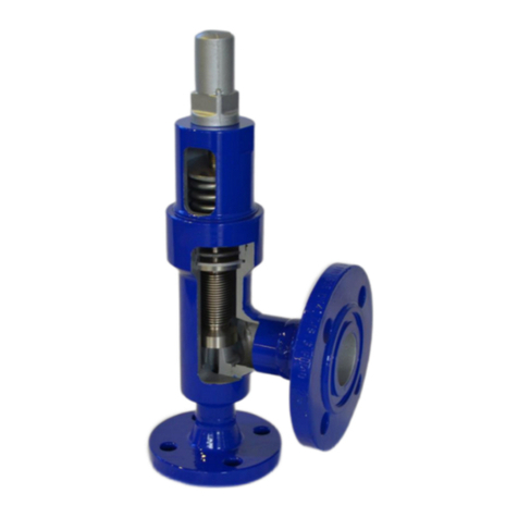
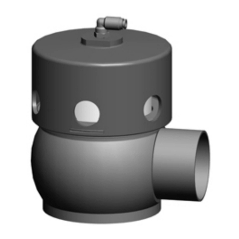
GEA DHV DN65/50 KVS 16 User manual

Manual de instruções / Operating Instructions
Válvula de retenção de pressão DHV
Constant Pressure Valve DHV
Edição/Issue 2016-01
Português/English
GEA Mechanical Equipmentengineering for a better world

2016-01 · Válvula de retenção de pressão DHV / Constant pressure Valve DHV

1
2016-01 · Válvula de retenção de pressão DHV / Constant pressure Valve DHV 1
Índice
Introdução
Nome e endereço do fabricante ........................ 2
Identificação das válvulas Tuchenhagen ............ 2
Abreviaturas e termos importantes ...................... 3
Instruções de segurança ........................................ 5
Utilização adequada............................................ 5
Pessoal .................................................................. 5
Modificações, peças de substituição,
acessórios ............................................................ 5
Instruções gerais .................................................. 5
Identificação das instruções de segurança
no manual de instruções .................................... 6
Outros símbolos .................................................. 6
Zonas de especial perigo .................................... 7
Utilização específica ................................................ 7
Transporte e armazenamento ................................ 8
Verificar o fornecimento .................................... 8
Pesos .................................................................... 8
Transporte ............................................................ 8
Armazenamento.................................................. 8
Dimensionamento da válvula de retenção
de pressão................................................................ 9
Estrutura .............................................................. 14
Montagem e operação.......................................... 14
Posição de montagem ...................................... 14
Válvula com elementos separáveis
de união de tubos ............................................ 15
Válvula com bocal de soldar ............................ 15
Conexão pneumática ........................................ 16
Colocação em funcionamento.......................... 16
ffff .......................................................................... 17
Avarias, causas, soluções ...................................... 19
Manutenção .......................................................... 19
Inspecções .......................................................... 19
Intervalos de manutenção ................................ 20
Antes de desmontar .......................................... 21
Desmontagem .................................................. 21
Manutenção........................................................ 22
Montagem .......................................................... 23
Dados técnicos ...................................................... 24
Conexões de tubos – Sistema VARIVENT®........ 25
Ferramenta/lubrificante ....................................25
Resistência dos materiais de vedação .............. 26
Anexo
Lista de peças de substituição/ficha de dimensões
Declaração de incorporação
1
Contents
Introduction
Manufacturer’s name and address .................... 2
Identification of Tuchenhagen valves ................ 2
Important Abbreviations and terms ...................... 3
Safety instructions .................................................. 5
Designated use .................................................... 5
Personnel.............................................................. 5
Modifications, spare parts, accessories .............. 5
General instructions ............................................ 5
Marking of safety instructions in the
operating manual................................................ 6
Further symbols .................................................. 6
Special hazardous spots ...................................... 7
Designated use ........................................................ 7
Transport and Storage ............................................ 8
Checking the consignment ................................ 8
Weights ................................................................ 8
Transport .............................................................. 8
Storage ................................................................ 8
Sizing of constant pressure valves ...................... 9
Design .................................................................. 14
Assembly and Operation ...................................... 14
Installation position .......................................... 14
Valve with detachable housing connections .. 15
Valve with welded connections ........................ 15
Pneumatic connections .................................... 16
Commissioning .................................................. 16
Cleaning and Passivation .................................... 17
Malfunction, Cause, Remedy................................ 19
Maintenance .......................................................... 19
Inspections .......................................................... 19
Maintenance intervals........................................ 20
Prior to dismantling the valve .......................... 21
Dismantling ........................................................ 21
Maintenance ...................................................... 22
Assembling.......................................................... 23
Technical Data ........................................................ 24
Pipe connections – VARIVENT®system ............ 25
Tools / Lubricant ................................................ 25
Resistance of the sealing material.................... 26
Annex
Spare parts list/Dimension sheet
Declaration of Incorporation
22016-01 · Válvula de retenção de pressão DHV / Constant pressure Valve DHV
2
Introdução
Nome e endereço
do fabricante
GEA Tuchenhagen GmbH
Am Industriepark 2-10
D-21514 Büchen
Germany
Morada:
Berliner Straße 25
D-21514 Büchen
Germany
Tel.: +49-(0)41 55 / 49 2402
Fax: +49(0)41 55 / 49 2428
E-Mail: sales.g[email protected]
www.tuchenhagen.com
Identificação das
válvulas Tuchenhagen
As válvulas Tuchenhagen possuem uma placa de carac-
terísticas. Esta encontra-se na tampa do cilindro.
Em cada encomenda de peças de substituição ou em
cada correspondência, indique a designação completa
da válvula.
Neste manual de instruções são descritas as válvulas
Tuchenhagen com as seguintes combinações de letras
(ver círculo):
DHV
Introduction
Manufacturer’s name
and address
GEA Tuchenhagen GmbH
Am Industriepark 2-10
D-21514 Büchen
Germany
House address:
Berliner Straße 25
D-21514 Büchen
Germany
Phone.: +49-(0)41 55 / 49 2402
Fax: +49(0)41 55 / 49 2428
E-Mail: sales.g[email protected]
www.tuchenhagen.com
Identification of
Tuchenhagen valves
Tuchenhagen valves are fitted with a type plate located
on the cylinder cover.
Please specify the complete valve identification code in
all correspondence and when ordering spare parts.
In these operating instructions, the Tuchenhagen valves
are designated with the following letter combinations
(see circle above):

3
2016-01 · Válvula de retenção de pressão DHV / Constant pressure Valve DHV 3
Abreviaturas e
termos importantes
BS Norma britânica
bar Unidade de medida da pressão
Todas as indicações de pressão [bar/psi] desig-
nam a sobrepressão [barg/psig] desde que não
seja explicitamente descrito nada em contrário.
aprox. aproximadamente
°C Unidade de medida da temperatura
Graus Celsius
dm3nUnidade medida do volume
Decímetro cúbico
Volume de norma (litros de norma)
1dm
3n= 1 ln≈ 61 inch3
DN Diâmetro nominal DIN
DIN Norma alemã de
DIN Deutschen Institut für Normung e.V.
EN Norma Europeia
EPDM Designação do material
Abreviatura conforme DIN/ISO 1629
Borracha de etilenopropilenodieno
°F Unidade de medida da temperatura
Graus Fahrenheit
FKM Designação do material
Abreviatura conforme DIN/ISO 1629
Borracha fluorocarbonada
h Unidade de medida do tempo
Horas
HNBR Designação do material
Abreviatura conforme DIN/ISO 1629
Borracha de acrilonitrilo-butadieno hidrogenado
IP Tipo de protecção
ISO Norma internacional da
Organização Internacional de Normalização
kg Unidade de medida do peso
Quilograma
kN Unidade de medida da força
Quilonewton
Valor Kv do coeficiente de débito [m³/s]
1 KV = 0,86 x Cv
l Unidade de medida do volume
Litro
Important Abbrevia-
tions and Terms
BS British standard
bar Unit of measure for pressure
All pressure ratings [bar/psi] stand for
over pressure [barg/psig] if this is not explicitly
described differently.
approx. approximately
°C Unit of measure for temperature
degrees centigrade
dm3nUnit of measure for volume
cubic decimetre
Volume (litre) under standard conditions
1dm
3n= 1 ln≈ 61 inch3
DN DIN nominal width
DIN Deutsche Norm (German standard)
DIN Deutsches Institut für Normung e.V.
(German institut for Standardization)
EN European standard
EPDM Material designation
Short designation acc. to DIN/ISO 1629
Ethylene propylene diene (monomer) rubber
°F Unit of measure for temperature
degrees Fahrenheit
FKM Material designation
Short designation acc. to DIN/ISO 1629
Fluorine rubber
h Unit of measure for time
hour
HNBR Material designation
Short designation acc. to DIN/ISO 1629
Hydrated acrylonitrile butadiene rubber
IP Protection class
ISO International standard of the
International Organization for Standardization
kg Unit of measure for weight
kilogram
kN Unit of measure for force
kilo Newton
Cv-Wert flow coefficient [US gallons per minute]
1 Cv = 1,17 x Kv
l Unit of measure for volume
litre

42016-01 · Válvula de retenção de pressão DHV / Constant pressure Valve DHV
máx. máximo
mm Unidade de medida do comprimento
Milímetro
μm Unidade de medida do comprimento
Micrómetro
M métrico
Nm Unidade de medida do trabalho
Newton-metro
Dados para o binário de aperto
1 Nm = 0,737 lb.ft.
Pound-Force/libra-força (lb) + Feet/Pés (ft)
PA Poliamida
PE-LD Polietileno de baixa densidade
PTFE Politetrafluoretileno
psi Unidade de medida da pressão
Todas as indicações de pressão [bar/psi] desig-
nam a sobrepressão [barg/psig] desde que não
seja explicitamente descrito nada em contrário.
SET-UP Instalação com função de auto-aprendizagem
Durante a colocação em funcionamento e a
manutenção, o SET-UP realiza todos os ajus-
tes necessários para gerar mensagens.
SW Indicação para o tamanho da chave de ferra-
mentas
Abertura da chave
v. cap. ver capítulo
v. fig. ver figura
T.VIS®Tuchenhagen Ventil Informations-System
(sistema de informação sobre válvulas
Tuchenhagen)
V DC Volt direct current = corrente contínua
V AC Volt alternating current = corrente alternada
W Unidade de medida da potência
Watts
TIG Processo de soldadura
Soldadura pelo arco voltaico em atmosfera
inerte com eléctrodo de tungsténio
Polegadas Unidade de medida do comprimento
no espaço linguístico inglês
Polegadas Dimensão do tubo segundo a Norma
OD Britânica (BS), Outside Diameter
(diâmetro externo)
Polegadas Dimensão do tubo segundo a norma
IPS americana
Iron Pipe Size
max. maximum
mm Unit of measure for length
millimetre
μm Unit of measure for length
micrometre
M metric
Nm Unit of measure for work
Newton metre
Unit for torque
1 Nm = 0.737 lb.ft.
Pound-Force (lb) + Feet (ft)
PA Polyamide
PE-LD Polyethylene low density
PTFE Polytetrafluoroethylene
psi Unit of measure for pressure
All pressure ratings [bar/psi] stand for
over pressure [barg/psig] if this is not explicitly
described differently.
SET-UP Self-learning installation
For commissioning and maintenance the
SET-UP procedure carries out all necessary
settings for the generation of messages.
Size Size of spanners
(width across flats)
see Chapt. see Chapter
s. ill. see illustration
T.VIS®Tuchenhagen Valve Information System
V DC Volt direct current
V AC Volt alternating current
W Unit of measure for
Watt
TIG Welding method
tungsten inert-gas welding
Inch Unit of measure for length
in English-speaking countries
Inch OD Pipe dimension acc. to British standard (BS),
Outside Diameter
Inch IPS US pipe dimension
Iron Pipe Size

5
2016-01 · Válvula de retenção de pressão DHV / Constant pressure Valve DHV 5
Instruções de segurança
Utilização adequada
A válvula foi concebida apenas para a utilização especí-
fica descrita. Qualquer outra utilização será considerada
utilização inadequada.
A GA Tuchenhagen não se responsabiliza por danos
resultantes de uma utilização indevida; a entidade
exploradora é a única responsável.
As condições para uma operação correcta e segura da
válvula são um transporte e armazenamento adequa-
dos, assim como uma instalação e montagem realizada
por técnicos competentes.
Uma utilização adequada inclui também o cumprimento
das instruções de operação, manutenção e inspecção.
Pessoal
O pessoal responsável pela operação e manutenção tem
de dispor de qualificação adequada para a realização
destes trabalhos. Deve ainda ser informado sobre possí-
veis perigos e conhecer e cumprir as instruções de segu-
rança indicadas na documentação.
Os trabalhos no sistema eléctrico só devem ser realiza-
dos por electricistas qualificados.
Modificações, peças de
substituição, acessórios
É proibido efectuar modificações e conversões não auto-
rizadas que afectem a segurança da válvula.
Os dispositivos de segurança não podem ser anulados,
removidos ou inactivados.
Utilizar apenas peças de substituição originais e acessó-
rios autorizados pelo fabricante.
Instruções gerais
O utilizador só deve utilizar a válvula se esta estiver em
perfeito estado.
Além das instruções presentes nesta documentação, são
válidas também as
– Normas aplicáveis de prevenção de acidentes
– Normas técnicas de segurança geralmente aceites
– Regulamentações nacionais do país de utilização
– Instruções de trabalho e de segurança internas
da empresa.
– Normas de montagem e de operação para a utilização
em atmosferas potencialmente explosivas.
Safety Instructions
Designated use
The valve is designed exclusively for the purposes
described below. Using the valve for purposes other
than those mentioned is considered contrary to its desig-
nated use. GEA Tuchenhagen cannot be held liable for
any damage resulting from such use; the risk of such
misuse lies entirely with the user.
The prerequisite for the reliable and safe operation of
the valve is proper transportation and storage as well as
competent installation and assembly.
Operating the valve within the limits of its designated
use also involves observing the operating, inspection
and maintenance instructions.
Personnel
Personnel entrusted with the operation and mainte-
nance of the valve must have the suitable qualification
to carry out their tasks. They must be informed about
possible dangers and must understand and observe the
safety instructions given in the relevant manual. Only
allow qualified personnel to make electrical connections.
Modifications, spare parts,
accessories
Unauthorized modifications, additions or conversions
which affect the safety of the valve are not permitted.
Safety devices must not be bypassed, removed or made
inactive.
Only use original spare parts and accessories recom-
mended by the manufacturer.
General instructions
The user is obliged to operate the valve only when it is
in good working order.
In addition to the instructions given in the operating
manual, please observe the following:
– relevant accident prevention regulations
– generally accepted safety regulations
– regulations effective in the country of installation
– working and safety instructions effective in the user's
plant.
– Installation and operating instructions within poten-
tially explosive areas.

62016-01 · Válvula de retenção de pressão DHV / Constant pressure Valve DHV
Símbolo Termo de Significado
advertência
PERIGO Perigo iminente, que pode
provocar ferimentos gra-
ves ou a morte.
CUIDADO Situação perigosa, que
pode provocar ferimentos
leves ou danos materiais.
Ao trabalhar em atmosfe-
ras potencialmente explo-
sivas, é imprescindível res-
peitar as instruções de
colocação em funciona-
mento e de manutenção.
Outros símbolos
Símbolo Significado
• Passos de trabalho ou de operação
a realizar na sequência indicada.
✗NOTA Informações relativas à utilização
óptima da válvula
– Enumeração geral
Identificação das
instruções de segurança
no manual de instruções
As instruções de segurança especiais encontram-se sem-
pre antes das respectivas instruções de utilização. São
evidenciadas através de um símbolo de perigo e um
termo de advertência.
Ler e respeitar sempre o texto que acompanha estes
símbolos , antes de prosseguir com a leitura do texto e
utilização da válvula.
Marking of safety
instructions in the
operating manual
Special safety instructions are given directly before the
operating instructions. They are marked by the follow-
ing symbols and associated signal words.
It is essential that you read and observe the texts belong-
ing to these symbols before you continue reading the
instructions and handling the valve.
Symbol Signal Meaning
word
DANGER Imminent danger, which
may cause severe bodily
injury or death.
CAUTION Dangerous situation, which
may cause slight injury or
damage to material.
When working in poten-
tially explosive atmos-
pheres, strictly observe the
instructions for commis-
sioning and maintenance
Further symbols
Symbol Meaning
• Process / operating steps which
must be performed in the specified
order.
NOTE Information as to the optimum use
of the valve
– General enumeration

7
2016-01 · Válvula de retenção de pressão DHV / Constant pressure Valve DHV 7
Zonas de
perigo
especiais
PERIGO
Em caso de avaria,
desligar a válvula (da cor-
rente e da alimentação de
ar) e garantir que não
pode ser reactivada.
Eliminar a avaria de ime-
diato.
Nunca aceder ao acciona-
mento em (X) e à caixa da
válvula (404).
Special
hazardous
spots
DANGER
In the event of malfunc-
tions set the valve out of
operation (disconnect the
valve from the power and
the air supply) and secure
it against reactivation.
Immediately rectify the
fault.
Never put your hand into
the actuator at (X) or into
the valve housing (404).
X
Utilização específica
A válvula de retenção de pressão DHV é utilizada para a
manutenção constante de uma pressão de entrada pre-
viamente seleccionada.
A válvula de retenção de pressão DHV é um componen-
te de manutenção de pressão (sem função de segurança)
na acepção da directiva relativa aos equipamentos sob
pressão: Directiva 97/23/CE. Estas válvulas estão classi-
ficadas de acordo com o ponto 3 do artigo 3.º do Anexo II.
Em caso de divergência, será enviada uma declaração
de conformidade especial.
Designated Use
The DHV constant pressure valve is designeted to main-
tain the inlet pressure at constant level.
The DHV constant pressure valve is a pressure keeping
equipment part (without safety function) in the sense of
the pressure equipment directive 97/23/EC. They are
classified according to Appendix II in Article 3, Section 3.
In case of deviations thereof, a separate Declaration of
Conformity will be supplied.
404
404

82016-01 · Válvula de retenção de pressão DHV / Constant pressure Valve DHV
Transporte e
armazenamento
Verificar o fornecimento
Na recepção da válvula, verificar se
– Os números de tipo e de série na placa de característi-
cas correspondem aos dados dos documentos de
encomenda e fornecimento,
– O equipamento está completo e todas as peças estão
em boas condições.
Os danos visíveis provocados durante o transporte
e/ou embalagens em falta devem ser registados de ime-
diato na guia de remessa da transportadora.
O consignatário deve exigir de imediato por escrito
uma indemnização à transportadora e informar a
Tuchenhagen acerca da situação. Os danos não imedia-
tamente visíveis devem ser comunicados à transporta-
dora num período de 6 dias. O consignatário é respon-
sável pela reclamação dos danos após este prazo.
Pesos
Tamanho Peso
DN 40 aprox. 2 kg
DN 65 aprox. 7 kg
1,5 " OD aprox. 2 kg
2,5 " OD aprox. 7 kg
Transporte
PERIGO
As unidades de embalagem/válvulas só devem ser
transportadas com sistemas de elevação e ganchos ade-
quados. Respeitar os símbolos na embalagem.
Transportar a válvula com cuidado, para evitar danos
provocados por golpes ou cargas e descargas efectuadas
sem as devidas precauções.
Armazenamento
As válvulas, os machos das válvulas ou as peças de
substituição devem ser armazenados secos, sem vibra-
ções e sem pó, no sentido de, tanto quando possível,
evitar danos na embalagem original.
Se a válvula tiver sido submetida a temperaturas ≤0 °C
durante o transporte ou o armazenamento, deve ser
armazenada temporariamente para evitar danos. Antes
do manuseamento (desmontagem da caixa / activação
dos accionamentos), recomendamos um armazenamen-
to de 24 h a uma temperatura ≥5 °C, para que os cristais
de gelo possivelmente causados pela água de condensa-
ção possam desaparecer.
Transport and
Storage
Checking the consignment
On receipt of the valve check whether the
– type and serial number on the type plate correspond
to the data in the order and delivery documents and
– the equipment is complete and all components are in
good order.
The forwarding agent must immediately be notified of
any transport damage detectable from the outside
and/or missing packages (confirmation on the consign-
ment note). The consignee shall take recourse against
the forwarding agent immediately in writing and
inform Tuchenhagen accordingly.
Transport damages which cannot be recognized imme-
diately shall be brought to the forwarder´s notice within
6 days. Later claims on damages shall be born by the
consignee.
Weights
Size Weight
DN 40 approx. 2 kg
DN 65 approx. 7 kg
1,5 " OD approx. 2 kg
2,5 " OD approx. 7 kg
Transport
DANGER
For transport of the package units/valves only use suit-
able lifting gears and slings. Observe the instruction
symbols on the package and on the valve.
Handle the valve with care to avoid damage caused by
shock or careless on- and unloading.
Storage
Valves, valve inserts or spare parts should be stored in a
dry place, free of vibrations and dust. To avoid damage,
leave the components in their original packaging if pos-
sible.
In the case that during transport or storage the valve
was exposed to temperatures ≤0 °C, it must be stored
in a dry place against damage.
We recommend, prior to any handling (dismounting
the housings / activation of actuators) an intermediate
storage of 24 h at a temperature of ≥5 °C so that any ice
crystals formed by condensation water may melt.

9
2016-01 · Válvula de retenção de pressão DHV / Constant pressure Valve DHV 9
Dimensionamento da
válvula de retenção
de pressão
Para o dimensionamento do tamanho da válvula (largura
nominal ou valor Kv) são necessários os seguintes dados:
- Pressão do produto [barg]
- Fluxo volumétrico [m3/h]
Estes valores são retirados dos diagramas para determi-
nar o ponto de intersecção (ponto de funcionamento). O
ponto de funcionamento deve situar-se no "intervalo de
funcionamento" da válvula.
Exemplo: entrada 4 barg, 27 m³/h
O intervalo de funcionamento define-se como o interva-
lo em que a válvula regula uma pressão, ou seja, o inter-
valo onde o prato da válvula se encontra entre a posição
final inferior (fechada) e a posição final superior
(completamente aberta).
Em conclusão inversa, o intervalo inadmissível assinala
o intervalo onde a válvula está completamente aberta e
não pode ocorrer mais nenhuma regulação.
The operating range is the range in which the valve reg-
ulates a pressure, ie the area where the piston is between
the bottom (closed) and upper (fully open) position.
Conversely, the "out of range" area indicates where the
valve is fully open and no more regulation is possible.
Sizing of constant
pressure valves
Sizing of the valves size requires the following data:
- product pressure [barg]
- volume flow [m3/h]
The parameters have to be inscribed in the diagram, to
determine the point of intersection (operating point).
The operating point must be in the "operating range" of
the valve.
Example: 4 barg, 27 m³/h
Pressão do produto na entrada (bar) / Product pressure inlet [bar]
Fluxo volumétrico [m³/h] / Flow rate [m³/h]
Pressão do ar no
accionamento /
Air pressure actuator
Intervalo de funcionamento / operating range
Intervalo inadmissível /
out of range
Válvula muito pequena, inadmissível /
Valve size to small, not permitted

10 2016-01 · Válvula de retenção de pressão DHV / Constant pressure Valve DHV
10
Se o tamanho da válvula estiver determinado, ainda
deve ser definida a pressão de ar a ajustar. Esta aumenta
com o aumento de pressão de produto, tal como se
segue (setas verdes):
As barras assinalam as pressões de entrada da válvula
de retenção de pressão, conforme a pressão do produto.
Se a pressão do produto aumentar, a pressão de entrada
também aumenta.
O diagrama indica apenas valores indicativos que,
durante o funcionamento, devem ser verificados e, se
necessário, reajustados.
Para o exemplo seleccionado foi escolhida uma válvula
DN65/50 KVS 16, à qual deve ser ajustada uma pressão
de entrada de cerca de 2 barg.
The bars indicate air supply pressures for constant pres-
sure valve, depending on product pressure. Increases
the product pressure, also increases the air supply
pressure.
The diagram shows only reference values, which should
be examined during the operation and, if necessary
readjusted.
For the example a valve DN65/50 KVS16 was chosen,
where a supply pressure of approx. 2 barg need to
be set.
Is the size of the valve determines, need the air pressure
also be determined. The air pressure increases with
increasing product pressure, as follows (green arrows):
Pressão do produto na entrada (bar) / Product pressure inlet [bar]
Fluxo volumétrico [m³/h] / Flow rate [m³/h]
Intervalo inadmissível /
out of range
Intervalo de funcionamento / operating range
Pressão do ar no
accionamento /
Air pressure actuator
Intervalos de utilização recomendados para as válvulas (conforme a pressão de ar de comando)
Recommended operating range (depending on air pressure)
Kvs Intervalo de utilização / Operating range (l/h)
4250 ... 10.000
10 1.500 ... 29.000
16 2.500 ... 40.000
25 5.000 ... 65.000
35 7.000 ... 90.000
60 10.000 ... 100.000

11
2016-01 · Válvula de retenção de pressão DHV / Constant pressure Valve DHV 11
Fluxo volumétrico [m³/h] / Flow rate [m³/h] Pressão do ar no
accionamento /
Air pressure actuator
Pressão do produto na entrada (bar) / Product pressure inlet [bar]
Fluxo volumétrico [m³/h] / Flow rate [m³/h] Pressão do ar no
accionamento /
Air pressure actuator
Pressão do produto na entrada (bar) / Product pressure inlet [bar]

12 2016-01 · Válvula de retenção de pressão DHV / Constant pressure Valve DHV
12
Pressão do ar no
accionamento /
Air pressure actuator
Fluxo volumétrico [m³/h] / Flow rate [m³/h]
Pressão do produto na entrada (bar) / Product pressure inlet [bar]
Pressão do ar no
accionamento /
Air pressure actuator
Fluxo volumétrico [m³/h] / Flow rate [m³/h]
Pressão do produto na entrada (bar) / Product pressure inlet [bar]

13
2016-01 · Válvula de retenção de pressão DHV / Constant pressure Valve DHV 13
Pressão do ar no
accionamento /
Air pressure actuator
Fluxo volumétrico [m³/h] / Flow rate [m³/h]
Pressão do produto na entrada (bar) / Product pressure inlet [bar]
Pressão do ar no
accionamento /
Air pressure actuator
Fluxo volumétrico [m³/h] / Flow rate [m³/h]
Pressão do produto na entrada (bar) / Product pressure inlet [bar]

14 2016-01 · Válvula de retenção de pressão DHV / Constant pressure Valve DHV
Montagem e
operação
Assegurar que:
– A válvula é montada livre de tensão no sistema
de tubagens e
– Não se encontram objectos estranhos no sistema (por
ex. ferramentas, parafusos).
Posição de montagem
A posição de montagem da válvula é a vertical.
Deve ser assegurado que a caixa da válvula e o
sistema de tubulação podem funcionar bem em vazio.
NOTA
Outras posições de montagem alteram ligeiramente a
função da válvula. Será necessária uma pressão do ar
ligeiramente superior para realizar a função. Além
disso, a válvula poderá não esvaziar totalmente em fun-
ção da posição de montagem. É favor observar.
Assembly and
Operation
Make sure that
– the valve is installed in the pipe system free of stress
and
– no foreign materials (e. g. tools, bolts, lubricants) are
enclosed in the system.
Installation position
The standard installation position of the valve is upright.
Care must be taken to ensure that the valve housing and
the pipe system can drain properly.
NOTE
Other installation positions will slightly alter the func-
tion of the valve. A minimally higher air pressure will be
necessary to perform the function. It is also possible that
the valve cannot drain completely in certain installation
positions.
Estrutura
1 Anel de vedação
10 Anel de retenção
15 Disco da válvula DHV
29 O-Ring
117 Conexão de encaixe
roscada angular
140 Tampa do cilindro
DHV
404 Caixa DHV
opcional
118 Conexão de ar com
purgador rápido
Favorece o ajuste mais
rápido de ar comprimido
por cima do disco
da válvula
Design
1 sealing ring
10 Snap ring
15 valve disk DHV
29 O-ring
117 angular union
140 cylinder cover DHV
404 housing DHV
optional
118 Air connection with
quick vent valve
Supports faster pressure
balancing above the valve
disk
1
140
29
117
404
15
10
118
Sentido do fluxo/
Flow direction

15
2016-01 · Válvula de retenção de pressão DHV / Constant pressure Valve DHV 15
Válvula com elementos re-
movíveis de união de tubos
PERIGO
Se as tubagens contiverem líquidos, estes podem
salpicar quando as mesmas são abertas e causar feri-
mentos. Por isso, antes de desapertar as uniões de tubos
e semi-anéis:
– Esvaziar a tubagem e, se necessário, limpá-la ou enxa-
guá-la.
– Separar a secção de tubagem da válvula a montar do
resto do sistema de tubagens para impedir a reentra-
da do produto.
As válvulas com elementos separáveis de união de
tubos podem ser montadas directamente no sistema de
tubagens se forem usados os acessórios adequados.
Válvula com bocal
de soldar
CUIDADO
Para os trabalhos de soldadura é necessário retirar da
caixa da válvula todas as peças de montagem.
Todas as superfícies do disco da válvula são superfícies
funcionais.
Remover o disco da válvula da caixa sem danos e arma-
zenar em segurança.
• Lavar a caixa por dentro com uma mistura de hidrogé-
nio e azoto para retirar o oxigénio do sistema.
• Encaixar a caixa e fixá-la.
• Utilizar a soldadura TIG com corrente pulsada.
• Soldar a caixa, se necessário com aditivo de soldadura,
no sistema de tubos.
• Depois de soldar, passivar a costura.
CUIDADO
Ao montar a válvula, substituir sempre os O-Rings
da caixa, para garantir mais tarde a estanquidade
da válvula.
• Colocar as juntas.
• Montar a válvula.
Valve with detachable
housing connections
DANGER
If liquids are running in the pipe system, they can gush
out when the line is opened and cause injury to people.
Therefore, prior to detaching pipe connection fittings or
clamp connections:
– drain and – if necessary – rinse or clean the pipe.
– disconnect the pipe segment with the valve to be
mounted from the rest of the pipe system to secure the
pipe against incoming product.
Valves with detachable housing connections can be in-
stalled directly into the pipe system, if suitable connec-
tion fittings are used.
Valve with welded
connections
CAUTION
For welding operations, all internals must be removed
from the valve housing.
All valve disk surfaces are functional surfaces.
Remove the valve disk from the housing without dama-
ging it and put it away safely.
• Purge the housing on the inside with forming gas to
remove oxygen from the system.
• Fit in the housing and tack it.
• Use the TIG welding method with pulsating current.
• Weld the housing into the pipe system, if necessary
using a welding filler.
• After welding, passivate the seam.
CAUTION
When mounting the valve, make sure that the O-rings in
the housing are replaced to ensure the tightness
of the valve.
• Insert the seals.
• Mount the valve.

16 2016-01 · Válvula de retenção de pressão DHV / Constant pressure Valve DHV
16
Conexão pneumática
Ar necessário
A necessidade de ar para o processo de comutação é de
0,2 dm3n/curso.
– KVS 4 - 10: 0,06 dm3n/curso
– KVS 16 - 60: 0,21 dm3n/curso
Montar a mangueira de ar
NOTA
Para encaixar bem a conexão de ar, é necessário cortar as
mangueiras pneumáticas em linha recta com um corta-
dor de tubos.
• Fechar o abastecimento de ar comprimido.
• Inserir a mangueira de ar na conexão de ar do módulo
de controlo.
• Abrir novamente o abastecimento de ar comprimido.
Colocação em
funcionamento
• Garantir que não se encontram objectos estranhos no
sistema.
• Ligar uma vez a válvula, activando-a com ar compri-
mido.
• Limpar o sistema de tubagens antes da primeira intro-
dução dos produtos.
• Durante a colocação em funcionamento controlar
regularmente se há fugas nas juntas. Substituir as jun-
tas danificadas.
NOTA
A GEA Tuchenhagen recomenda a utilização de um
regulador de pressão de precisão, com ventilação trasei-
ra, no abastecimento de ar comprimido.
Pneumatic Connections
Air requirement
The compressed air required for switching operations of
the valve is 0.2 dm3n/stroke.
– KVS 4 upto 10 0,06 dm3n/stroke
– KVS 16 upto 60 0,21 dm3n/stroke
Installing the air hose
NOTE
To ensure optimum fit in the air connector, the pneuma-
tic hoses must be cut square with a hose cutter.
• Shut off the compressed air supply.
• Push the air hose into the air connector in the control
module.
• Reopen the compressed air supply.
Commissioning
• Make sure that no foreign materials are enclosed in
the system.
• Actuate the valve once by applying compressed air.
• Prior to the first product run clean the pipe system.
• During commissioning, regularly check the seals for
leakage. Replace defective seals.
NOTE
GEA Tuchenhagen recommends that a pressure regula-
tor with integrated flow function should be provided in
the compressed air supply.

17
2016-01 · Válvula de retenção de pressão DHV / Constant pressure Valve DHV
Cleaning and
Passivation
Cleaning
All parts in contact with product must be cleaned at
regular intervals. Always observe the safety data sheets
issued by the cleaning agent manufacturers. Only use
cleaning agents which do not cause damage to the seals
and the inner parts of the valve. When the pipe is clea-
ned, the cleaning medium also flows through and cle-
ans the valve housings.
It is recommend to deactivate the control air pressure
during cleaning to achieve an optimal cleaning result.
With respect to the cleaning method and parameters
like detergents, temperatures, times and intervals, the
component manufacturer can merely make recommen-
dations but cannot provide any generally applicable
details. Method and parameters should be determined
and defined by the operator in accordance with the rele-
vant process.
The cleaning effect must be checked regularly by the
operator!
Cleaning Process Examples
Typical cleaning parameters in dairy opera-
tions
Example of a two-phase cleaning process:
• Sodium hydroxide and combination products based
on sodium hydroxide in concentrations from 0.5 % to
2.5 % at 75 °C to 80 °C.
• Phosphoric acid or nitric acid and combination pro-
ducts based on these acids in concentrations from 0.3
to 1.5 % at approx. 65 °C.
Example of a cleaning operation in one cleaning step:
• Formic acid and combination products based on for-
mic acid at up to 85 °C.
Typical cleaning parameters in breweries
• Sodium hydroxide and combination products based
on sodium hydroxide in concentrations from
1 % to 4 % at approx. 85 °C.
• Phosphoric acid or nitric acid and combination pro-
ducts based on these acids in concentrations from
0.3 to 1.5 % at 20 °C.
Limpeza e
passivação
Limpeza
Todas as peças que entram em contato com o produto
têm de ser limpas regularmente. Aqui devem ser obser-
vadas as fichas técnicas de segurança dos fabricantes
dos produtos de limpeza. Só podem ser utilizados pro-
dutos de limpeza que não danificam as vedações e as
peças internas da válvula. As caixas das válvulas são
também enxaguadas e limpas durante a limpeza das
tubulações.
Para um resultado de limpeza ideal, recomendamos que
desative a pressão de ar de comando para a válvula
durante a limpeza.
Relativamente ao tipo e modo de limpeza, como por
exemplo os produtos de limpeza, a temperatura, os tem-
pos e os intervalos, o fabricante do componente poderá
fornecer meramente uma recomendação, mas nenhuma
indicação obrigatória. Isso deverá ser apurado e deter-
minado pela entidade operadora em função do respec-
tivo processo.
O sucesso da limpeza deverá, assim, ser regularmente
verificado pela entidade operadora!
Exemplos de limpeza
Parâmetros de limpeza habituais em fábri-
cas de laticínios
Exemplo de uma limpeza bifásica:
• Impregnar lixívia de soda cáustica e produtos combi-
nados à base de lixívia de soda cáustica em concentra-
ções de 0,5 % até 2,5 % a 75 °C até 80 °C.
• Ácido fosfórico ou ácido nítrico e produtos combina-
dos à base dos mesmos nas concentrações de 0,3 até
1,5 % a aprox. 65 °C.
Exemplo de uma limpeza em um processo de limpeza:
• Ácido fórmico e produtos combinados à base de ácido
fórmico a até 85 °C.
Parâmetros de limpeza habituais em fábri-
cas de cerveja
• Lixívia de soda cáustica e produtos combinados à
base de lixívia de soda cáustica em concentrações de 1
% até 4 % a aprox. 85 °C.
• Ácido fosfórico ou ácido nítrico e produtos combina-
dos à base dos mesmos nas concentrações de 0,3 até
1,5 % a 20 °C.

18 2016-01 · Válvula de retenção de pressão DHV / Constant pressure Valve DHV
Cleaning Effect
The cleaning effect depends on the following factors:
• Temperature
•Time
• Mechanics
• Chemicals
• Degree of soiling
These factors can be combined in such a way as to make
an optimal cleaning result probable. Depending on the
cleaning method (medium, concentration, temperature
and contact times), the seals are affected to different
degrees. This can impair the function and the service
life.
Passivation
Before commissioning a plant, passivation is commonly
carried out for long pipes and tanks.
Valve blocks are usually excepted from this. Passivation
is typically performed using nitric acid (HNO3) at
approx. 80 °C (176 °F) at a concentration of 3 % and a
contact time of 6 to 8 hours.
Sucesso da limpeza
O sucesso da limpeza depende dos seguintes fatores:
• Temperatura
• Tempo
• Mecânica
• Química
• Grau de sujeira
A partir destes fatores poderão ser formadas várias com-
binações que tornam possível um sucesso aceitável da
limpeza. Dependendo do método de limpeza (fluido,
concentração, temperatura e tempos de contato), as
vedações são agredidas em diferentes graus. Isso poderá
causar prejuízos no funcionamento e na vida útil.
Passivação
Antes da colocação em funcionamento de uma
instalação é realizada, normalmente, uma passivação em
tubulações longas e tanques.
Por regra, os blocos de válvulas não são abrangidos. A
mesma é realizada, geralmente, com ácido nítrico
(HNO3) a aprox. 80 °C (176 °F) com uma concentração
de 3% e um tempo de contato entre 6 a 8 horas.
Other manuals for DHV DN65/50 KVS 16
1
This manual suits for next models
5
Table of contents
Other GEA Control Unit manuals

GEA
GEA Aseptomag GD User manual

GEA
GEA AVR Series User manual

GEA
GEA VARIVENT K User manual

GEA
GEA VARIVENT Y User manual

GEA
GEA VARIVENT X User manual

GEA
GEA VARIVENT MT/T R 08 User manual

GEA
GEA Aseptomag RVIN User manual

GEA
GEA Aseptomag AV User manual

GEA
GEA VARIVENT K User manual

GEA
GEA VARIVENT TSVN User manual