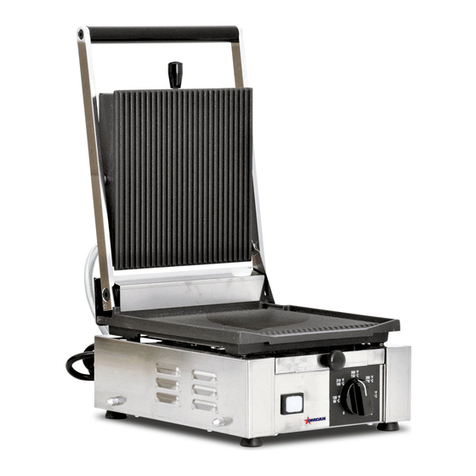
Omcan OGC-24 User manual

Counter Top Gas Char Broiler
Models OGC-24, OGC-36, OGC-48
Instruction Manual
1-800-465-0234
www.omcan.com
3115 Pepper Mill Court, Mississauga, ON, L5L 4X5
1889 Maryland Avenue, Niagara Falls, NY, 14305
Version 1

2
Page
-------------------------------------------------------------------------------- 3
---------------------------------------------------------------------------------- 3
---------------------------------------------------------------------- 4 - 5
--------------------------------------------------------------------------------------- 6 - 7
--------------------------------------------------------------------------------------------- 8
----------------------------------------------------------------------------------------- 8
--------------------------------------------------------- 9 - 12
---------------------------------------------------------------------------- 13 - 14
---------------------------------------------------------------------------- 15
Table of Contents
Section
General Information
Safety & Warranty
Technical Specications
Installation
Operation
Maintenance
Instructions for Field Conversion
Parts Breakdown
Warranty Registration
Model OGC-24 / Model OGC-36 / Model OGC-48

3
General Information
Safety & Warranty
Omcan Manufacturing and Distributing Company Inc. and Food Machinery Of America, Inc. dba Omcan
are not responsible for any harm or injury caused due to any person’s improper or negligent use of
this equipment. The product shall only be operated by someone over the age of 18, of sound mind, and
not under the inuence of any drugs or alcohol, who has been trained in the correct operation of this
machine, and is wearing authorized, proper safety clothing. Any modication to the machine voids any
warranty, and may cause harm to individuals using the machine or in the vicinity of the machine while
in operation.
This manual contains important information regarding your char broiler unit. Please read the manual thoroughly
prior to equipment set-up, operation and maintenance. Failure to comply with regular maintenance guidelines
outlined in this manual may void the warranty. PLEASE READ!!!
WARNINGS
• Donotstoreorusegasolineorotherammablevaporsorliquidsinthevicinityofthisoranyother
equipment.
• Improper installation, adjustment, alteration, service or maintenance can cause property damage, injury or
death.
• Read the installation and maintenance instructions thoroughly before installing or servicing this equipment.
• Havetheequipmentinstalledbyaqualiedinstallerinaccordancewithallfederal,stateandlocalcodes.
• Do not install or use without all 4 legs (included).
• This equipment is for use in non-combustible, well ventilated locations only.
• Donotobstructtheowofcombustionandventilationair.
• Do not spray the controls or the outside of the equipment with liquids or cleaning agents.
• Allow for hot parts to cool before cleaning or moving.
• Thisequipmentshouldonlybeusedinaat,levelposition.
• Do not operate unattended.
• Any loose dirt or metal particles that are allowed to enter the gas lines on this equipment will damage the
valve and affect its operation.
• If you smell gas, follow the instructions provided by the gas supplier. Do not touch any electrical switch; do
not try to light the burner; do not use a telephone within close proximity.
• Never attempt to move grates while cooking.
1 YEAR WARRANTY
WARNING:
Thepackagingcomponentsareclassiedasnormalsolidurbanwasteandcanthereforebedisposedof
withoutdifculty.In any case, for suitable recycling, we suggest disposing of the products separately
(differentiated waste) according to the current norms.

4
Technical Specications
A) LEG. Supports the equipment.
B) ADJUSTABLE FEET. Used to adjust the level of the equipment.
C) DRIP TRAY. A tray that collects grease and oil. This tray can be removed for cleaning. It is recommended to
havewaterbyinthedriptraytoreduceare-upsandsmoking.
D) PILOT LIGHT ACCESS HOLE. Allows access to the pilot light.
E) GAS CONTROL KNOB. Used to set or adjust the temperature of the grilling surface.
F) GRILL GRATES. Cooking surface.
Model Description Burners BTU/hr Gas Type
OGC-24 Gas Charbroiler 24” 4 80,000 Natural or LPG*
OGC-36 Gas Charbroiler 36” 6 120,000 Natural or LPG*
OGC-48 Gas Charbroiler 48” 8 160,000 Natural or LPG*
*Shipped setup for Natural Gas and includes a kit conversion for LPG.

5
Technical Specications
OGC-24
OGC-36
OGC-48

6
Installation
INSTALLATION TO BE DONE BY LICENSED PROFESSIONALS ONLY.
SET UP
1. Remove all packing material and tape, as well as any protective plastic from the equipment.
2. Place the equipment in the desired position and height.
3. Install the four (4) legs onto the equipment.
4. Clean and dry the equipment thoroughly before using.
The installation of this equipment must conform with local codes, or with the National Gas Code, ANSIZ223.1/
NFPA 54, or the Natural Gas and Propane Installation Code, CSA B149.1, as applicable.
• The equipment and its individual shutoff valve must be disconnected from the gas supply piping system
during any pressure testing of that system at test pressures in excess of ½ psi (3.5 kPa).
• The equipment must be isolated from the gas supply piping system by closing its individual manual shutoff
valve during any pressure testing of the gas supply piping system at test pressures equal to or less then ½
psi (3.5 kPa).
Clearance and positioning around the equipment:
• This equipment must be installed adjacent to non-combustible surfaces only with a minimum spacing of 6”
from all sides. This equipment must be a distance of 6” from other equipment. The equipment must have
the 4” legs installed and be placed on a non-combustible surface.
Air Supply and ventilation:
• Theareainfrontandaroundtheequipmentmustbekeptcleartoavoidanyobstructionoftheowof
combustion and ventilation air.
• Adequate clearance must be maintained at all times in front of and at the sides of the equipment for
servicing and proper ventilation.
Pressure Regulator:
• All commercial cooking equipment must have a pressure regulator on the incoming service line for safe and
efcientoperation.TheregulatorprovidedforthisequipmentisadaptableforbothNaturalgasandLPgas.
• Regulatorspecications:¾”NPTinletandoutlet,factoryadjustedfor5”WCNaturalGasstandardandmay
beconvertedbyqualiedpersonneltobeusedforPropaneat10”WC.
Prior to connecting the
regulator, check the incoming
line pressure. The regulator
can only withstand a maximum
pressureof½PSI(14”WC).
If the line pressure is beyond
this limit, a step down regulator
will be required. The arrow on
thebottomshowsgasow
direction and should point
downstream to the equipment.
7
Installation
Gas Conversion (see Page 9):
• Conversion from Natural Gas to Liquid Propane (LP) or vice versa may only be performed by the factory or
itsauthorizedserviceagent.Incaseoftroubleshooting,ensurethecorrectoricesizesofthespudshave
been provided.
• NaturalGasOriceis#45.
• LiquidPropaneGasOriceis#54.
• Oricesizeismarkedonthespud.
LIGHTING THE PILOT:
The manifold units are equipped with standing pilots and each should be lit immediately after the gas is
supplied to the equipment.
1. Before attempting to light the pilots, turn off the main gas valve to the equipment and wait 5 minutes to
clear the gas.
2. Turn off all gas control knobs.
3. Turn on control valve and light all pilots.
4. The pilot burner must be lit at the end of the tube. Hold an ignition source through the pilot light hole in the
frontpanelatthepilottube.Whentheameignitesremoveignitionsource.
5. Turn off the main gas valve to shut down the equipment.
Smoke appearing on initial use of the equipment is normal. This is a result of the rust preventative coating
burningoff.Allowtheequipmentto“burnin”foratleast15minutesbeforetherstuse.
Pilot Flame Regulation:
• Thepilotameontheequipmenthasbeenfactoryadjusted.Whenadjustmentisnecessary,adjustthe
pilotamesassmallaspossiblebuthighenoughtolighttheburnerimmediatelywhentheburnervalveis
turnedtothehighestsetting.Accesstothepilotameadjustmentscrewisobtainedbyremovingthefront
panel.
Burner Adjustment:
• Remove the front panel to gain access. Turn burner valve knob to highest setting. Slowly decrease mixing
ringaperturetogiveasoftblueamehavingluminoustips.Thenslowlyincreaseopeningtoapointwhere
theyellowtipsdisappearandahardblueameisobtained.

8
Operation
Maintenance
Before initial use, turn the gas control knob to the maximum setting and allow the equipment to burn-in for 15
minutes. Seeing smoke coming from the cooking surface is normal during burn-in. After 15 minutes of burn-in,
equipment is ready for use.
1. Hold the leg and rotate the adjustable feet so the equipment is level.
2. Set the grill grates to the full tilt position to start. This will allow grease to run down the grates and into the
driptraytoreduceare-ups.
3. Check the drip tray frequently and add water as necessary.
4. To ignite the burners, press and turn the gas control knob to high position.
5. Allow the equipment to pre-heat before attempting to use.
6. Adjust the valve set-point to obtain the desired level of heat.
7. To adjust the grill grate(s), raise or lower the back of the grates. Turn unit off and allow the grill grate(s) to
cool. Make sure to use pot holders or oven gloves to reposition.
• Aqualiedservicecompanyshouldchecktheunitforsafeandefcientoperationonanannualbasis.
• Gaspipingshallbeacertainsizeandinstalledtoprovideasupplyofgassufcienttomeetthefullgas
input of the equipment.
• A manual shut off valve should be installed upstream from the manifold within 4 ft. (1.2m) of the equipment
and in a position where it can be reached in the event of an emergency.
• Check entire gas piping system for leaks every so often. Using a gas leak detector or soapy water solution
is recommended.
• Installequipmentunderefcientexhausthoodwithameprooflterswithadistanceofnolessthan4feet
betweenthetopoftheequipmentandtheltersoranyothercombustiblematerials.
CLEANING
To maintain the appearance and increase the service life, clean your equipment daily. DO NOT clean
equipment with steel wool.
1. Allow the equipment to cool completely before cleaning.
2. Using a wire brush, scrape the grill grate(s) to remove any food residue.
3. To clean equipment, use either a damp cloth, sponge with soapy water or a metal scraper.
4. Dry grates thoroughly to prevent rusting.
5. Empty and clean the drip tray.

9
Instructions for Field Conversion
MANDATORY MARKINGS
Belowareexamplesoftheratingplatesthatmustbexedtotherearoftheunitoncompletionofthe
conversion by the installer.

10
Instructions for Field Conversion
Countertopgascharbroiler:OGC-24/OGC-36/OGC-48.
WARNING:Improperinstallation,adjustment,alteration,serviceormaintenancecancausepropertydamage,
injury or death. Read the installation, operating and maintenance instructions thoroughly before installing or
servicing equipment.
WARNING:Thisconversionkitshallbeinstalledbyaqualiedserviceagencyinaccordancewiththe
manufacturer’s instructions and all applicable codes and requirements of the authority having jurisdiction. If the
informationintheseinstructionsisnotfollowedexactly,are,explosionorproductionofcarbonmonoxidemay

11
Instructions for Field Conversion
resultcausingpropertydamage,personalinjuryorlossoflife.Thequaliedserviceagencyisresponsiblefor
the proper installation of this kit. The installation is not proper and complete until the operation of the covered
applianceischeckedasspeciedinthemanufacturer’sinstructionssuppliedwiththekit.
MODELS PARTS INCLUDED
OGC-24 4×Jet#54drill
1 × installation plate
OGC-36 6×Jet#54drill
1 × installation plate
OGC-48 8×Jet#54drill
2 × installation plate
CAUTION: ENSURE THE GAS SUPPLY IS SHUT OFF AT THE MANUAL SHUT OFF
VALVE BEFORE PROCEEDING WITH THE CONVERSION.
1. Switch off the gas at the main supply valve and allow the unit to cool down before commencing with the
conversion.
2. Lift off the complete grill plate assembly to expose the burners and valves.
3. Remove the burners by loosening the fastening nuts located under the rear of the burner, lift the rear of the
burner and slide backwards.
4. Thebrassoricelocatedontheendofthecontrolvalvemaynowbeloosenedandremovedusinga1/2”
wrench.Replacewiththeneworicefromtheconversionkit,rstapplyingasmallamountofjointingpaste
to the threat on the end of the valve, this will ensure a good gas tight seal.
5. Replacewiththeneworicefromtheconversionkit,rstapplyingasmallamountofjointingpastetothe
thread on the end of the valve, this will ensure a good gas tight seal.
6. ReplacetheburnerbyslidingtheopenendovertheoriceandthenlocatingtheM5studthroughtheslot
in the support bracket. Secure by replacing the M5 nut.
7. TooperatewithLPgastheregulatormustbechangedtooperateat10”WC.Todothisremovethe
converter cap and pin from the regulator, remove the pin and invert then reinstall in the cap. Replace the
cap on the regulator taking care that the gasket is in place on the cap.
8. Prior to connecting the regulator, check the incoming line pressure, as the regulators can only withstand a
maximumpressureof1/2PSI(13”WC).Ifthelinepressureisbeyondthislimit,astepdownregulatorwill
berequired.Thearrowforgedintothebottomoftheregulatorbodyshowsgasowdirection,andshould
point downstream to the appliance.
9. Check for Gas Leaks - A soapy water solution is recommended for locating gas leakage. Matches, candle
ameorothersourcesofignitionshallnotbeusedforthispurpose.
10. Replacetheloosettinggrillplateassemblyintoposition.
11. Fix the conversion rating plate supplied in the kit adjacent to the original rating plate on the rear of the unit.
Fillinthedetailsrequiredontheinstallationplateandxtotherearoftheunit.
Setting the pilot burner:
WhenchangingfromnaturalgastoLPGitisnecessarytoadjustthepilotburnerameaswell.Thisisdonein
thefollowingsteps:
1. Remove the control knobs from the front of the unit, loosen the screws holding the front panel and remove.

12
Instructions for Field Conversion
2. The pilot burner valve is positioned to the right of the control valve, a small adjustment screw is located on
thefrontfaceofthevalvebody.Thiscanbeturnedinoroutwithasmallatscrewdriver.
3. Adjustthescrewinsmallincrementswhilstthepilotameisburninguntilasmallstableameisachieved.
4. Replacethefrontpanelandsecure,retthecontrolknobs.
INSTRUCTION FOR NORMAL OPERATING SEQUENCE:
Pilot Burner Operation:
The units are equipped with standing pilots, and should be lit immediately after the gas is turned on.
• Turn off main valve to unit and wait 5 minutes to clear gas.
• Turn off all knobs and pilot valves.
• Turn on main valve and light all pilots.
• Thepilotburnermustbelitattheendofthetube.Holdanignitionsource(6”relighter).Throughthe
openinginthefrontpanelatthepilottube.Whentheameisestablishedremovetheignitionsource.
Burner Operation: To ignite burners, turn burner valve knob to “High” position. Each burner is controlled by
anindividualhigh-low,on-offvalve.Aninnitenumberofgrillingtemperaturesmaybeobtainedbyturningthe
burner valve knob to any position between high and low.
Deratingataltitudesabove2000ft(610m):Ratingsofgasutilizationequipmentarebasedonsealevel
operation and shall not be changed for operation at elevations up to 2000 ft (600m). For operation at elevations
above 2000 ft (600m), equipment ratings shall be reduced at the rate of four (4) percent for each 1000 ft
(300m) above sea level before selecting appropriately sized equipment.

13
Parts Breakdown
Model OGC-24 36476
Model OGC-36 36477
Model OGC-48 36478

14
Parts Breakdown
Reference
Number
OGC-24 Part number OGC-36 Part Number OGC-48 Part Number Description
1 OGC-1 OGC-1 OGC-1 Grate
2 OGC-2 OGC-2 OGC-2 Radiant Cover
3 OGC-3 OGC-3 OGC-3 Heat Insulation Plate -
Chamber
4 OGC-4 OGC-4 OGC-4 Front plate
5 OGC-5 OGC-5 OGC-5 Heat insulation plate -
side
6 OGC-6 OGC-6 OGC-6 Pilot
7 OGC-7 OGC-7 OGC-7 Screw
8 OGC-8 OGC-8 OGC-8 Crumb tray support
rack
9 OGC-9 OGC-9 OGC-9 Pilot gas pipe - left
10 OGCG-7 OGCG-7 OGCG-7 Knob
11 OGC-11 OGC-11 OGC-11 Front panel
12 OGC-12 OGC-12 OGC-12 Pilot gas pipe - right
13 OGC-13 OGC-13 OGC-13 Front bottom control
plate
14 OGC-14 OGC-14 OGC-14 Heat insulation front
plate
15 OGC-15 OGC-15 OGC-15 Pilot rack
16 OGC2-16 OGC3-16 OGC4-16 Gas control assembly
17 OGCG-13 OGCG-13 OGCG-13 Foot
18 OGC-18 OGC-18 OGC-18 Steel plate - side
19 OGC-19 OGC-19 OGC-19 Heat insulation - side
20 OGC2-20 OGC3-20 OGC4-20 Crumb tray
21 OGC-21 OGC-21 OGC-21 Burner assembly
22 OGC-22 OGC-22 OGC-22 Rear plate in chamber
23 OGC-23 OGC-23 OGC-23 Rear plate assembly
24 OGC-24 OGC-24 OGC-24 Heat insulation - rear
Model OGC-24 36476
Model OGC-36 36477
Model OGC-48 36478

15
Warranty Registration
Thank you for purchasing an Omcan product. To register your warranty for this product, complete the information below, tear off the card at
theperforationandthensendtotheaddressspeciedbelow.Youcanalsoregisteronlinebyvisiting:
OMCAN INC.
PRODUCTWARRANTYREGISTRATION
3115 Pepper Mill Court,
Mississauga, Ontario
Canada, L5L 4X5
OMCAN
PRODUCTWARRANTYREGISTRATION
1889 Maryland Avenue,
Niagara Falls, New York
USA, 14305
www.omcan.com/warrantyregistration.html
Thank you for choosing Omcan
Purchaser’s Information
Name: CompanyName:
Address:
Telephone:
City: ProvinceorState: PostalorZip: EmailAddress:
Country: TypeofCompany:
Restaurant Bakery Deli
DealerfromwhichPurchased: Butcher Supermarket Caterer
DealerCity: DealerProvinceorState: Institution (specify):
Invoice: Other (specify):
ModelName: ModelNumber: SerialNumber:
MachineDescription:
DateofPurchase(MM/DD/YYYY): DateofInstallation(MM/DD/YYYY):
For mailing in Canada For mailing in the US

Over the last 60 years, Omcan has grown to become a leading supplier to the food
service industry in Canada and the USA. Our success over these many years is
directly attributed to our established relationships with all of our valued customers
and through providing them with Diverse, Dependable and Proven products.
Omcan continues to help our customers remain competitive.
With associates in North America, Europe, and Asia, our global footprint continues
to expand as we hold to the principle that clients benet from the accessibility
and familiarity of our sales team. In 2013 as our geography and brand recognition
continued to grow, we changed to one name Omcan Food Machinery.
In over 200,000 sq ft of warehouse space we stock over 2,500 quality food
equipment and supplies for the food preparation market.
This manual suits for next models
2
Table of contents
Other Omcan Grill manuals

Omcan
Omcan PA10176 User manual

Omcan
Omcan PG-CN-0711-RT User manual

Omcan
Omcan CE-CN-0030-S LP User manual

Omcan
Omcan PG-CN-0515-R User manual

Omcan
Omcan PC-CN-0009 User manual

Omcan
Omcan PG-CN-0711-FT User manual

Omcan
Omcan CE-IT-0291 User manual

Omcan
Omcan PG-CN-0515-F User manual

Omcan
Omcan PG-CN-0711-F User manual

Omcan
Omcan PG-IT-0483-R User manual