3. Use and maintenance manual B01.11 S. Maurizio C.se - 18/12/2020 www.omcr.it
1. RISKS EVALUATION
The matters of following pages refer to a classic use of lifting brackets and they can’t forecast unspecified
applications. For this reason each user must provide to his own risks evaluation and he must consider this
manual as general reference support and as a summary of possible matters. To define the employ-procedures,
to spread information and to check the compliance of these ones it’s a duty and a responsibility of the user.
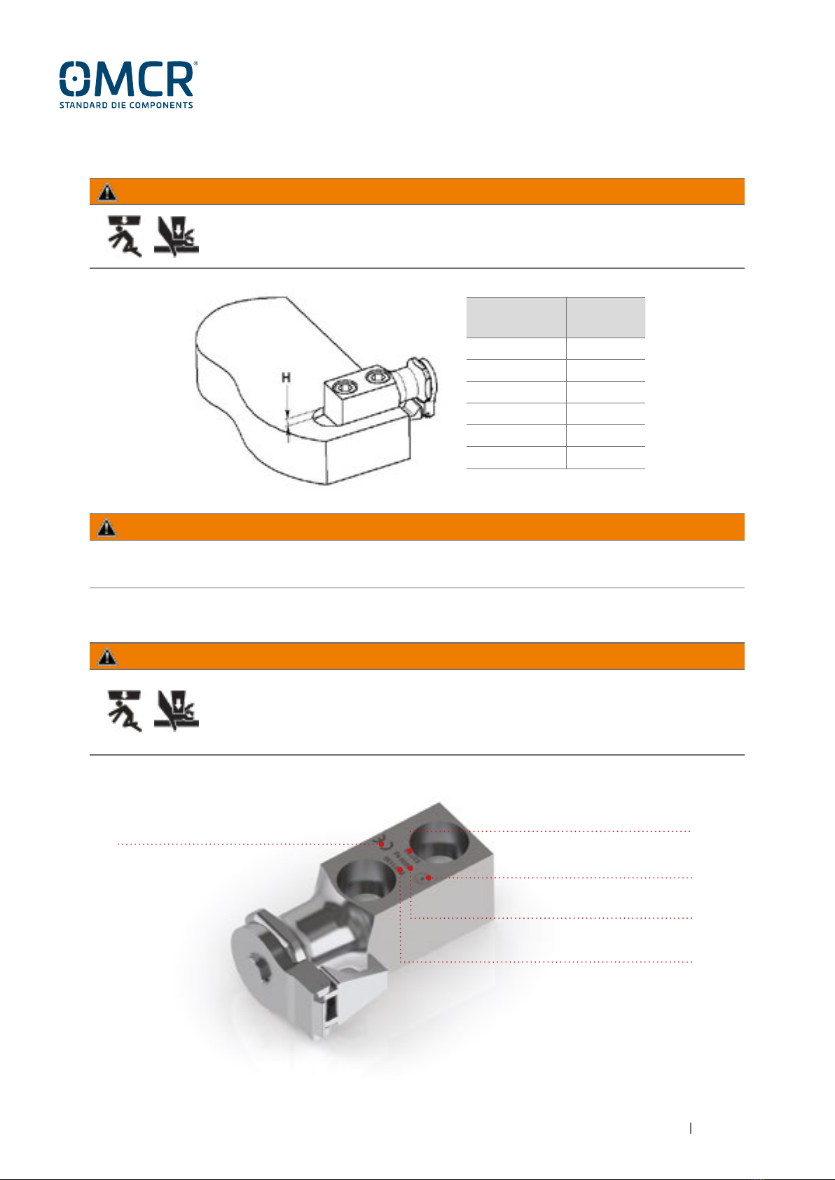
The lifting brackets have to be used as couplets for ropes and they allow users to make on safety the following
actions: LIFTING / HANDLING / OVERTURNING; the material, the production and the quality-check of all
OMCR lifting pins comply with the Directive 2006/42/EC requirements; all OMCR lifting elements have been
tested with a static safety factor even to a minimum 1.5, all materials have been analyzed according to UNI
EN 10204, samples of all materials have been subjected to tensile stress test according to UNI EN 10002.
Calculations and risk assessments have been made according to VDI3366 norms.
An improper or opposed use in reference to the prescriptions treated in this manual, deletes this EC
conformity declaration and relieves OMCR from any responsibility.
WARNING
According to ISO 3864-2, ANSI Z535.6, ANSIZ535.4 norms, in this manual are classified the following safety
messages and symbols:
2. SYMBOLS AND WARNINGS CLASSIFICATION
WARNING
WARNING
NOTE
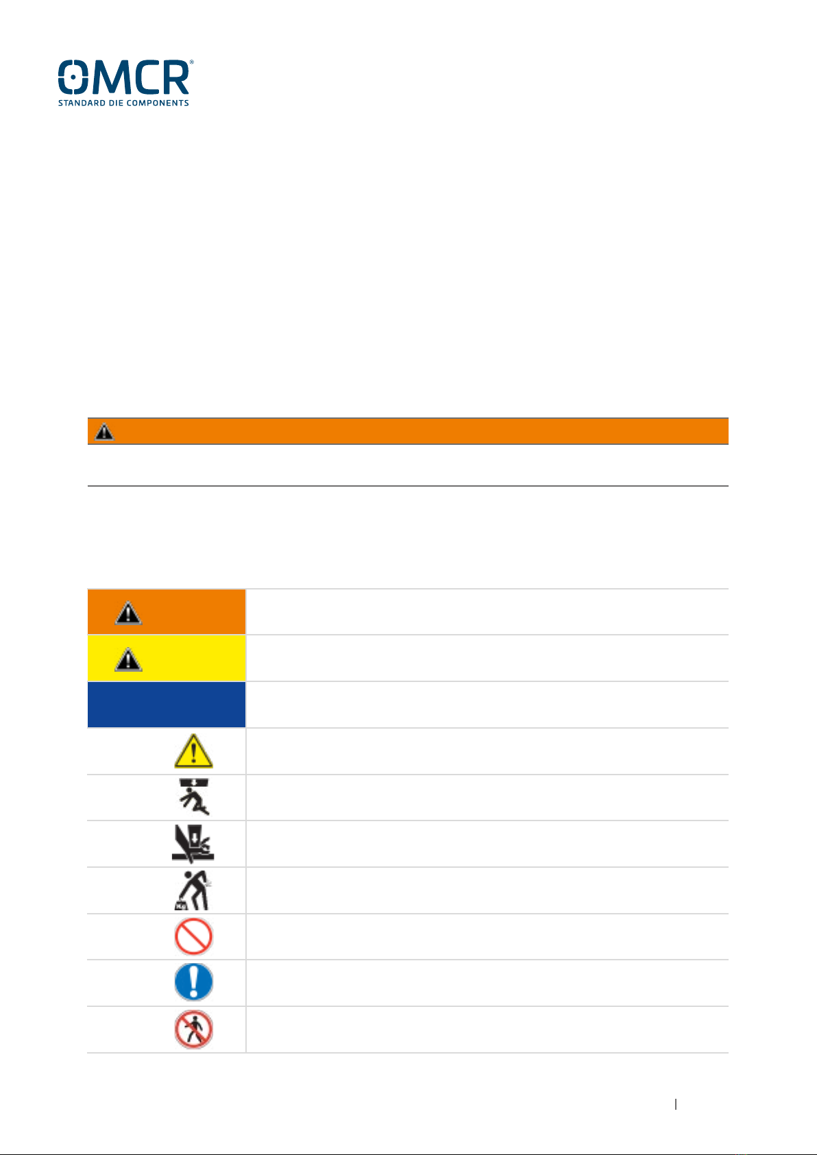
It indicates a hazardous situation which, if not avoided, could result
in death or serious injury.
It indicates a hazardous situation which, if not avoided, could result
in minor or moderate injury.
It indicates advices on use or other especially helpful informations.
It indicates general warning symbol.
It indicates hazard of crushing consequent to an accidental fall or overturning
of the load.
It indicates hazard of crushing.
It indicates musculoskeletal disorders for the handling of the loads.
It indicates forbidden actions or uses.
It indicates mandatory actions to avoid hazards.
It indicates that it is forbidden to stop or to transit.