Omega 90000 Instructions for use

Model 90000
Model Number: 90000
Strut Spring
Compressor
Operating Instructions
& Parts Manual
OIPM# 90000-SSC2
Printed in Taiwan
SFA Companies ©2002
10939 N. Pomona Avenue
Kansas City, MO 64153

2
OIPM#90000-SSC2
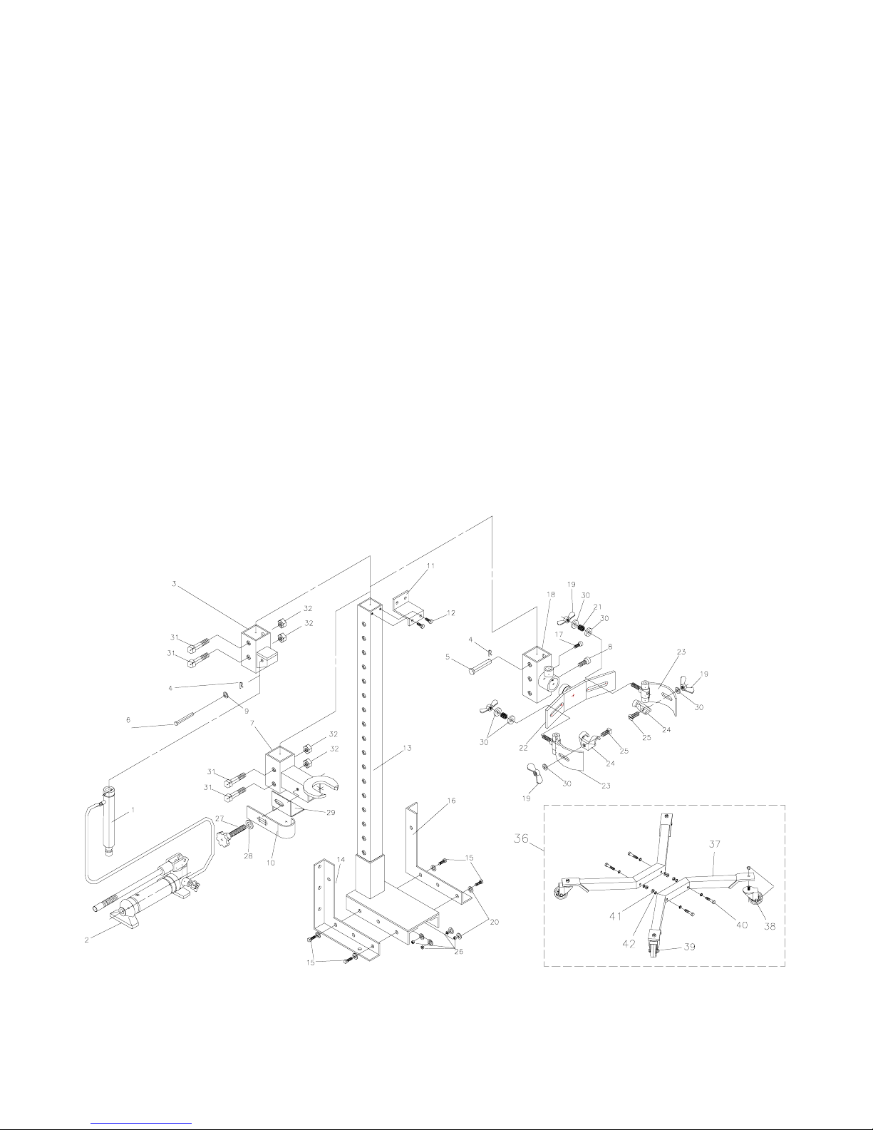
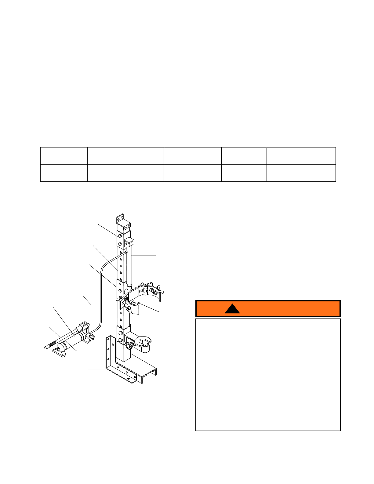
Figure 1 - Model 90000 Nomenclature
BEFORE USE
Note: Never service strut spring compressor while
in use.
1. Familiarize yourself with this tool and the hazards
associated with its improper use.
2. Always refer to and have available a credible service
manual covering the year, make and model of the
vehicle being serviced. Follow manufacturer's
guidelines for strut removal, service and installation
procedures.
3. Inspect before each use. DO NOT USE if bent,
broken, cracked or leaking parts are noted. Repair
or replace with factory authorized components only.
4. No alteration of this device is permitted.
Note: Wall mount is not for use on wooden studs,
sheet rock or similar materials.
Save these instructions. For your safety, read, understand, and follow the information provided with and on this
product. The owner and operator of this equipment shall have an understanding of this jack and safe operating
procedures before attempting to use. The owner and operator shall be aware that use and repair of this product may
require special skills and knowledge. Instructions and safety information shall be conveyed in the operator's native
language before use of this product is authorized. If any doubt exists as to the safe and proper use of this product,
remove from service immediately. Inspect before each use. Do not use if broken, bent, cracked, or damaged parts
(including labels) are noted. Any Spring Compressor that appears damaged in any way, operates abnormally or is
missing parts, shall be removed from service immediately. It is recommended that an annual inspection be done by
qualified personnel. Labels and Operator's Manuals are available from manufacturer (see Replacement Parts, page
6)
PRODUCT DESCRIPTION
Omega Heavy Duty Strut Spring Compressor Model 90000 is designed as an aid in safely replacing strut springs.
SPECIFICATIONS
Product Size ( L X W X H )
90000
Hydraulic Stroke
Model
12 1/4" X 11 7/8" X 52 5/8" 10" (14 ¼ Max. ~ 4 ¼ Min.)
Recommended
Strut Spring Dia.
4" ~ 10" 15 1/2"
Max. Working
Space
ram
hydraulic pump
upright
base
handle
oil filler plug
release valve
ram bracket
strut spring channel
spring clasp
!WARNI N
G
Read and understand all printed materials provided
with and on this device. Ensure workpiece is
compatible with and is securely fastended in
compressor fixture. Only compress spring sufficiently
to remove retaining nut and hardware. Keep feet and
hands from loading area. Never leave loaded spring
compressor unattended. Ensure the user is
thoroughly familiar with the controls and operational
characteristics of this product and is aware of the
potential hazards associated with its use. Always
wear safety glasses when using. Use only on hard
level surfaces. Do not use this device for any purpose
other than that for which it is intended. Failure to
heed these warnings may result in personal injury
and/or property damage.

3OIPM#90000-SSC2
ASSEMBLY (please refer fig. 7 on page 6)
Little, if any, assembly is required of this strut spring
compressor. Familiarize yourself with the illustrations
in the operator's manual. Know your strut spring
compressor and how it operates before attempting to
use.
A. For beam mount
1. Attach Lower Wall Brackets (#14 & #16) to Upright
(#13) using 4 Bolts (#15), 8 Washers (#20) and 4
Nuts (#26). Please refer fig. 2.
2. Insert Ram Piston into Strut Spring Channel (#18)
and tighten using Bolt (#17).
Note: Hardware needed to secure product to wall is
not included.
B. For bench or floor mount
1. Attach Lower Wall Brackets (#14 & #16) to Upright
(#13) using 4 Bolts (#15), 8 Washers (#20) and 4
Nuts (#26), please refer fig. 3 (for bench) or fig. 4
(for floor).
Note: Bench table must be minimum 3/4" thickness if
hardwood or pressboard is used.
2. Insert Ram Piston into Strut Spring Channel (#18)
and tighten using Bolt (#17).
Note: Hardware needed to secure product to beam is
not included.
C. Support leg option
1. Attach each Support Leg (#37) to Upright (#13)
using 4 Bolts (#40), 4 Nuts (#41) and 8 Washers
(#42), please refer fig. 5 & 7.
Note: Do not attach lower wall brackets with support
leg option.
2. Insert Ram Piston into Strut Spring Channel (#18)
and tighten using Bolt (#17).
Note: Before using, apply a light coating of bearing
grease to mid-section of upright.
Fig. 2
connect to base
(1st & 3rd hole)
connect to
wall
left lower
wall bracket
Fig. 3
connect to base
(1st & 3rd hole)
connect to bench
left lower
wall bracket
Fig. 4
connect to base
(2nd & 3rd hole)
left lower
wall bracket
Fig. 5

4
OIPM#90000-SSC2
OPERATING INSTRUCTIONS
Always follow vehicle manufacturers recommendation
for removal and installation
1. Secure base of strut in compressor fixture by
adjustable strut shaft clasp.
2. Secure spring with claw assembly.
3. Pump to compress spring.
4. Install safety bar in upright directly above strut
spring channel (please refer fig. 6 ).
5. Remove nut and retainer cup assembly.
6. Decompress spring and remove.
7. Replace damaged components.
8. Install spring and compress.
9. Install retainer cup assembly and nut.
10. Tighten retainer nut.
11. Remove safety bar from operation step #4 position.
Reposition to near top of upright channel.
12. Decompress spring and remove strut assembly from
fixture.
MAINTENANCE
Lubrication of upright is required in normal service. If
service environment has a history of producing rust, it
may be necessary to coat all exposed surfaces with a
light machine oil. DO NOT allow lubricant to contact
claw assemblies nor strut springs. IF SO, clean and
dry thoroughly before using the spring compressor.
Fig. 6
insert through
upright
safety
bar
strut spring
channel
upright
Symptom Possible Causes Corrective Action
Ram will not extend
Ram bleeds off
Will not extend to full extension
• Release valve not tightly closed
• Overload condition
• Fluid level low
• Fluid level low
• Air trapped in system
• Release valve not tightly closed
• Overload condition
• Hydraulic unit malfunction
• Ensure release valve tightly closed
• Remedy overload condition
• Ensure release valve tightly closed
• Remedy overload condition
• Contact Omega Tech. Service
• Ensure proper fluid level
• With ram fully retracted, remove oil
filler plug to let pressurized air
escape, then reinstall oil filler plug
Poor performance
Ram will not retract after
unloading
• Reservoir overfilled
• Linkages binding
• Drain fluid to proper level
• Clean and lubricate moving parts
TROUBLESHOOTING

5OIPM#90000-SSC2
REPLACEMENT PARTS (See attached exploded drawing on page 6)
Available Parts: Please refer to the Parts drawing when ordering parts. Not all components of the compressor are
replacement items, but are illustrated as a convenient reference of location and position in the assembly sequence.
When ordering parts, give Model number, serial number and description. Call or write for current pricing:
SFA Companies 10939 N. Pomona Ave. Kansas City, MO 64153, U.S.A. Tel:(888)332-6419 Fax:(816)891-6599
ONE YEAR LIMITED WARRANTY
For a period of one (1) year from date of purchase, SFA Companies will repair or replace, at its option,
without charge, any of its products which fails due to a defect in material or workmanship, or which fails to conform
to any implied warranty not excluded hereby.
Performance of any obligation under this warranty may be obtained by returning the warranted product,
freight prepaid, to SFA Companies. Warranty Service Department, 10939 N. Pomona Ave., Kansas City, MO 64153.
Except where such limitations and exclusions are specifically prohibited by applicable law, (1) The
CONSUMER'S SOLE AND EXCLUSIVE REMEDY SHALL BE THE REPAIR OR REPLACEMENT OF DEFECTIVE
PRODUCTS AS DESCRIBED ABOVE, and (2) SFA Companies SHALL NOT BE LIABLE FOR ANY
CONSEQUENTIAL OR INCIDENTAL DAMAGE OR LOSS WHATSOEVER, and (3) THE DURATION OF ANY AND
ALL EXPRESSED AND IMPLIED WARRANTIES, INCLUDING WITHOUT LIMITATION, ANY WARRANTIES OF
MERCHANTABILITY AND FITNESS FOR A PARTICULAR PURPOSE, IS LIMITED TO A PERIOD OF ONE (1)
YEAR FROM DATE OF PURCHASE.
Some states do not allow limitations on how long an implied warranty lasts, so the above limitation may not
apply to you. Some states do not allow the exclusion or limitation of incidental or consequential damages, so the
above limitation or exclusion may not apply to you. This warranty gives you specific legal rights, and you may also
have other rights which vary from state to state.

6
OIPM#90000-SSC2
Figure 7 - Replacement Parts Illustration for Model 90000
Model 90000
Parts No. Description Quantity
1 ram plunger 1
2 hydraulic pump 1
3 ram bracket 1
4 spring clip 2
5 bracket pin D15.8 x 96 1
6 ram position pin D10 x 76 1
7 strut support 1
8 bolt M10 x 1.5 x 10L 1
9 washer D20 x D10.4 x 1.2 1
10 adjustable strut shaft clasp 1
11 wall bracket - upper 1
12 bolt M10 x 1.5 x 16L 2
13 upright 1
14 wall bracket - lower left 1
15 bolt 1/2" - 12UNC x 1 1/4" 4
16 wall bracket - lower right 1
17 bolt - M8 x 1.25P x 15L 1
18 strut spring channel 1
19 wing nut 1/2" - 12 UNC 4
20 washer D24 x D13 x 2.5T 8
21 spring D18 x D2 x D15 2
Parts No. Description Quantity
22 spring clasp bracket 1
23 spring clasp holder 2
24 sping clasp / claw 2
25 screw 1/2" - 12 UNC x 1/2" 2
26 nut W1/2 x 12 UNC 4
27 knob 1
28 washer D31 x D16.2 x 4T 1
29 " L " Bracket 1
30 washer D30 x D13 x 5T 6
31 bolt - M16 x P2 x 90L 4
32 nut - M16 x P2 4
36 leg assy. (for option only) 1
37 support leg 2
38 swivel wheel assy. 2
39 swivel wheel assy. 2
40 bolt 4
41 nut - nylon 4
42 washer 8
43
-- label(s) (not shown) 1
-- manual (OIPM# 90000-SSC2) 1
oil filler plug (not shown) 1

Notes
SFA Companies
10939 N. Pomona Ave. Kansas City, MO 64153, U.S.A.
Tel:(888)332-6419 Fax:(816)891-6599 E-Mail:[email protected] Omega Website: http://www.omegalift.com

Notes
SFA Companies
10939 N. Pomona Ave. Kansas City, MO 64153, U.S.A.
Tel:(888)332-6419 Fax:(816)891-6599 E-Mail:[email protected] Omega Website: http://www.omegalift.com
Table of contents
Other Omega Air Compressor manuals