Omega OAL-100 User manual

OMEGA AUTOMATICS 2020 v3.0.2 1
OAL-100 INSTALLATION INSTRUCTIONS
WARNING!
READ AND FOLLOW ALL INSTALLATION INSTRUCTIONS CAREFULLY!
FAILURE TO DO SO MAY RESULT IN PERSONAL INJURY OR PROPERTY DAMAGE!
AVOID ELECTRICAL SHOCK
DISCONNECT POWER DURING INSTALLATION
PLEASE READ ALL INSTRUCTIONS BEFORE INSTALLATION
POWER SUPPLY REQUIRED 115+/- 5VAC-60 HZ 0.4 AMPS
CONTROL BOARD POWER SUPPLY 16VDC
CONTROL BOARD TO BE GROUNDED
KEEP FINGERS & CLOTHING CLEAR OF ALL MOVING PARTS
ADJUSTMENTS TO BE PERFORMED BY APPROVED TECHNICIAN ONLY
ALTERATION TO ANY COMPONENTS IS PROHIBITED
REMOVE ANY MECHANICAL DEVICES OR LOCKS THAT INTERFERE WITH THE
OPERATION OF THE DOOR, (OTHER THAN PARTS INTEGRATED WITH THE OPERATOR
SYSTEM)
OPERATOR TO BE INSTALLED 8 FEET MINIMUM ABOVE GROUND IF THERE ARE ANY
EXPOSED MOVING PARTS

OMEGA AUTOMATICS 2020 v3.0.2 2
Table of Contents
Installation procedure .............................................................................................................................................4
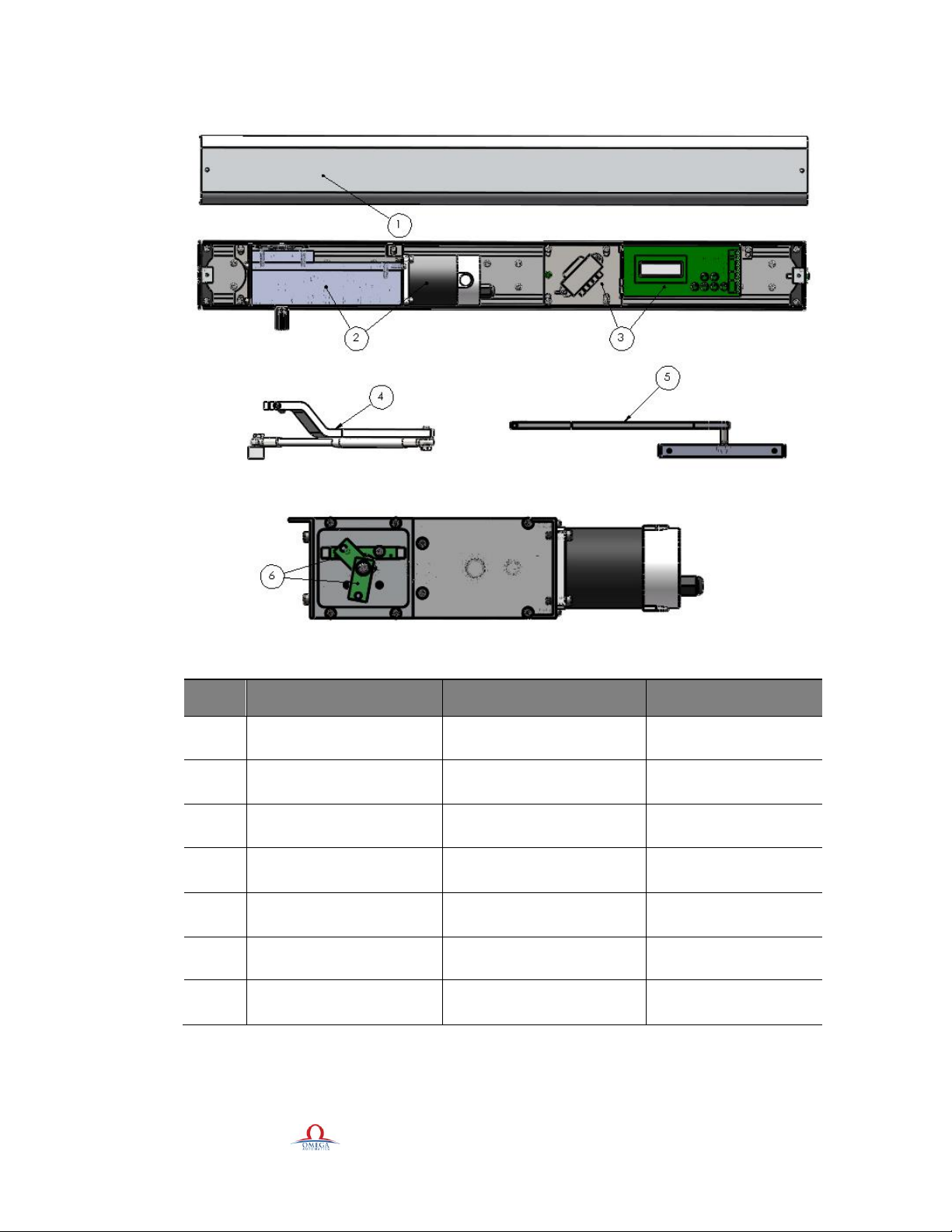
1. Replacement parts ...............................................................................................................................................5
2. General Information............................................................................................................................................6
2.1 Installation Instructions....................................................................................................................................6
2.2 Manual storage.................................................................................................................................................6
2.3 omegaautomatics.com website ........................................................................................................................6
2.4 Dimensions .....................................................................................................................................................6
2.5 Building codes and standards ..........................................................................................................................6
3. Product description..............................................................................................................................................6
3.1 Intended use.....................................................................................................................................................6
3.2 Maximum deck weights...................................................................................................................................6
3.3 Hardware as shipped........................................................................................................................................7
3.3.1 Single swing door ..................................................................................................................................7
3.3.2 Double swing door ................................................................................................................................7
4. Safety information ...............................................................................................................................................7
4.1 Safety Instructions............................................................................................................................................7
4.2 Safety warnings................................................................................................................................................7
4.3 Residual hazard................................................................................................................................................8
5. Recommended tools.............................................................................................................................................8
6. Standard torque ranges.......................................................................................................................................8
7. OAL-100 installation process..............................................................................................................................9
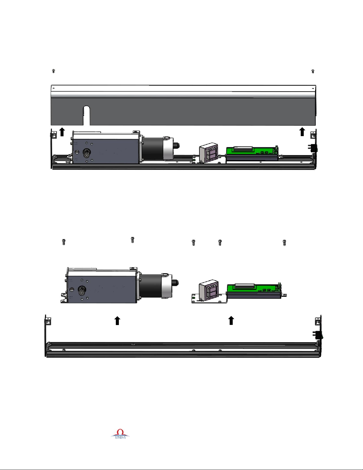
7.1 Unpack the box and take out cover..................................................................................................................9
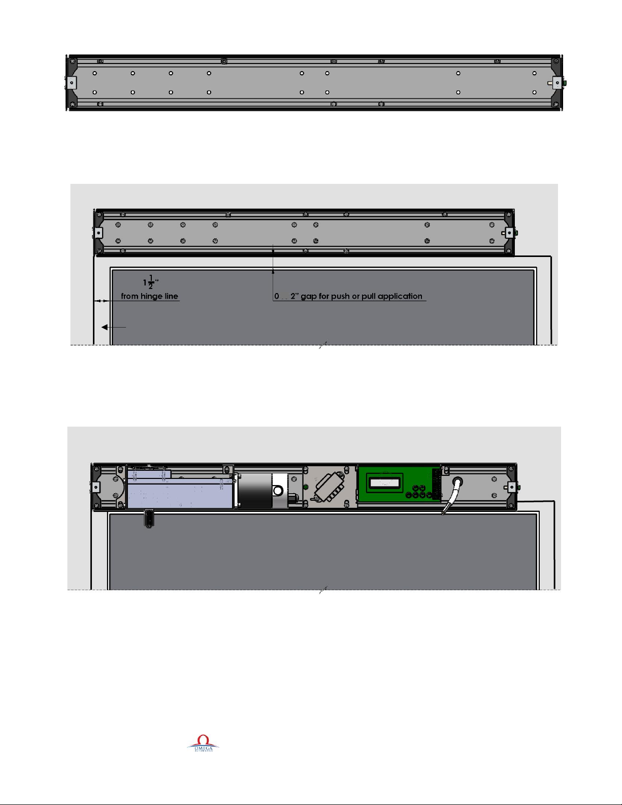
7.2 Installation of bottom track on the wall...........................................................................................................9
7.3 Motor and control board wiring ....................................................................................................................10
7.4 Arm installation ............................................................................................................................................11
7.4.1 Push arm application ............................................................................................................................11
7.4.2 Pull arm application .............................................................................................................................13
7.5 Programming (Basic).....................................................................................................................................14
7.6 Programming Heavy Duty (XP) operators.....................................................................................................18
8. Trouble shooting................................................................................................................................................19

OMEGA AUTOMATICS 2020 v3.0.2 3
9. Universal Washroom Mode...............................................................................................................................20
9.1 Parameters......................................................................................................................................................20
10. Access control mode.........................................................................................................................................20
10.1 Parameters....................................................................................................................................................20
11. Advanced setting..............................................................................................................................................21
12. Terminal description .......................................................................................................................................23
13. Parameter description ....................................................................................................................................23
14. Re-Learn ..........................................................................................................................................................24
15. Changes in software version ...........................................................................................................................24
16. Programming encoder and parameters ........................................................................................................25

OMEGA AUTOMATICS 2020 v3.0.2 4
Installation procedure:
Step 1 •Remove the cover from operator
Step 2 •Mount header on the wall
Step 3
•Push/Pull arm adjustment and
installation
Step 4 •Test the control board
Step 5 •Setup the magnets
Step 6
•Connect the inputs/outputs to the
control board
Step 7 •Programming the system
Step 8 •Close the header
Step 9 •Place the AAADM Sticker

OMEGA AUTOMATICS 2020 v3.0.2 5
1. Replacement parts
Fig 1.1
Item
Category
Description
Part number
1
Swing door operator
OAL-100 cover
OA Ph-001
2
Swing door operator
OAL-100 motor and
gearbox
OA Pm01 & OA Pg01
3
Swing door operator
OAL-100 motor and HD
gearbox
OA Pm01 & OA Pg10
4
Swing door operator
OAL-100 control board
and transformer
OA Pc01
5
Swing door arms
Push arm kit (clear)
OA Pr01
6
Swing door arms
Pull arm kit (clear)
OA Pr02
7
Swing door sensors
OAL-100 sensor set
OA Pg-011

OMEGA AUTOMATICS 2020 v3.0.2 6
2. General Information
2.1 Installation Instructions
This manual provides installation instructions for OAL-100 automatic swing door operators used in Single door and pair
door installations.
2.2 Manual storage
This document must be kept in a secure place, and accessible for reference as required If the door system should be
transferred to another facility ensure that this document is transferred as well.
2.3 omegaautomatics.com website
Manuals are available for review, download, and printing on the omegaautomatics.com website.
2.4 Dimensions
Unless otherwise specified, all dimensions are given in inches (")
2.5 Building codes and standards
OAL-100 installation: observe applicable national and local building codes
3. Product description
3.1 Intended use
The OAL-100 is electromechanical operators used exclusively for opening and closing interior or exterior swing doors.
The OAL-100 operator installed in a surface mount header at customer site. The header must be installed on an interior
building surface. For double swing doors, both operators are installed in a single header.
❖To reduce risk of injury to persons, use this OAL-100 operator only with automatic Swing doors that the operator
is designed for Reference Chapter 6, Technical data.
3.2 Maximum door weight
OAL-100: 250 pounds (113.398 kg) at 48" door width.
*Based on prevailing conditions at the door opening.

OMEGA AUTOMATICS 2020 v3.0.2 7
3.3 Hardware as shipped
3.3.1 Single swing door
1. Box containing surface mount header assembly for one OAL-100 operator. Included inside header:
Surface Mount
OHC (Over Head Concealed)
In Ground
Motor Gearbox
Motor Gearbox (Spline/ Square
spindle)
Motor Gearbox
Control Board
Control Board
Control Board
Arm Assembly Kit
Center Spindle Arm Assembly Kit
Square Spindle Jockey Box
Center Hung Top Arm
Bottom Arm
3.3.2 Double swing door
1. Box containing surface mount header assembly for two OAL-100 operators. Included inside header:
Manual and Auto (Surface
Mount)
Manual and Auto (OHC or In
Ground)
Double Auto
1 Motor Gearbox
Motor Gearbox (Spline/ Square
Spindle)
2 Motor Gearboxes
1 Control Board
Manual Door Closer Dorma RTS 88
2 Control Boards
2 Arm Assembly Kits
Center Spindle Arm Assembly Kit
or Center Hung Top Arm
2 Arm Assembly Kit (depends on
the type of the operator)
Mount Plate for Manual Door
Closer (LCN4040)
In Ground Bottom Arm
4. Safety information
4.1 Safety Instructions
This document contains important instructions for installation of the OAL-100 swing door operators. Renew these
instructions thoroughly prior to installation and follow them carefully during installation commissioning, troubleshooting
and maintenance.
4.2 Safety warnings
❖Damage to equipment or incorrect equipment operation may result from an incorrect installation.
❖Hazard to mechanical processes by use of control settings elements or procedures not documented in this manual!
❖Electric shock hazard!
❖By use of control elements, settings of Procedures not documented in this manual!
❖Work on electrical equipment and 115 VAC wiring installation must be performed only by qualified personnel!
❖Metallic doors must be grounded per national and local codes!

OMEGA AUTOMATICS 2020 v3.0.2 8
❖Hand pinch point and crushing hazards of door closing edges!
❖Crushing hazards at door closing edges!
4.3 Residual hazard
❖After installation, hazards such as minor crushing, impact with limited force, and risk to unsupervised children
may exist depending on structural design of door area, type of door, and any safeguards that have been
implemented.
❖Hand pinch point and crushing hazards at arm and track!
5. Recommended tools
1- 1/8 Allen key
2- 1/4 Allen key
3- 3/16 Allen key
4- 5/64 Allen key
5- 0.3 mm Flat screwdriver
6- 9/16 Wrench
7- Ph3 Screwdriver
8- Drill/ Drill bits
9- Torque wrench
10- Appropriate screws for application
11- Pressure gauge (0-35 lbf)
Fig 5.1
6. Standard torque ranges
Fastener size
ft lb
M5- #10
3.7
M6- 1/4
7
M8- 5/16
17
M10- 3/8
34
M12- 1/2
58

OMEGA AUTOMATICS 2020 v3.0.2 9
7. OAL-100 installation process
7.1 Unpack the box and take out cover
✓Use 1/8" allen key to take out cover screws
Fig 7.1.1
7.2 Installation of bottom track on the wall
✓Mark the location of the motor on back plate
✓Use 1/4" allen key to take out gearbox fasteners and remove gearbox
✓Use 1/4" allen key to take out controller fasteners and remove controller
Fig 7.2.1
✓Use drill with drill bit that matches screw size to drill for mounting screws.
✓Always drill between channels
✓Drill at least 6 holes on gearbox side and 4 on controller side

OMEGA AUTOMATICS 2020 v3.0.2 10
Fig 7.2.2
✓For push application mount the unit bottom flush with the bottom of the frame
✓For pull application mount the bottom of the unit on top of the frame (2" above the top of the door).
Fig 7.2.3
✓Install the gearbox aligned with marks using appropriate fasteners.
✓Install control board on back plate using appropriate fasteners.
Fig 7.2.4
7.3 Motor and control board wiring
✓Connect motor wire to motor connector on controller.
✓Connect limit switch wire to limit connector on controller.
Door frame
or

OMEGA AUTOMATICS 2020 v3.0.2 11
Fig 7.3.1
7.4 Arm installation
7.4.1 Push arm application
✓To install arm on door operator the unit should have 110 VAC power.
✓Add jumper wire on terminals COM and ACT 2
Fig 7.4.1.1
✓Turn the unit on and allow it load the gearbox all the way to hard stop.
✓If the power is not provided, use the arm to manually load the gearbox to hard stop by turning it until hard stop is
reached. Lock the gearbox with metal rod through one of the 1/2” diameter holes at bottom of the gearbox.

OMEGA AUTOMATICS 2020 v3.0.2 12
Fig 7.4.1.2
Fig 7.4.1.3
✓Set the door to stay open at desired angle.
✓Attach arm to spindle approx. 45° on door frame. Fasten 3/16 socket screw on arm
✓Level the rod and attach the block on the arm to the door.

OMEGA AUTOMATICS 2020 v3.0.2 13
Fig 7.4.1.4
Fig 7.4.1.5
✓Push the door slightly to release the locked rod from gearbox, if loaded using power then remove jumper wire
from terminals com and ACT 2.
✓The door should work as it has a manual closer.
✓Attach the PH3 screw with safety washer on bottom of spindle.
✓Door operator is now installed and ready for programming.
7.4.2 Pull arm application
First of all, the operator needs to reach the hard stop itself (by adding a jumper wire like Fig 7.4.1.1) or manually with the
pull arm. In the next step push the rod into gearbox (same as Fig 7.4.1.4) to stop it, then open the door to your desired
fully open position and attach the pull arm to the spindle (Fig 7.4.2.1). In the last step, take out the rod and release the arm
to reach the fully close position.

OMEGA AUTOMATICS 2020 v3.0.2 14
Fig 7.4.2.1
Now, you can follow the below process:
✓Keep the door close
✓Install the track on top of the door same as the following dimensions
Fig 7.4.2.2
✓Slide the roller into the track and push the arm through the spindle then tight the screw with washer at the middle
of spindle
Fig 7.4.2.3
7.5 Programming (Basic)
✓Setting door position switches.
✓Refer to image how the top magnetic switches on gearbox should be set up

OMEGA AUTOMATICS 2020 v3.0.2 15
Fig 7.5.1

OMEGA AUTOMATICS 2020 v3.0.2 16
✓Before accessing menu door needs to be fully closed and door operator control display should say door closed
Fig 7.5.2
✓Press menu touch button
Fig 7.5.3
✓Press SEL touch button to access parameters.
Fig 7.5.4
Door closed
Door closed
Main Menu

OMEGA AUTOMATICS 2020 v3.0.2 17
✓Refer to table for setting parameters.
Parameter
7’-8’ door
8’-10’
10’+
Overload
55-65
65-85
HD
Act Delay
0-2
0-2
HD
Backcheck speed
20-22
20-24
HD
Holding time
˃5
˃5
HD
Opening speed
50-55
50-55
HD
Closing speed
35-50
35-50
HD
Latch speed
1-5
1-5
HD
Hold open
0-OFF 1-ON
0-OFF 1-ON
HD
Power assist
0-OFF 1-ON
0-OFF 1-ON
/
Reactivate
0-OFF 1-ON
0-OFF 1-ON
/
✓Once parameters are set the door operator is ready for learning cycle.
✓Check the doorway for any obstacles and make sure that the door close and open smoothly.
✓Check if the door is fully closed and display shows door closed press the ACT touch button.
Fig 7.5.5
✓The display will show “door opening”.
Door closed

OMEGA AUTOMATICS 2020 v3.0.2 18
Fig 7.5.6
✓The learning cycle does not register obstruction. Make sure that the path of the door is clear from obstacles.
✓Once the learning cycle is completed and the door is in closed position the door operator is programmed.
✓Connect activating device and run multiple test cycle to assure proper operation.
7.6 Programming Heavy Duty (XP) operators
✓After you follow the abovementioned steps of installation of the push or pull arm application, turn on the operator
then control board should recognize the encoder.
✓Press MENU touch button then press down touch button to see “Calibrate”.
Fig 7.6.1
✓Then press the SEL touch button.
✓Screen shows “Hit ACT to begin”.
✓Press ACT button and manually push the door to the maximum opening position.
Door Opening
[Learning]
Calibrate

OMEGA AUTOMATICS 2020 v3.0.2 19
Fig 7.6.2
✓Then release the door to close on its own.
✓The value on the screen should be around 100 ±8.
✓Press SEL button to save the settings.
You can activate the door and scroll through parameters to make adjustments as needed to Backcheck Speed, Overload,
Holding Time etc. as needed for your installation.
You can access to our YouTube channel to watch the sample installation videos with the following link.
https://www.youtube.com/channel/UCI2d_nzMlxHzSmhMQY_e3Fg/featured
8. Trouble shooting
Possible problems
Possible solutions
Door does not open
-Check the power
-Check the ON/OFF switch
-Check the activation devices connection
-Check the display message
Display does not indicate door closed
-Check magnet position
-Check sensor wire
Display does not indicate door open
-Check magnet position
-Check sensor wire
Door stops opening halfway
-Adjust overload setting
Door does not close
-Check for rubbing on floor and ceilings
-Check the magnets and sensor wire
-Check if the gearbox has tension
Electric strike does not release
-Check wiring
-Check hardware
-Check strike connection
-Check strike voltage
Touch buttons do not respond
-Clean fingers or wipe the touch buttons
Hit ACT to begin

OMEGA AUTOMATICS 2020 v3.0.2 20
9. Universal Washroom Mode
•Normally is unlocked
•Install the door operator for required application based on installation instructions
•Adjust parameters for basic setup
•Follow the universal washroom wiring diagram to connect all the devices to proper terminals
•Once the devices are wired and door operator is programmed for basic setup, access the advanced settings to
change operating mode of the controller
9.1 Parameters
Latch time: Change from 2 to 0
Control mode: Change from 1 to 2
Once the door is closed the display will say door closed (unoccupied)
Fig 9.1.1
10. Access control mode
1. Install the door operator following instructions
2. Adjust parameters for basic setup
3. Follow to access control wiring diagram
4. Signal from access control panel needs to be dry to connect device and signal from access control panel to proper
terminals.
5. Once devices are wired and the door operator is programmed for basic setup, access advanced settings to change
operating mode of controller.
10.1 Parameters
✓Control mode: Change from 1 to 3
Door Closed
[Unoccupied]
Other manuals for OAL-100
1
Table of contents
Other Omega Door Opening System manuals
Popular Door Opening System manuals by other brands

Solido
Solido Eco manual

Brookfield
Brookfield NB-4120-2-DC user manual

CornellCookson
CornellCookson SGH 50023E Installation instructions and operation manual

Dorma
Dorma AGILE 150 Installation instruction, care instructions, service and maintenance

GU
GU OTS 735 Assembly instructions

Dorma
Dorma 8600 IS manual