Omegawave OMEGAZONE STD User manual

210621
Laser Speckle Blood Flow Imager
OMEGAZONE
STD
USER’S MANUAL
( LSI : ver 6.1, LIA : ver 6.0)

1
TABLE OF CONTENTS
Page
■ CAUTION 2
■ SUMMARY 3
■ HARDWARE 4
1. Parts name and the function
2. Setup of the stand
4. Lens adjustment
5. Polarization adjustment
6. Block diagram
■ LSI software 14
1. Controls and display
2. Project Configuration File
3. LSI Front Panel
4. LSI operation
■ LIA software 26
1. Controls and display
2. Analysis Configuration File
4. LIA Front Panel
5. LIA operation
■ Handling in use 40
■ Appendix 42
1. Lens, WD and measurement area(Working Distance)
2. Time for saving data and capacity
3. User name and organization change
4. License certification of OS
■ Specification 44
■ Warranty 46

2
CAUTION
1. Do not turn on the power switch of the power supply for the laser
unit and CMOS camera before connecting the cables of the laser unit
and the CMOS camera.
2. Check if there is enough capacity in the HDD for storing data
before measuring. Data cannot be stored if there is not enough
capacity.
3. Do not touch the lens, the optical filter and the CMOS camera by
bare hands.
4. Do not see the laser light through a lens or an optical instrument.
5. Do not update Windows and the other software automatically or
manually.
The function may interrupt the software of this instrument.
6. The function of FireWall is set as “OFF” because the interface of
the CMOS camera is Ethernet. Do not change the status.
7. Do not use this instrument as a conventional computer.
______________
This manual is changed without a preliminary notice.
There is a copyright of this manual in OMEGAWAVE, INC.
A reproduction without permission is prohibited in any kind of form.
Microsoft and Windows are registered trademarks of Microsoft Corporation.
Intel, Core i5 and Core i7 are registered trademarks of Intel Corporation.
OMEGAWAVE, INC. has the copyright of LSI and LIA software.

3
SUMMARY
The laser speckle blood flow imager, OMEGAZONE STD, is the instrument to
obtain the colored blood flow image of living tissue non-invasively and
continuously.
OMEGAZONE STD shows more than 2 images/sec with high resolution
(639-480), or 15 images/sec with low resolution (212 - 160).
Every point is captured by the pixel of the CMOS camera simultaneously,
therefore, there is no time lug between the all points and the each blood flow
value can be compared.
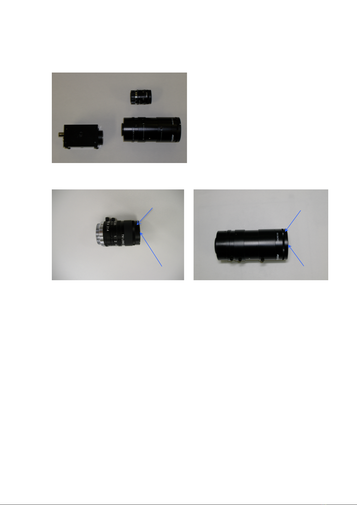
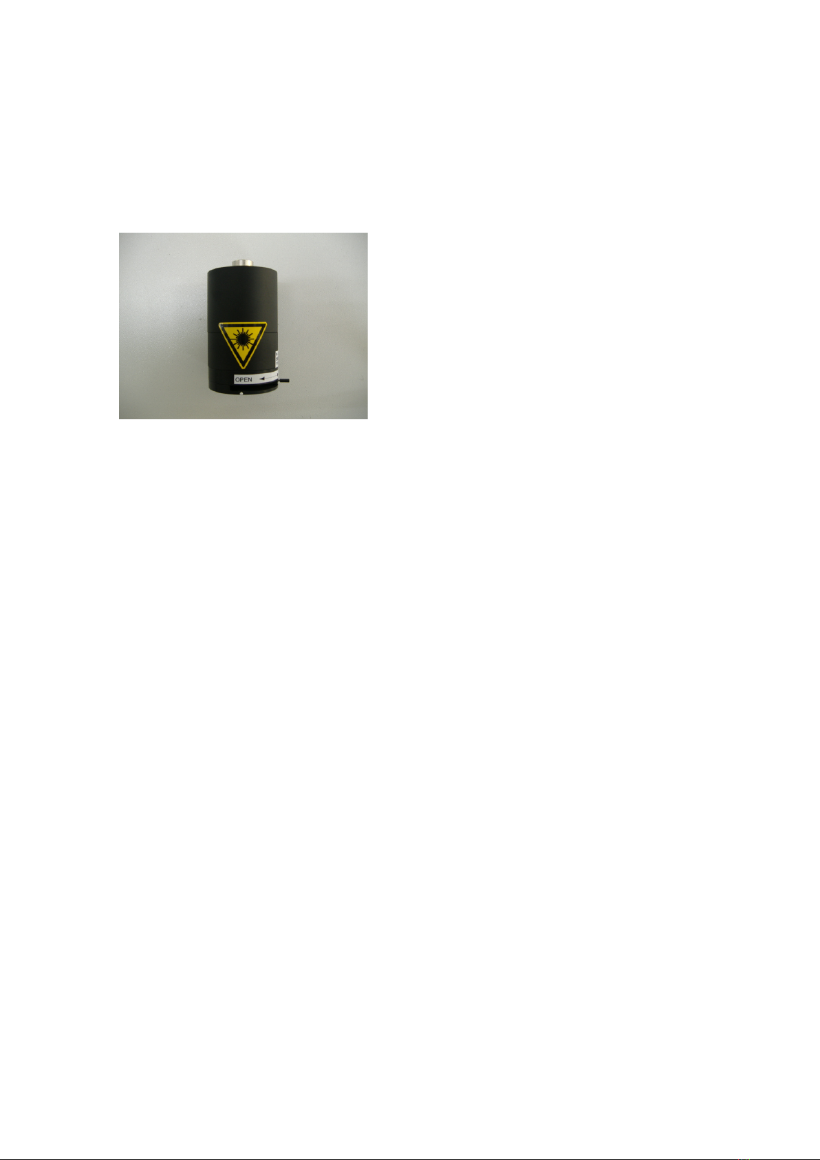
This OMEGAZONE STD consists of the laser unit, the CMOS camera, the lens
+ hybrid filter, the computer-based image processor and the stand.
The lens can be changed to adapt the measurement size. The measurement
size is about from 1 cm x 1 cm to 40 cm x 40 cm, and it is suitable for cerebral
blood flow measurement and limb blood flow measurement for small animals,
and for human.
OMEGAZONE STD includes two kinds of software. One is for measurement,
LSI, and the other is for analysis, LIA. Separating the software makes the
operation easier.
This instrument was developed based on the study of Dr. Kevin Forrester in
University of Calgary.

4
6. USB key
HARDWARE
1. Parts name and the function
1) Computer-based imager processor
This computer-based imager processor shows black/white real images by laser
light and tissue blood flow images calculated by the installed software. The
images captured by the CMOS camera are processed to obtain the blood flow
images. The operating system (the OS) is Windows 10.
The hard disk drive of this computer-based image processor is assigned to two
regions, C and E. The OS, the blood flow software and other application
software are installed in the C drive. The E drive is for data. Initial setting assigns
the E drive for saving.
Turn the power switch (I) on the keyboard after all cables were connected.
1. Computer-based
Image Processor
4. Laser Unit
3. CMOS camera
+ Lens
2. Power supply
5. Arm Stand
6. USB key

5
2) Power supply
The power supply contains the laser drive circuit, the power supply for the
CMOS camera and the intermediate connector for the CMOS camera.
Turn on the laser switch after the laser unit and the CMOS camera were
connected. Connection after the power being ON may destroy the laser diodes.
Front Rear
The main power switch is the key switch. Turn it to the clockwise direction for
the power ON. When the key is on the OFF side, the key can be removed.
The Laser SW is for ON/OFF of the laser light. The Red laser SW is for
ON/OFF of the red pointer laser light. The red laser light does not affect the
blood flow value.
Connect the 12-pin cable between the Laser unit and the Connector for laser
unit. Connect the 12-pin cable between the CMOS camera and the Connector
for CMOS camera, too.
The GigE connectors have IN and OUT. Connect one GigE cable from the
CMOS camera to the IN, and connect the other cable from the OUT to the
computer-based image processor. The IN and OUT is connected inside the
power supply, and the CMOS camera is not damaged by misconnection.
Red laser SW
Connector for
laser unit
GigE connectors for CMOS
camera and the computer
Connector for CMOS camera
Power connector
Laser SW
Main power SW

6
3) CMOS camera and Lens
The images are captured with the CMOS
camera.
The hybrid filter is attached on the lens.
This is the specialized filter combined of the
polarizer and the color filter not to detect the
direct reflection from tissue surface and the
light from outside.
The filter has the direction of polarization,
and it is shown as the white dot.
Make the white dot showing the same
direction of the dot of the laser unit.
Mono-focal Lens
Zoom Lens
The measuring area matrix of the W.D. and the lens is shown in Appendix.
Zoom Lens
Mono-focal Lens
CMOS camera
・
Hybrid filter
Hybrid filter
・
・
White dot
White dot

7
4) Laser unit
The laser diodes for measurement (infrared, 780 nm) and the positioning (red,
650 nm) are installed in the laser unit. The left side is the laser for measurement.
The positioning laser can be turned off with the RL switch on the rear panel
when it is not needed.
The laser diodes have polarization,
and the direction is marked by the
white dot on the laser unit.
Turn the hybrid filter attached to the
lens to make the white dot show the
same direction as the white dot on the
laser unit.
※ Shut the shutter when the
measurement is over to not to
collect dust on the lens inside.
5) Arm stand
The arm stand holds the CMOS camera, the lens and the laser unit.
Adjust the working distance (WD), distance between the lens and the tissue
under study, according to the size of the tissue.
Spread the black sponge sheet under the animal to obtain clear blood flow
images when the tissue does not occupy the display. The black sheet does not
reflect the laser light, and the effect makes the blood flow images clear.
6) USB key
This key allows the blood flow imager software, LSI and LIA, to work.
Insert and pull out the USB key when the power of the computer-based image
processor is off.
White dot
Shutter
knob

8
2. Set up of the arm stand
The arm stand is composed of the base, the cramp, the pole and the arm.
(1) Install the cramp on the table
used for measurement.
(2) Stand the pole on the cramp
by the screws.
(3) Install the arm on the pole.
Screws
Arm

9
The hold plate with the CMOS
camera.
(4) Install the hold plate with the
CMOS camera on the arm stand by
the four screws.
(5) Attach the lens on the CMOS
camera.
Lens

10
(6) Install the laser unit on the hold
plate by the screw knob.
(7) Connect the CMOS and the laser
unit to the power supply by the 12 pin
cables.
(8)The CMOS camera has two inputs.
One is for the 12-pin cable for the power
supply, and the other is for the Ethernet
cable for the signal.
(9) When the power of Power Supply is
ON by the key switch,
「POWER/TRIG」lamp shows orange
color.
After 30 to 60 second it shows green,
and the measurement can be started.
専用ネジ
For the 6-pin power cable
For the GigE
Ethernet cable

11
3. Wiring
1) Connection to the Computer-based image processor
(1) Connect the AC power cable to the inlet on the left side.
(2) Connect the Ethernet cable from the camera through the power supply to the
Ethernet connector on the right side.
(3) Connect the USB key to the USB connector on the left side.
(4) Connect the mouse to the USB connector on the right side if needed.
Ethernet cable
USB key
AC power cable

12
4. Adjustment of Lens
The mono-focal lenses have the iris and the focus adjustment function.
The zoom lenses have the function of zooming and the focus adjustment
function.
(1) Decide the measurement area, and set the WD (working distance).
(2) Set the iris to “ 5.6 “ for the zoom lens, ZM10-18, for the standard
measurement.
(3) Set the iris to “ 4 “ for the zoom lens, ZM6-8, for the standard measurement.
(4) Adjust the focus to get clear image.
The iris number may different for the different lens.
5. Adjustment of polarization
The laser light has its polarization. It is needed not to detect the surface
reflection from tissue to obtain good blood flow images. To make this setting, the
reflector can be used.
Turn and adjust the ring of the polarizer on the lens to show the reflector
becoming darkest.
Mono-focal
lens
Zoom lens
Iris number should be on the white
dot.
Focus
Reflector

13
OMEGAWAVE, INC.
SWRegulator
650nmLaser
drivecircuit
Computer-based
imageprocessor
CMOScamera
Lens
Hybrid
Filter
Laserunit
Free
780nmLaser
drivecircuit
12V
12pCable
12PConnector
AC100-220V ACAdaptor
650nm
Laserdiode
780nm
Laserdiode
Inlet
12PConnector
Lens
Shutter
AC100-220V
GigE
OZ-2BlockdiagramforCMOS
GigEConnector
Lens
6. Block diagram

14
LSI Software
(LSI ver. 6.1)
1. Summary
The LSI software is for measuring and saving blood flow images.
This software consists of two views.
■Project Configuration File
■LSI Front Panel
2. Project Configuration File
The display is shown after the LSI is opened.
1) Working Directory and File name
The display shows the directory where images will be stored.
The file name is the name that will be the prefix for all image files to be saved.
During the image capture process, the program saves image files under names
composed of the file name, the blood flow mode, the image type and the image
number representing its order in the captured sequence.
For example, the folder name of “ Test “ is made in the volume E in the hard
disk drive. There is one hard disk drive in the computer-based image processor,
but it is separated and assigned as the C and E.

15
2) File Name
Open this “ Test “ folder and enter the file name for the image data being saved.
Without assigning a specific name, “Image” will be the file name automatically.
Do not use “BF” for the original file name because it is recognized as the “Blood
Flow Image” file.

16
Actual fine name is created as” Image HR BF R3T~3500No001”.
HR : Mode
BF : Type of image
R3 : Round
T~3500 : Time
No001 : Number o the image
The specific file name that a user can assign is the place for “Image”. Do not
change the name after the specific name. The software cannot recognize as the
sequence data images when the file name after the specific name are changed.
When the file specific names have to be changed, change the all specific
names of the sequence data images.
Click “OK”, and the Project Configuration File is displayed.
3) Information
A description of the measurement can be entered in this box.
4) Date and Time
The system date and time is shown here.
5) Total Disk Size
Displays, in bytes, the total size of the disk containing the working directory.
6) Free Disk Space
Displays, in bytes, the free space remaining on the disk containing the working
directory. (When the total free disk space is below 30 Mega-bytes the user is
warned.

17
7) Used Disk Space
Displays, in bytes, the used space of the disk containing the working directory.
8) Measurement
Push the “ OK “ button to go to the “ LSI Front Pane l” or the “ Cancel ” button to
exit the LSI program.

18
18
15
6
5
8
12
11
3. LSI Front Pan
LSI Front Panel
Base display
Example of measurement
4
2
7
13
10
14
17
16
19
9
3
1

19
1) Video Controls
These are controls to display real and real-time images of blood flow images.
Click “ Real Video “ switch to show the images. Click again to stop showing the
images.
In the Real Video mode, only real images are displayed at 60 frames per
second.
In the Real Video mode, the user can refer to the Real Image Display window to
focus and adjust the camera lens, and to align the tissue and appropriate region
of interest. The gain of the brightness can be adjusted by using the slide bar
controller next to the display. The brightness is adjusted automatically by
“AUTO“ mode, and is adjusted manually by “ MANUAL “ mode. When the
brightness is saturated, the controller shows the red signal. Lower the gain not to
show the red signal. When the real images show suitable brightness, click “ BF
Video “ to show the blood flow images.
In the BF Video mode, the blood flow images and real images are displayed
simultaneously. The blood flow video rate depends on the blood flow mode.
The user can set up blood flow analysis region in the Blood Flow Image Display
window using the Tool Palette and observing the Mean Blood Flow Plot, Blood
Flow Histogram and Mean Blood Flow Value outputs as they are displayed in
real-time.
The color variation is assigned by the color bar next to the Blood Flow Image
Display. There are two kinds of color bars. One is Standard, and the other is
Enhanced. Choose the proper one for the blood flow images. The color bar can
be selected from the Color Bar in the Tool on the Top menu.
2) Blood Flow Mode
There are three measurement modes in LSI.
(1) Hi-Res : High Resolution
This mode provides blood flow images with the highest resolution. It is done
by capturing a sequence of 20 real images and later analyzing the speckle
fluctuations at each pixel in the sequence of 20 images.
Resolution : 639 - 480
Name of the saved file : HRBF No
Maximum display speed : about 0.7 sec / image
(2) Hi-Speed : High Speed
This mode provides blood flow image capture with the highest speed. It
analyzes the spatial fluctuations of speckle in a single real image.
Resolution : 212 - 160
Name of the saved file : HSBF No
Maximum display speed : about 0.07 sec / image
Table of contents
Popular Laboratory Equipment manuals by other brands

PerkinElmer
PerkinElmer SPECTRUM TWO N user guide

Heidolph
Heidolph MR Hei-Standard instruction manual

Nippon Genetics
Nippon Genetics FastGene FAS Digi Installation instruction

THORLABS
THORLABS S4FC Series user guide

BIOAIR
BIOAIR SafeMate Eco + ABC operating manual

Heidolph
Heidolph Hei-MIX Unimax 2010 operating instructions