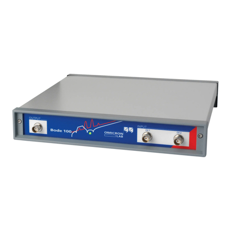
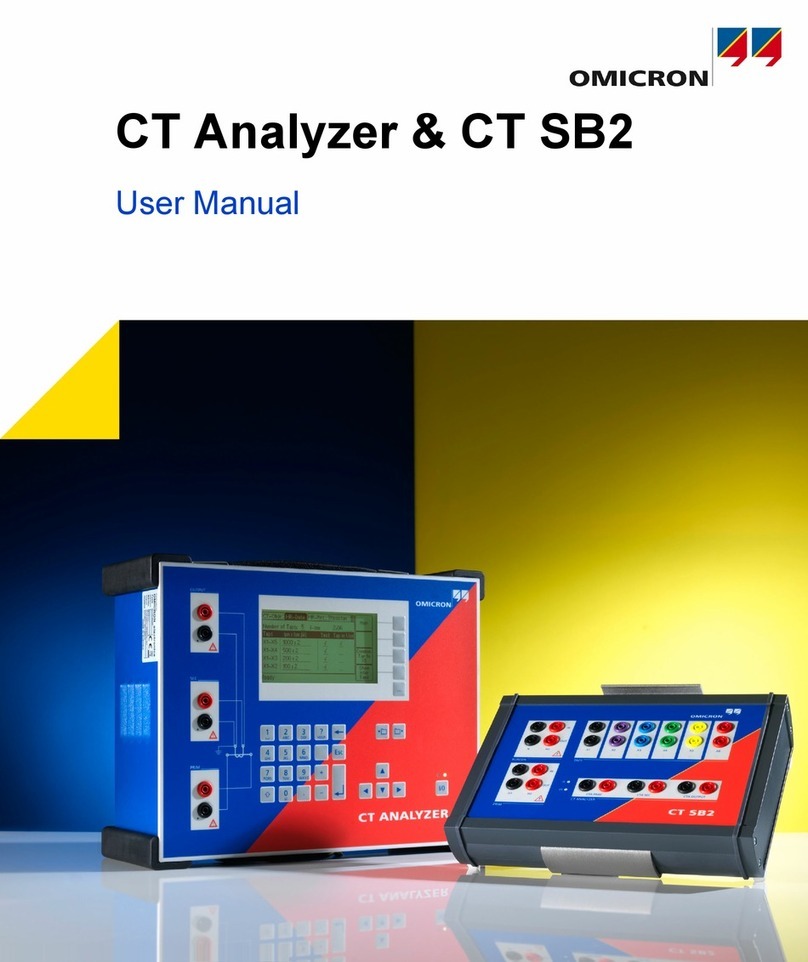
Omicron Lab Bode 100 User manual

Smart Measurement Solutions®
Bode 100
User Manual

Version: ENU1006 05 02 — Year: 2017
© OMICRON Lab, OMICRON electronics. All rights reserved.
This manual is a publication of OMICRON electronics.
All rights including translation reserved. Reproduction of any kind, e.g., photocopying, microfilming,
optical character recognition and/or storage in electronic data processing systems, requires the explicit
consent of OMICRON electronics. Reprinting, wholly or in part, is not permitted.
The product information, specifications, and technical data embodied in this manual represent the
technical status at the time of writing and are subject to change without prior notice.
Windows is a registered trademark of Microsoft Corporation. OMICRON Lab and Smart Measurement
Solutions are registered trademarks of OMICRON electronics.
2OMICRON Lab

Contents
1 Safety instructions 5
1.1 Operator qualifications ................................................................................................................ 5
1.2 Rules for use ............................................................................................................................... 6
1.3 Designated use ........................................................................................................................... 6
1.4 Disclaimer ................................................................................................................................... 6
1.5 Cleaning ...................................................................................................................................... 6
2 Compliance statements and recycling 7
2.1 Compliance statement ................................................................................................................ 7
2.2 Information for disposal and recycling ......................................................................................... 7
3 Bode 100 and accessories 8
3.1 Delivered items ........................................................................................................................... 8
3.2 Optional accessories ................................................................................................................... 9
4 Technical data 10
4.1 Absolute maximum ratings .......................................................................................................... 10
4.2 Bode 100 specifications .............................................................................................................. 11
4.3 Power requirements .................................................................................................................... 12
4.4 System requirements .................................................................................................................. 12
4.5 Environmental requirements ....................................................................................................... 13
4.6 Mechanical data .......................................................................................................................... 13
5 Device overview 14
5.1 Connectors .................................................................................................................................. 14
5.2 Block diagram ............................................................................................................................. 16
5.3 Functional description ................................................................................................................. 17
5.4 Hardware revisions ..................................................................................................................... 17
6 Bode Analyzer Suite introduction 18
6.1 Start screen ................................................................................................................................. 18
6.2 Main window ............................................................................................................................... 19
6.2.1 Measurement configuration .......................................................................................... 21
6.2.2 Trace configuration ....................................................................................................... 23
6.2.3 Ribbon controls ............................................................................................................. 25
6.2.4 Status bar ..................................................................................................................... 27
6.3 Chart context menu ..................................................................................................................... 28
6.4 Options menu .............................................................................................................................. 29
6.5 Hardware setup ........................................................................................................................... 32
7 Measurement types and applications 34
7.1 Gain measurement introduction .................................................................................................. 35
7.2 Impedance measurement introduction ........................................................................................ 37
7.3 Vector Network Analysis ............................................................................................................ 41
7.3.1 Transmission / Reflection ............................................................................................ 41
7.3.2 Gain / Phase ................................................................................................................. 47
7.3.3 Reflection with external coupler .................................................................................... 48
7.4 Impedance analysis ................................................................................................................... 49
7.4.1 One-Port ....................................................................................................................... 49
7.4.2 Impedance Adapter ...................................................................................................... 59
7.4.3 Shunt-Thru .................................................................................................................... 64
7.4.4 Shunt-Thru with series resistance ............................................................................... 65
7.4.5 Series-Thru ................................................................................................................... 66
7.4.6 Voltage/Current ............................................................................................................. 67
Contents
OMICRON Lab 3

7.4.7 External Bridge ............................................................................................................. 68
8 Calibration 69
8.1 Internal device calibration ........................................................................................................... 69
8.2 Performing a Gain Calibration ..................................................................................................... 70
8.2.1 Calibrating a Transmission (S21) measurement .......................................................... 71
8.2.2 Calibrating a Gain/Phase measurement ....................................................................... 73
8.3 Performing an Impedance Calibration ........................................................................................ 75
8.3.1 Calibrating a Reflection or One-Port Impedance measurement ................................... 78
8.3.2 Calibrating an External Coupler or External Bridge measurement ............................... 80
8.3.3 Calibrating an Impedance Adapter measurement ........................................................ 82
8.3.4 Calibrating a Shunt-Thru or Series-Thru measurement ............................................... 84
8.3.5 Calibrating a Voltage/Current measurement ................................................................ 86
8.4 Further calibration information ................................................................................................... 87
8.4.1 Difference between Full-Range and User-Range calibration ....................................... 87
8.4.2 Enabling and disabling a calibration ............................................................................. 89
8.4.3 Re-performing a calibration .......................................................................................... 90
8.4.4 Full-Range calibration below 10 Hz .............................................................................. 90
8.4.5 Automatic deletion of calibration ................................................................................... 91
8.4.6 Saving calibration data ................................................................................................. 91
9 Bode Analyzer Suite functions 92
9.1 Exporting and saving measurement data or settings .................................................................. 92
9.1.1 Loading and saving the equipment configuration ........................................................ 92
9.1.2 Use the copy to clipboard functions to export data ....................................................... 92
9.1.3 Exporting measurement data to CSV or Excel files ...................................................... 94
9.1.4 Generating a Touchstone file ........................................................................................ 96
9.1.5 Generate a PDF report ................................................................................................. 97
9.2 Signal source settings ................................................................................................................. 98
9.3 Using the interactive chart ........................................................................................................... 101
9.3.1 Configure the diagrams ................................................................................................ 101
9.3.2 Zooming the measurement curve ................................................................................ 103
9.3.3 Optimize the axis scaling ............................................................................................. 106
9.4 Working with cursors and the cursor grid .................................................................................... 109
9.5 Using the memory traces ............................................................................................................ 111
9.6 Using the trace configuration ...................................................................................................... 114
9.7 Cursor calculations ...................................................................................................................... 116
9.7.1 Non-Invasive Stability Measurement ............................................................................ 116
9.7.2 Fres-Q Calculation ........................................................................................................ 118
9.8 Using probes ............................................................................................................................... 120
9.9 Unwrapped phase ....................................................................................................................... 123
9.10 Check for updates ....................................................................................................................... 125
10 Automation interface 126
11 Troubleshooting 127
Support 128
Index 129
4OMICRON Lab

1 Safety instructions
Before operating Bode 100 and its accessories, read the following safety instructions carefully. If you
do not understand some safety instructions, contact OMICRON Lab before proceeding. When working
with Bode 100, observe all safety instructions in this document. You are responsible for every
application that makes use of an OMICRON or OMICRON Lab product. Any miss-operation can result
in damage to property or persons. Maintenance and repair of Bode 100 and its accessories is only
permitted by qualified experts either at OMICRON Lab or at certified repair centers.
Following these instructions will help you to prevent danger, repair costs and possible down time due
to incorrect operation. Furthermore, it ensures the reliability and life-cycle of Bode 100.
Use Bode 100 in observance of all existing safety requirements from national standards for
accident prevention and environmental protection.
Reading the Bode 100 manual alone does not release you from the duty of complying with all national
and international safety regulations relevant for working with Bode 100, for example, the regulation
EN50191 "Erection and Operation of Electrical Test Equipment”.
WARNING
Bode 100 is a SELV device (SELV = Safety Extra Low Voltage according to IEC
60950).
► Do not apply hazardous voltage levels >50 VDC or >25 VAC to the inputs of
Bode 100.
► Ensure that voltage and current probes used with Bode 100 are properly grounded
in accordance with their manufacturer's guidelines.
► When working with voltage or current probes, always connect the Bode 100's
ground terminal (available for HW Rev. 2 or higher) with a solid connection of at
least 3.6 mm² cross-section and not longer than 10 m to the ground terminal in the
laboratory.
► Be aware that no indication on Bode 100 shows that the output is active. This could
be especially critical if amplifiers are connected to Bode 100.
1.1 Operator qualifications
• Testing with Bode 100 must only be carried out by qualified, skilled and authorized personnel.
• Personnel receiving training, instructions, directions, or education on Bode 100 must be under
constant supervision of an experienced operator while working with the equipment.
• Testing with Bode 100 must comply with the internal safety instructions as well as additional
relevant documents.
Safety instructions
OMICRON Lab 5

1.2 Rules for use
•Bode 100 is exclusively intended for the application area specified in this document. The
manufacturer/distributors are not liable for damage resulting from a use other than the specified
operation. The user alone assumes all responsibility and risk.
• Use Bode 100 only when it is in a technically sound condition.
• Do not open Bode 100 or remove any of its housing components.
• Do not carry out any modifications, extensions or adaptations to Bode 100.
• Use Bode 100 in observance of all existing safety requirements from national and international
standards for accident prevention and environmental protection.
• Always keep the manual either printed or as PDF file at the site where Bode 100 is used. The
manual must be read by all people working with Bode 100. In addition to the manual and the
applicable regulations for accident prevention in the country and at the site of operation, heed the
accepted technical procedures for safe and competent work.
1.3 Designated use
Bode 100 and its accessories are especially designed for swept frequency measurements of
electronic circuits in laboratory and manufacturing environments.
Examples for typical applications are:
• Measurement of the complex transfer function of amplifiers, filters and attenuators
• S-Parameter measurement in the 50 Ohm domain
• Stability assessment of control loops
• Determination of resonance frequencies of piezo elements and quartz crystals
• Impedance measurement of inductors, capacitors and resistors
1.4 Disclaimer
The advisory procedures and information contained within this document have been compiled as a
guide to the safe and effective operation of Bode 100. It has been prepared in conjunction with
application engineers and the collective experience of the manufacturer.
The in-service conditions for the use of Bode 100 may vary between customers and end-users.
Consequently, this document is offered as a guide only. It shall be used in conjunction with the
customers own safety procedures, maintenance program, engineering judgment, and training
qualifications.
Using Bode 100 or its accessories in a manner not specified by the manufacturer may result in
damage to property or persons.
1.5 Cleaning
Use a cloth dampened with isopropanol alcohol to clean Bode 100 and its accessories.
6OMICRON Lab

2 Compliance statements and recycling
2.1 Compliance statement
Declaration of Conformity (EU)
The equipment adheres to the guidelines of the council of the European Community for meeting the
requirements of the member states regarding the electromagnetic compatibility (EMC) directive and
the RoHS directive.
FCC compliance (USA)
This equipment has been tested and found to comply with the limits for a Class A digital device,
pursuant to part 15 of the FCC Rules. These limits are designed to provide reasonable protection
against harmful interference when the equipment is operated in a commercial environment. This
equipment generates, uses, and can radiate radio frequency energy and, if not installed and used in
accordance with the instruction manual, may cause harmful interference to radio communications.
Operation of this equipment in a residential area is likely to cause harmful interference, in which case
the user will be required to correct the interference at his own expense. Changes or modifications not
expressly approved by the party responsible for compliance could void the user's authority to operate
the equipment.
Declaration of compliance (Canada)
This Class A digital apparatus complies with Canadian ICES-003. Cet appareil numérique de la classe
A est conforme à la norme NMB-003 du Canada.
2.2 Information for disposal and recycling
Bode 100 and all of its accessories are not intended for household use. At
the end of its service life, do not dispose of the test set with household
waste!
For customers in EU countries (incl. European Economic Area)
OMICRON test sets are subject to the EU Waste Electrical and Electronic
Equipment Directive (WEEE directive). As part of our legal obligations
under this legislation, OMICRON offers to take back the test set and to
ensure that it is disposed of by an authorized recycling facility.
For customers outside the European Economic Area
Please contact the authorities in charge for the relevant environmental
regulations in your country and dispose Bode 100 and all of its
accessories only in accordance with your local legal requirements.
Compliance statements and recycling
OMICRON Lab 7

3 Bode 100 and accessories
3.1 Delivered items
Bode 100
multi functional test set Bode Analyzer Suite on DVD Wide-range AC power supply
including mains input plugs for
different national standards
Test objects
(Quartz filter and IF filter) on
PCB
USB Cable
4 pc. BNC 50 Ω cable (m-m)
BNC straight adapter (f-f)
BNC T adapter (f-f-f) BNC short circuit (m)
BNC 50 Ω load (m) Bode 100 Quick Start Guide Multilingual safety instructions
The delivered items may vary a bit from the look shown above. Please refer to the packing
list received with the Bode 100 for further information
8OMICRON Lab

3.2 Optional accessories
B-WIT 100 Wideband Injection Transformer
The B-WIT 100 is used to inject signals into control loops. Its main
application is in the stability analysis of switched mode power
supplies and linear voltage regulators.
B-SMC impedance adapter for surface mount components
The B-SMC extends the impedance measurement range of
Bode 100. It enables you to easily measure components for
surface mounting such as ceramic capacitors or chip resistors.
B-WIC impedance adapter for thru hole type components
The B-WIC extends the impedance measurement range of
Bode 100. It enables you to perform impedance measurements for
thru hole type components such as inductors or crystal oscillators.
B-AMP 12 amplifier
12 dB amplifier to boost the output signal of Bode 100 for
applications where more than 13 dBm are needed.
B-RFID measurement adapters
The B-RFID adapters allow standard compliant measurement of
the resonance frequency and Q-factor of RFID antennas.
For more information on the above mentioned Bode 100 accessories and recommended
accessories manufactured by partner companies visit www.omicron-lab.com.
Bode 100 and accessories
OMICRON Lab 9

4 Technical data
In this section you can find the most important technical data for the Bode 100 Revision 2.
Technical data can change without notice.
You can download a detailed technical data sheet for Bode 100 from the OMICRON Lab website
www.omicron-lab.com → Bode 100 → Technical Data
4.1 Absolute maximum ratings
NOTICE
Exceeding the absolute maximum ratings listed below might result in a permanent damage of the
device.
Table 4-1: Absolute maximum ratings
Characteristic Absolute Maximum Rating
DC Power Input
DC supply voltage +28 V
Max. DC supply reverse voltage -28 V
INPUT CH 1, INPUT CH 2 connectors (high Z input impedance selected )
Maximum DC input signal 50 V
Maximum AC input signal 1 Hz...10 MHz: 50 Vrms
1 MHz...2 MHz: 30 Vrms
2 MHz...5 MHz: 15 Vrms
5 MHz...10 MHz: 10 Vrms
10 MHz ... 50 MHz: 7 Vrms
INPUT CH 1, INPUT CH 2 connectors (50 Ω input impedance selected)
Maximum input power 1 W
Maximum input voltage 7 Vrms
OUTPUT connector
Maximum reverse power 0.5 W
Maximum reverse voltage 3.5 Vrms
10 OMICRON Lab

4.2 Bode 100 specifications
In this section you can find the most important technical data for the Bode 100. This
technical data is valid for Bode 100 R2 (Hardware revision 2). To find out what hardware
revision you use, please check 5.4 Hardware revisions on page 17.
Technical data can change without notice. You can download a detailed technical data sheet
from the OMICRON Lab website www.omicron-lab.com → Bode 100 → Technical Data
Table 4-2: Bode 100 specifications
Characteristic Rating
OUTPUT
Voltage range -30 dBm...13 dBm
7 mVrms...1 Vrms at 50 Ω load
14 mVrms...2 Vrms at high impedance load
Frequency range 1 Hz...50 MHz
Wave form sinusoidal
Source impedance 50 Ω
Connector BNC
INPUT CH 1, INPUT CH 2
AC measurement range 100 mVrms full scale with 0 dB input attenuation
10 Vrms full scale with 40 dB input attenuation
Frequency range 1 Hz...50 MHz
Input impedance Selectable via software:
• 50 Ω
• 1 MΩ ±2% || 40...55 pF
Connectors BNC
Input attenuators Selectable via software:
0 dB, 10 dB, 20 dB, 30 dB, 40 dB
Receiver bandwidth Selectable via software:
1 Hz, 3 Hz, 10 Hz, 30 Hz, 100 Hz, 300 Hz, 1 kHz,
3 kHz , 5 kHz*
*only Bode 100 R2
Dynamic Range > 100 dB (10 Hz receiver bandwidth)
Gain Error < 0.1 dB (calibrated)
Phase Error < 0.5 ° (calibrated)
PC interface
Universal serial bus USB 2.0 or higher
Connector USB type B socket
Technical data
OMICRON Lab 11

4.3 Power requirements
Table 4-3: Power requirements
Characteristic Rating
DC input
Supply voltage range +9 ... 24 V
Minimum DC supply power 10 W
Connector Coaxial power socket
Inner Diameter: 2.5 mm
Outer Diameter: 5.5 mm
Polarity
Inner conductor: Positive voltage
Outer conductor: Ground
We strongly recommend you to use the power supply delivered with Bode 100.
4.4 System requirements
Table 4-4: System requirements
Characteristic Minimum PC Configuration
Processor Intel Core-I Dual-Core (or similar)
Memory (RAM) 2 GB, 4 GB recommended
Graphics resolution Super VGA (1024x768)
higher resolution recommended
Graphics card DirectX 11 with Direct2D support
USB interface USB 2.0
Operating System Microsoft Windows 7 SP1 or higher
12 OMICRON Lab

4.5 Environmental requirements
Table 4-5: Environmental requirements
Characteristic Condition Rating
Temperature Storage -35 ... +60 °C / -31...+140 °F
Operating +5 ... +40 °C / -41...+104 °F
For specification 23 °C ±5 °C / 73 °F ±18 °F
Relative humidity Storage 20 ... 90 %, non-condensing
Operating 20 ... 80 %, non condensing
4.6 Mechanical data
Table 4-6: Mechanical data
Characteristic Rating
Dimensions (w x h x d) without connectors 26 cm x 5 cm x 26.5 cm / 10.25 " x 2 " x 10.5 "
Weight < 2 kg / 4.4 lbs
Technical data
OMICRON Lab 13

5 Device overview
Bode 100 is a USB controlled vector network analyzer. The system consists of the Bode 100 hardware
and the Bode Analyzer Suite software. In the following the Bode 100 hardware is described in detail.
To learn more about the Bode Analyzer Suite, please check out 6.1 Start screen on page 18 ff.
5.1 Connectors
CAUTION
To ensure save operation and to prevent injuries it is recommended to connect
Bode 100 to ground using the ground connector at the rear panel at all times.
NOTICE
To avoid damage of Bode 100 make sure that the absolute maximum ratings defined in chapter
4.1 Absolute maximum ratings on page 10 are not exceeded at any time.
For save operation it is strongly recommended only to use the power supply delivered with
Bode 100.
Bode 100 provides the following three connectors at the front panel:
• OUTPUT: signal output (BNC socket)
• CH 1: channel 1 signal input (BNC socket)
• CH 2: channel 2 signal input (BNC socket)
Figure 5-1: Bode 100 front view
14 OMICRON Lab

Bode 100 provides the following three connectors at the rear panel:
• DC power input:
input for DC voltages from 10 V to 24 V (5.0 mm power supply plug with 2.5 mm pin)
• USB: data interface (USB type B port)
• : Equipotential ground connector for external ground connection (4 mm banana-socket)
Figure 5-2: Bode 100 rear view
Device overview
OMICRON Lab 15

5.2 Block diagram
Bode 100 is a flexible device that features the following mayor building blocks:
Figure 5-3: Bode 100 block diagram
•Signal source:
The signal source of Bode 100 consists of an adjustable DDS sine-wave generator and adjustable
amplifiers. The output impedance of Bode 100 is 50 Ω.
Internal reference connections allow to directly connect the source signal to the receivers.
•Channel inputs:
Each of the Bode 100 input features adjustable attenuators for best signal / noise ratio and
software-switchable termination. Channel termination can be either 50 Ω or 1 MΩ. Without 50 Ω
terminations the inputs are AC coupled.
•Down conversion & sampling:
The input signal is down-converted to an intermediate frequency and sampled by a 24bit ADC.
The sampled data is sent to the PC and evaluated by the Bode Analyzer Suite.
More details on the hardware configuration can be found in 6.5 Hardware setup on page 32.
16 OMICRON Lab

5.3 Functional description
The flexible hardware concept of Bode 100 allows to use it for several applications such as:
• Transmission / Reflection measurements
• Gain / Phase (transfer function) measurements
• Impedance measurements
The device operates in a wide frequency range from 1 Hz to 50 MHz. Bode 100 creates a sine-wave
at a frequency and measures two voltages. The creation of the sine wave and both voltage
measurements are synchronized such that magnitude and phase relation of the two measured
voltages can be derived.
From the magnitude and phase ratio of the two voltages, the Bode Analyzer Suite calculates
Impedance, Reflection, Admittance, Transmission or complex Gain values of the DUT (Device Under
Test).
For a complete list of all possible measurements that you can perform with Bode 100
see 7 Measurement types and applications on page 34.
5.4 Hardware revisions
Currently there are two mayor hardware revisions of Bode 100 available. Revision 1 and Revision 2.
To find out if you are using a Bode 100 R1 or a Bode 100 R2, check the identification plate on the
bottom of the device.
Below typical identification plates for a Bode 100 R1 and a Bode 100 R2 are shown.
Bode 100 R1 Bode 100 R2
Your identification plate might look slightly different. The important information is visible in the
Option field. If Option is Rev. 2, you are using a Bode 100 R2. If Option is empty, you are
using a Bode 100 R1.
Device overview
OMICRON Lab 17

6 Bode Analyzer Suite introduction
In this section you will learn the basics of the Bode Analyzer Suite. The window structure and the main
functionality is explained.
Step-by-step examples
Hint: Get a quick introduction to the Bode Analyzer Suite and how to use Bode 100 by following the
step-by-step examples. The following examples are available in this manual:
• Perform a Transmission / Reflection measurement on the IF filter DUT,
see Transmission / Reflection measurement example on page 42.
• Perform a one-port impedance measurement on the Quartz filter DUT,
see One-Port measurement example on page 51
• Measure impedance of an inductor using the impedance adapter,
see Impedance Adapter example on page 59
6.1 Start screen
When starting the Bode Analyzer Suite, the Start screen is shown.
Figure 6-1: Bode Analyzer Suite Start screen.
18 OMICRON Lab

The Start screen allows the following user interactions:
• Choose the device to use (1.). This field is only visible if you have a Bode 100 device connected to
your PC.
• Open a recent file or other file (2.). On your first start-up the demo-files are listed here. Check out
the examples that explain the content of the demo-files.
• Select one of the available measurement modes (3.) and start a measurement.
Hint: If you prefer to automatically start a measurement instead of entering the Start screen,
choose your default startup measurement mode by clicking on Set default startup and
choosing your preferred startup mode. You can also choose a .bode3 file to be your default
startup configuration.
6.2 Main window
After starting a measurement the Main window of the Bode Analyzer Suite is opened.
Figure 6-2: Bode Analyzer Suite Main window.
Bode Analyzer Suite introduction
OMICRON Lab 19

The Main window is structured into six main regions:
1. Measurement configuration
The measurement configuration allows to configure the measurement frequencies and some
hardware setup elements such as the source level, the attenuators and the receiver bandwidth.
2. Chart region
In the chart region the measurement results are displayed. You can use the Trace settings on the
right hand side to choose the result that shall be displayed. Different formats such as Magnitude or
Phase as well as different diagrams such as Polar, Nyquist or Smith can be selected. To learn
more about the result diagrams, have a look at 9.3 Using the interactive chart on page 101.
3. Trace settings
Choose what measurement and which result format is displayed in a trace. Additional memory
traces or math traces are also controlled in this region. Lear more about how to configure traces
and memories in 9.5 Using the memory traces on page 111 and 9.6 Using the trace
configuration on page 114.
4. Ribbon bar
The ribbon bar contains the file operation commands as well as the buttons to start and stop a
measurement. Further possibilities are the hardware setup, calibration, view settings, memory
operations and cursor commands.
5. Cursor grid
The cursor grid displays the values of the movable cursors that are attached to the traces shown in
the result diagrams. To learn more about how to use the cursors, check out 9.4 Working with
cursors and the cursor grid on page 109.
6. Status bar
The status bar shows the connection state of the hardware and the receiver levels. Further
possibilities are signal source control and internal device calibration control.
20 OMICRON Lab
Other manuals for Bode 100
3
Table of contents
Other Omicron Lab Measuring Instrument manuals

Omicron Lab
Omicron Lab CP AL1 User manual

Omicron Lab
Omicron Lab SPECTANO 100 User manual

Omicron Lab
Omicron Lab SPECTANO 100 User manual

Omicron Lab
Omicron Lab SPECTANO 100 User manual

Omicron Lab
Omicron Lab OTMC 100 User manual

Omicron Lab
Omicron Lab CT Analyzer User manual

Omicron Lab
Omicron Lab Bode 100 User manual
Popular Measuring Instrument manuals by other brands

Next Century
Next Century RR301 Operation and installation manual

HYDACELECTRONIC
HYDACELECTRONIC HIT 1000 operating instructions

Master cool
Master cool 98063-BT instruction manual

C-SCOPE
C-SCOPE CS990XD operating instructions

Blackline Safety
Blackline Safety LONER 900 Getting started

Almaco
Almaco SECURITERRE 640 operating guide