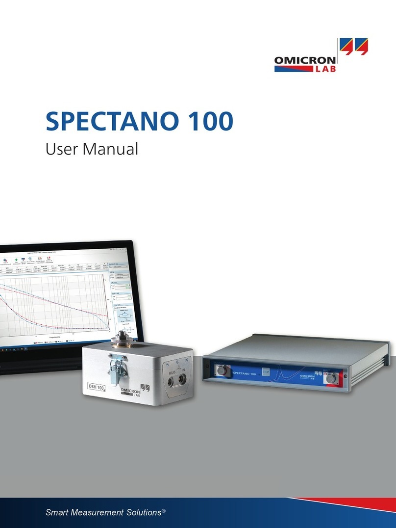
Omicron Lab SPECTANO 100 User manual

Smart Measurement Solutions®
SPECTANO 100
User Manual

Document Changes
FDS frequency range
7KH¿UVWVRIWZDUHYHUVLRQ63(&7$12$QDO\]HU6XLWH9SURYLGHVDIUHTXHQF\UDQJHIURP
+]WRN+]LQVWHDGRI+]WRN+]
$IUHTXHQF\UDQJHGRZQWR+]ZLOOEHDYDLODEOHZLWKWKHQH[WVRIWZDUHVHUYLFHUHOHDVH
www.dacpol.eu
XHQF\UDQJHIURP\UDQJHIURP
ZDUHVHUYLFHUHOHDVHZDUHVHUYLFHUHOHDVH

1
Contents
Contents
1 About this User Manual. . . . . . . . . . . . . . . . . . . . . . . . . . . . . . . . . . . . . . . . . .4
Safety symbols used . . . . . . . . . . . . . . . . . . . . . . . . . . . . . . . . . . . . . . . . . . . . . . 4
2 Safety instructions. . . . . . . . . . . . . . . . . . . . . . . . . . . . . . . . . . . . . . . . . . . . . .5
2.1 Operator qualifications and safety standards. . . . . . . . . . . . . . . . . . . . . . . . . . . . 5
2.1.1 Additional operator qualifications for testing with high and low voltage systems 5
2.2 Five safety rules. . . . . . . . . . . . . . . . . . . . . . . . . . . . . . . . . . . . . . . . . . . . . . . . . . 6
2.3 General . . . . . . . . . . . . . . . . . . . . . . . . . . . . . . . . . . . . . . . . . . . . . . . . . . . . . . . . 6
2.4 Operation . . . . . . . . . . . . . . . . . . . . . . . . . . . . . . . . . . . . . . . . . . . . . . . . . . . . . . . 6
2.5 Orderly measures . . . . . . . . . . . . . . . . . . . . . . . . . . . . . . . . . . . . . . . . . . . . . . . . 7
2.6 Designated use . . . . . . . . . . . . . . . . . . . . . . . . . . . . . . . . . . . . . . . . . . . . . . . . . . 7
2.7 Disclaimer . . . . . . . . . . . . . . . . . . . . . . . . . . . . . . . . . . . . . . . . . . . . . . . . . . . . . . 8
3 Compliance statements and recycling . . . . . . . . . . . . . . . . . . . . . . . . . . . . .9
3.1 Compliance statements . . . . . . . . . . . . . . . . . . . . . . . . . . . . . . . . . . . . . . . . . . . . 9
3.2 Recycling . . . . . . . . . . . . . . . . . . . . . . . . . . . . . . . . . . . . . . . . . . . . . . . . . . . . . . . 9
4 System requirements . . . . . . . . . . . . . . . . . . . . . . . . . . . . . . . . . . . . . . . . . .10
5 Introduction . . . . . . . . . . . . . . . . . . . . . . . . . . . . . . . . . . . . . . . . . . . . . . . . . .11
5.1 SPECTANO 100 . . . . . . . . . . . . . . . . . . . . . . . . . . . . . . . . . . . . . . . . . . . . . . . . 11
5.2 Methods . . . . . . . . . . . . . . . . . . . . . . . . . . . . . . . . . . . . . . . . . . . . . . . . . . . . . . . 11
5.3 DTS1 dielectric test sample box . . . . . . . . . . . . . . . . . . . . . . . . . . . . . . . . . . . . 12
5.4 Frequency domain spectroscopy (FDS) . . . . . . . . . . . . . . . . . . . . . . . . . . . . . . 12
5.5 Polarization current method (PDC) . . . . . . . . . . . . . . . . . . . . . . . . . . . . . . . . . . 12
5.6 Combined mode (FDS and PDC) . . . . . . . . . . . . . . . . . . . . . . . . . . . . . . . . . . . 13
5.7 Scope of delivery and ordering information . . . . . . . . . . . . . . . . . . . . . . . . . . . . 14
5.7.1 Main package . . . . . . . . . . . . . . . . . . . . . . . . . . . . . . . . . . . . . . . . . . . . . . . . . . 14
5.7.2 Optional accessories . . . . . . . . . . . . . . . . . . . . . . . . . . . . . . . . . . . . . . . . . . . . 15
6 Device description. . . . . . . . . . . . . . . . . . . . . . . . . . . . . . . . . . . . . . . . . . . . .16
6.1 SPECTANO 100 . . . . . . . . . . . . . . . . . . . . . . . . . . . . . . . . . . . . . . . . . . . . . . . . 16
6.1.1 Connectors and operating controls. . . . . . . . . . . . . . . . . . . . . . . . . . . . . . . . . . 16
6.1.2 Cleaning . . . . . . . . . . . . . . . . . . . . . . . . . . . . . . . . . . . . . . . . . . . . . . . . . . . . . . 19
6.2 DTS1 dielectric test sample box . . . . . . . . . . . . . . . . . . . . . . . . . . . . . . . . . . . . 19
7 Preparation of test material and test cell. . . . . . . . . . . . . . . . . . . . . . . . . . .21
7.1 Solid materials . . . . . . . . . . . . . . . . . . . . . . . . . . . . . . . . . . . . . . . . . . . . . . . . . . 21
7.1.1 Preparation of solid material test cells . . . . . . . . . . . . . . . . . . . . . . . . . . . . . . . 21
7.1.2 Preparation of solid test material . . . . . . . . . . . . . . . . . . . . . . . . . . . . . . . . . . . 21
7.1.3 Electrode adjustment of solid material test cells. . . . . . . . . . . . . . . . . . . . . . . . 22
7.2 Liquid materials . . . . . . . . . . . . . . . . . . . . . . . . . . . . . . . . . . . . . . . . . . . . . . . . . 23
7.2.1 Preparation of liquid material test cells . . . . . . . . . . . . . . . . . . . . . . . . . . . . . . . 23
www.dacpol.eu
..
. . . . . . . 4.4
. . . . . . . . .5. .
. . . . . . . . . . . . 5. . . . . . . . 5
ow voltage systems 5age systems 5
. . . . . . . . . . . . . . . . . 6. . . . . . . . .
. . . . . . . . . . . . . . . . . . . 6. . . . . . . . . . . . . . . . . .
. . . . . . . . . . . . . . . . . . . . . . 6. . . . . . . . . .
. . . . . . . . . . . . . . . . . . . . . . .. . . . . . . . . . . . . .
. . . . . . . . . . . . . . . . . . . . . . .. . . . . . . . . . . .
. . . . . . . . . . . . . . . . . . . . . . .. . . . . . . . .
g . . . . . . . . . . . . .. . . . . . . . . . .
. . . . . .
. . . . . . . . . . . . . . . . . . . . . . .. . . . . . . . . .
. . . . . . . . . . . . . . . . . . . . . . .. . . . . . . . . . . . . .
. . .
. . . . . . . . . . . .. . . . . . . .
. . . . . .. .
. . .
. . . . . . . . . . . . .. . . . . . . . . . .
. . . .
. . . . . . . . . . . . . . . . . . . . . . .. . . . . . . . . . . . . . . .
. . . . . . . . . . . . . . . . . . . . . .. . . . . . . . . . . . .
tric test sample box . . . . . . .sample box . .
cy domain spectroscopy (FDSspectroscopy
zation current method (PDC)current method (
ombined mode (FDS and PDCed mode (FDS a
Scope of delivery and orderiof delivery
5.7.1 Main package . . . .7.1 Main packag
5.7.2 Optional accesso.7.2 Optiona
Device description. .evice descripti
6.16.
SPECTANO 10SPECTA
6.1.1 Conne6.1.
6.1.2 Cle6.1.2
6.26.2
DTS1
d
7 Prepara7Pre
7.1

SPECTANO 100 User Manual
2
7.2.2 Preparation of liquid test material and filling the test cell . . . . . . . . . . . . . . . . . 23
8 Setup improvements. . . . . . . . . . . . . . . . . . . . . . . . . . . . . . . . . . . . . . . . . . .24
8.1 Error correction . . . . . . . . . . . . . . . . . . . . . . . . . . . . . . . . . . . . . . . . . . . . . . . . . 24
8.2 Electrodes for solid dielectric material analysis . . . . . . . . . . . . . . . . . . . . . . . . . 25
8.2.1 Thin film electrodes or coating . . . . . . . . . . . . . . . . . . . . . . . . . . . . . . . . . . . . . 26
8.2.2 Guard electrodes . . . . . . . . . . . . . . . . . . . . . . . . . . . . . . . . . . . . . . . . . . . . . . . 26
8.3 Stable environment . . . . . . . . . . . . . . . . . . . . . . . . . . . . . . . . . . . . . . . . . . . . . . 28
8.4 Shielding of low signal measurements . . . . . . . . . . . . . . . . . . . . . . . . . . . . . . . 28
9 Installation . . . . . . . . . . . . . . . . . . . . . . . . . . . . . . . . . . . . . . . . . . . . . . . . . . .29
9.1 Install SPECTANO Analyzer Suite . . . . . . . . . . . . . . . . . . . . . . . . . . . . . . . . . . 29
9.2 Power up SPECTANO 100 . . . . . . . . . . . . . . . . . . . . . . . . . . . . . . . . . . . . . . . . 30
9.3 Connect SPECTANO 100 to the computer . . . . . . . . . . . . . . . . . . . . . . . . . . . . 30
9.4 Connect SPECTANO 100 to a test object . . . . . . . . . . . . . . . . . . . . . . . . . . . . . 31
9.4.1 Typical setup for a test cell with guard ring. . . . . . . . . . . . . . . . . . . . . . . . . . . . 34
9.4.2 Typical setup for a test cell without guard ring . . . . . . . . . . . . . . . . . . . . . . . . . 35
9.5 Connect SPECTANO 100 to the DTS1 dielectric test sample box . . . . . . . . . . 37
10 SPECTANO Analyzer Suite. . . . . . . . . . . . . . . . . . . . . . . . . . . . . . . . . . . . . .39
10.1 Start view. . . . . . . . . . . . . . . . . . . . . . . . . . . . . . . . . . . . . . . . . . . . . . . . . . . . . . 39
10.2 Create a new test. . . . . . . . . . . . . . . . . . . . . . . . . . . . . . . . . . . . . . . . . . . . . . . . 41
10.3 Perform measurements . . . . . . . . . . . . . . . . . . . . . . . . . . . . . . . . . . . . . . . . . . . 43
10.4 Perform air reference measurements . . . . . . . . . . . . . . . . . . . . . . . . . . . . . . . . 44
10.4.1 Measurement procedure. . . . . . . . . . . . . . . . . . . . . . . . . . . . . . . . . . . . . . . . . . 44
10.4.2 Correction procedure . . . . . . . . . . . . . . . . . . . . . . . . . . . . . . . . . . . . . . . . . . . . 46
10.4.3 Correction logic and calculation . . . . . . . . . . . . . . . . . . . . . . . . . . . . . . . . . . . . 46
10.5 Perform analysis . . . . . . . . . . . . . . . . . . . . . . . . . . . . . . . . . . . . . . . . . . . . . . . . 47
10.6 View measurement results . . . . . . . . . . . . . . . . . . . . . . . . . . . . . . . . . . . . . . . . 47
10.6.1 Numerical results . . . . . . . . . . . . . . . . . . . . . . . . . . . . . . . . . . . . . . . . . . . . . . . 48
10.6.2 Graphical result view . . . . . . . . . . . . . . . . . . . . . . . . . . . . . . . . . . . . . . . . . . . . 49
10.6.3 Result view controls . . . . . . . . . . . . . . . . . . . . . . . . . . . . . . . . . . . . . . . . . . . . . 50
10.7 Settings . . . . . . . . . . . . . . . . . . . . . . . . . . . . . . . . . . . . . . . . . . . . . . . . . . . . . . . 51
10.8 Commands . . . . . . . . . . . . . . . . . . . . . . . . . . . . . . . . . . . . . . . . . . . . . . . . . . . . 56
10.9 Home view . . . . . . . . . . . . . . . . . . . . . . . . . . . . . . . . . . . . . . . . . . . . . . . . . . . . . 59
10.10Load from the device . . . . . . . . . . . . . . . . . . . . . . . . . . . . . . . . . . . . . . . . . . . . . 61
10.10.1 Automatic load from the device . . . . . . . . . . . . . . . . . . . . . . . . . . . . . . . . . . . . 61
10.10.2 Manual load from device. . . . . . . . . . . . . . . . . . . . . . . . . . . . . . . . . . . . . . . . . . 61
11 Troubleshooting . . . . . . . . . . . . . . . . . . . . . . . . . . . . . . . . . . . . . . . . . . . . . .62
11.1 USB connection and/or power supply is missing. . . . . . . . . . . . . . . . . . . . . . . . 62
11.2 Lost communication. . . . . . . . . . . . . . . . . . . . . . . . . . . . . . . . . . . . . . . . . . . . . . 62
11.3 Measuring small capacitances – increased noise level . . . . . . . . . . . . . . . . . . . 62
11.4 Backup file . . . . . . . . . . . . . . . . . . . . . . . . . . . . . . . . . . . . . . . . . . . . . . . . . . . . . 63
www.dacpol.eu
.2
. . . . 255
. . . . . . . 26
. . . . . . . . . 26. . .
. . . . . . . . . . . 28. . . . . . 28
. . . . . . . . . . . . . 28. . . . . . . . 2
. ..
. . . . . . . . . . . . .29. . . . . . .2
. . . . . . . . . . . . . . . . . . . 29. . . . . . . . . . . . . . .
. . . . . . . . . . . . . . . . . . . . . . 3. . . . . . . . .
. . . . . . . . . . . . . . . . . . . . . . .. . . . . . . . . . . .
. . . . . . . . . . . . . . . . . . . . . . .. . . . . . . . .
d ring. . . . . . . . . . . . . . . . . . . . .. . . . . . . . . . . . . . . .
t guard ring . . . . . . . . . . . . . . . .d ring . . . . . . . . . . .
TS1
dielectric test sample boxectric test sa
. . . . . . . . .. .
. . . . . . . . . . .. . . .
. . . . . . . . . . . . . . . . . . . . . . .. . . . . . . . . . . . . .
. . . . . . . . . . . . . . . . . . . . . .. . . . . . . . . . . . . .
nts . . . . . . . . . . . . . . . . . . . . .nts . . . . . . . . . . . . . .
nce measurements . . . . . . .measurements . .
ement procedure. . . . . . . . . . . .procedure. . . . . . .
ection procedure . . . . . . . . . . . .cedure . . . . .
orrection logic and calculation . .and calcula
rm analysis . . . . . . . . . . . . . .ysis . . . . . . . . . .
w measurement results . . .asurement resul
10.6.1 Numerical results . . . .umerical re
10.6.2 Graphical result view6.2 Graphical res
10.6.3 Result view contro6.3 Result v
10.7 Settings . . . . . . . . .7 Settings . . . . .
10.8 Commands . . . .10.8 Comman
10.9 Home view . .10.9 Home v
10.10Load from10.10Load
10.10.1 A
10.10
11 Troub11 T
11.1

3
Contents
12 Technical data . . . . . . . . . . . . . . . . . . . . . . . . . . . . . . . . . . . . . . . . . . . . . . . .64
12.1 Voltage source. . . . . . . . . . . . . . . . . . . . . . . . . . . . . . . . . . . . . . . . . . . . . . . . . . 64
12.2 Frequency domain spectroscopy (FDS) . . . . . . . . . . . . . . . . . . . . . . . . . . . . . . 64
12.3 Time domain current measurement (PDC) . . . . . . . . . . . . . . . . . . . . . . . . . . . . 64
12.4 Dissipation factor and capacitance . . . . . . . . . . . . . . . . . . . . . . . . . . . . . . . . . . 64
12.5 Measurement time (based on frequency) . . . . . . . . . . . . . . . . . . . . . . . . . . . . . 64
12.6 AC power supply data – input . . . . . . . . . . . . . . . . . . . . . . . . . . . . . . . . . . . . . . 65
12.7 AC power supply data – output . . . . . . . . . . . . . . . . . . . . . . . . . . . . . . . . . . . . . 65
12.8 Environmental and storage conditions. . . . . . . . . . . . . . . . . . . . . . . . . . . . . . . . 65
12.9 Mechanical data. . . . . . . . . . . . . . . . . . . . . . . . . . . . . . . . . . . . . . . . . . . . . . . . . 65
Support . . . . . . . . . . . . . . . . . . . . . . . . . . . . . . . . . . . . . . . . . . . . . . . . . . . . . .66
Technical support – get support . . . . . . . . . . . . . . . . . . . . . . . . . . . . . . . . . . . . 66
www.dacpol.eu
. .
. . . . . 64
64
. . . . . . . 64. . . 64
. . . . . . . . . . 64. . . . 6
. . . . . . . . . . . . . 65. . . . . . . . 65
. . . . . . . . . . . . . . . 65. . . . . . . . .
. . . . . . . . . . . . . . . . . . 65. . . . . . . . . . . . . . . . . .
. . . . . . . . . . . . . . . . . . . . 65. . . . . . . . . . . . . . .
. . . . . . . . .. . .
. . . . . . . . . . . .. . . . . . . .
. . . . . . . . . . . . . . . . . . . . . . .. . . . . . . . . . . .

SPECTANO 100 User Manual
4
1 About this User Manual
This SPECTANO 100 User Manual provides in-depth information about
SPECTANO 100, its installation, designated use, configuration and operation.
Moreover, it includes detailed description of SPECTANO Analyzer Suite. The
SPECTANO 100 User Manual is available in PDF format on the DVD delivered
with SPECTANO 100 and can be accessed directly on the OMICRON Lab
website www.omicron-lab.com.
Safety symbols used
In this User Manual, the following symbols indicate safety instructions for
avoiding hazards.
DANGER
Death or severe injury will occur if the appropriate safety instructions are not
observed.
WARNING
Death or severe injury can occur if the appropriate safety instructions are not
observed.
CAUTION
Minor or moderate injury may occur if the appropriate safety instructions are
not observed.
NOTICE
Equipment damage or loss of data possible
www.dacpol.eu
eration.
uite
. The
VD deliveredive
CRON Labb
cate safety instructions forety instructions
po
cpo
appropriate safety
acp
dac
y can occur if the
ap
d
w.d
or or moderate injury
obs
w
NOTICE
ww
Equipmen

5
Safety instructions
2 Safety instructions
Before operating SPECTANO 100 and its accessories, read the following safety
instructions carefully. If you do not understand some safety instructions, contact
OMICRON Lab before proceeding. When working with SPECTANO 100,
observe the five safety rules (see 2.2 "Five safety rules" later in this chapter) and
all other safety instructions in this User Manual.
You are responsible for every application that makes use of an OMICRON or
OMICRON Lab product. SPECTANO 100 may only be operated by trained
personnel. Any miss-operation can result in damage to property or persons.
Maintenance and repair of SPECTANO 100 and its accessories is only
permitted by qualified experts either at OMICRON Lab or at certified repair
centers.
2.1 Operator qualifications and safety standards
Testing and measuring with SPECTANO 100 and its accessories like the DTS1
dielectric test sample box must be carried out only by qualified, skilled and
authorized personnel working with voltages up to 200 Vpeak AC and DC.
Before starting to work, clearly establish the responsibilities. Personnel
receiving training, instructions, directions, or education on SPECTANO 100
must be under constant supervision of an experienced operator. Measuring with
SPECTANO 100must comply with the relevant national and international safety
standards:
• EN 50191 (VDE 0104) "Erection and Operation of Electrical Test
Equipment"
• EN 50110-1 (VDE 0105 Part 100) "Operation of Electrical Installations"
Moreover, observe all applicable regulations for accident prevention in the
country and at the site of operation.
The manufacturer or the distributors are not liable for damage resulting from
unintended usage. The user alone assumes all responsibility and risks.
2.1.1 Additional operator qualifications for testing with high and
low voltage systems
The operator must be:
• Familiar with recognized operating practices and procedures for working on
high and low voltage systems.
• Familiar with the five safety rules:
• Authorized to perform the required work on the equipment of the power
distribution network.
• Trained in the proper use of all necessary personal safety equipment.
www.dacpol.eu
safet
s, contact
act
100
,
s chapter) andter)
of an OMICRON orOMICRON or
operated by trainedd by trained
to property or persons.to property or persons.
its accessories is onlyaccessories is only
RON Lab or at certified repairor at certified
d safety standardsafety stand
PECTANO 100ANO
and its accessorand
must be
carried out only bycarried out only
quali
orking with voltages up to 200 Vwith voltages up to
ork, clearly establish they establish th
responsrespo
instructions, directions, or educuctions, directions, or educ
constant supervision ofnt supervision of
an experan
10010
must comply with the relevast comply with
0
:
N 50191 (VDE 0104) "Erection91 (VDE 0104) "Ere
Equipment"ent
• EN 50110-1 (VDE 0105 Pa0-1 (VDE 0
Moreover, observe all applreover, obse
country and at the site ocountry and at th
The manufacturer oThe manuf
unintended usagunintended
.1.1 Additional opeAdditiona
low voltagelow vo
Th

SPECTANO 100 User Manual
6
2.2 Five safety rules
Before connecting any test leads to a test object, always observe the five safety
rules for working with high power:
ŹDisconnect completely.
ŹSecure against re-connection.
ŹVerify that the installation is dead.
ŹCarry out grounding and short-circuiting.
ŹProvide protection against adjacent live parts.
2.3 General
ŹDo not touch any terminals without a visible connection to ground.
ŹBefore handling SPECTANO 100 in any way, connect its equipotential
ground (see Figure 6-2 "SPECTANO 100 rear view" on page 18) with a solid
connection of at least 6 mm2cross-section to a ground connection in the
laboratory.
ŹDo not open the SPECTANO 100 housing. Opening the device invalidates
all warranty claims!
ŹDo not repair, modify, extend, or adapt SPECTANO 100 or any accessories.
ŹUse only the delivered cables and the delivered grounded power supply.
ŹUse SPECTANO 100 and its accessories only in a technically sound
condition and when its use is in accordance with the local safety regulations.
In particular, avoid disruptions that could in turn affect safety.
2.4 Operation
ŹBefore operating SPECTANO 100, ground it as described in 2.3 "General"
on page 6.
ŹEnsure that the ground is in good condition, clean, and free of oxidation.
ŹBefore handling SPECTANO 100 in any way, ground any parts of the test
object which have to be connected to ground.
ŹAlways turn off SPECTANO 100 with the power switch before connecting or
disconnecting any cables.
ŹNever remove any cables from SPECTANO 100 or the test object during a
test.
DANGER
Death or severe injury caused by high voltage or current
ŹAlways observe the safety rules specified in 2 "Safety instructions" in this
User Manual.
www.dacpol.eu
ys observe the five safetythe five safet
rcuiting.g
djacent live parts.live parts.
y terminals without a visible coninals without a visible con
ling
SPECTANO 100PECTANO 100
in any wayin a
00
ee Figure 6-2 "SPECee Figure 6-2 "SPEC
TANO 100TA
tion of at least 6 mmof at least 6 m
22
cross-seccro
oratory.
Do not open thepen
SPECTANO 10SPEC
all warranty claims!ty claims!
Ź
Do not repair, modify, exteDo not repair, modif
ŹŹ
Use only the deliveredse only the d
ŹŹ
UseUse
SPECTANO 1SP
condition and whcondition
In particular,In p
2.4 OperationOpera
Ź
u

7
Safety instructions
2.5 Orderly measures
The SPECTANO 100 Quick Start Guide, SPECTANO 100 User Manual, or the
e-book version of one of these documents have always to be available on the
site where SPECTANO 100 is being used. All users of SPECTANO 100 must
read and observe the safety instructions described in the documents and all
relevant installation and operation instructions.
SPECTANO 100 and its accessories like the DTS1 dielectric test sample box
may be used only as described in the SPECTANO 100 Quick Start Guide or the
User Manual. Any other use is not in accordance with the local safety
regulations. The manufacturer and the distributor are not liable for damage
resulting from improper usage. The user alone assumes all responsibility and
risk.
Full compliance with the local safety regulations also includes following the
instructions provided in the SPECTANO 100 Quick Start Guide or the User
Manual.
2.6 Designated use
SPECTANO 100 and its accessories are especially designed for testing
dielectric solid and liquid materials together with a suitable dielectric material
test cell and test system.
Examples of dielectric material analysis use cases and applications:
SPECTANO 100 characterizes,
analyzes and determines the
insulation, polarization or dielectric
losses of solid and liquid materials
such as:
SPECTANO 100 achieves
information on:
• Electrical insulation paper/cellulose
• Nanomaterials (nano-composites)
• Dielectric components
• Epoxy resin
• Polymers
• Insulation oils
• Display technologies like glasses or
polymers
• Solar cells
•etc.
• Dielectric properties
• Material aging
• Material structure
• Space charges in multilayer
insulation
• Surface or film thickness of
coatings
• Curing processes
www.d
• Electrical insulatiElectrical in
on p
• Nanomaterials (n• Nanomate
wda
00
characterizes,
0
nd determines the
polarization or
olid and liquid
ch
dacpol.eu
r
on the
00
mustst
0
nts and all
ic test sample boxsample box
uick Start Guide or theart Guide or the
the local safetysafety
re not liable for damagere not liable for damage
ssumes aumes
ll responsibility andsibility a
lations also includes following ths also includes follow
O 100 Quick Start Guide or the Uuick Start Guide o
s accessories are especially desssories are especia
quid materials togeterials toget
her with a suher with
system.
dielectric materialdielectric material
analysis use canalysis
• Dielectric com• Dielec
• Epoxy res•E
• Polym
•Ins
•
ww
da
wd

SPECTANO 100 User Manual
8
2.7 Disclaimer
The advisory procedures and information contained within this document have
been compiled as a guide to the safe and effective operation of
SPECTANO 100. It has been prepared in conjunction with application engineers
and the collective experience of the manufacturer.
The in-service conditions for the use of SPECTANO 100 may vary between
customers and end-users.
Consequently, this document is offered as a guide only. It shall be used in
conjunction with the customers own safety procedures, maintenance program,
engineering judgment, and training qualifications.
If SPECTANO 100 or its accessories are used in a manner not specified by the
manufacturer or used with third party test devices and cables, the protection
provided by SPECTANO 100 or its accessories may be impaired, and this may
result in damage to property or persons.
www.dacpol.eu
v
ngineerss
ary betweenen
It shall be used ine used in
s, maintenance program,nce program
in a manner not specified by thener not specifi
vices and cables, the protectionand cables, the pro
sories may be impaired, and thismay be impaired,
s.

9
Compliance statements and recycling
3 Compliance statements and recycling
3.1 Compliance statements
3.2 Recycling
Declaration of conformity (EU)
The equipment adheres to the guidelines of the council of the European
Community for meeting the requirements of the member states regarding the
electromagnetic compatibility (EMC) directive, the low voltage directive (LVD)
and the RoHS directive.
FCC compliance (USA)
This equipment has been tested and found to comply with the limits for a
Class A digital device, pursuant to part 15 of the FCC Rules. These limits are
designed to provide reasonable protection against harmful interference when
the equipment is operated in a commercial environment. This equipment
generates, uses, and can radiate radio frequency energy and, if not installed
and used in accordance with the instruction manual, may cause harmful
interference to radio communications. Operation of this equipment in a
residential area is likely to cause harmful interference in which case the user
will be required to correct the interference at his own expense.
Changes or modifications not expressly approved by the party responsible for
compliance could void the user's authority to operate the equipment.
Declaration of compliance (Canada)
This Class A digital apparatus complies with Canadian ICES-003.
Cet appareil numérique de la classe A est conforme à la norme NMB-003 du
Canada.
This test set (including all accessories) is not intended for household
use. At the end of its service life, do not dispose of the test set with
household waste!
For customers in EU countries (incl. European Economic Area)
OMICRON test sets are subject to the EU Waste Electrical and Electronic
Equipment Directive 2012/19/EU (WEEE directive). As part of our legal
obligations under this legislation, OMICRON offers to take back the test set
and ensure that it is disposed of by authorized recycling agents.
For customers outside the European Economic Area
Please contact the authorities in charge for the relevant environmental
regulations in your country and dispose the OMICRON test set only in
accordance with your local legal requirements.
www.dacpol.eu
Recyclingecycling
e European
states regarding theregarding the
voltage directive (LVD)directive (LVD
nd to comply with the limits for aomply with the limits
15 of the FCC Rules. These limhe FCC Rules. Th
tection against harmful interferenainst harmful
ommercial environment. This equrcial environment. T
ate radioio
frequency energy and,frequency energy
h the instst
ruction manual, may caruction manu
munications. Operation of this ecations. Operation o
y to cause harmfuluse harmfu
interferenceinterfe
orrect the
interference atinterference at
his owhis
difications not expresslyions not expressly
approvea
could void the user's authority tocould void the user's auth
aration of compliance (Canadan of compliance (C
his Class A digital apparatusA digital appa
com
Cet appareil numérique de laappareil numérique
Canada.nad
www
www
w
ww
ww
ww
w
w
w
w
ww
w
w
w
w
w
w
w
w
www
www
w
w
w
w
w
w
eu
This test setThis
use. At th
househ
For
w
u
u
w.

SPECTANO 100 User Manual
10
4 System requirements
The following table shows the minimum requirements your computer needs to
run SPECTANO Analyzer Suite.
Table 4-1 SPECTANO Analyzer Suite system requirements
Characteristic Requirement
Operating system Windows 10 64-bit and 32-bit,
Windows 8.1 64-bit and 32-bit,
Windows 8 64-bit and 32-bit,
Windows 7 SP1 64-bit and 32-bit
CPU Current Intel or AMD CPU
RAM min. 2 GB
Graphics adapter Super VGA (1280×768) or higher-resolution video
adapter and monitor
Interface USB 2.0 or higher
2.0 or higherhigher
pol
(1280×768) or higher-resolution768) or higher-reso
nd monitorr
ol.eu
to
eu
it,
bit,
and 32-bitand
D CPU
eu
u
eu
le
ol.
ol
po
po

11
Introduction
5 Introduction
5.1 SPECTANO 100
SPECTANO 100, in conjunction with its accessories or as stand-alone unit, is a
test system for dielectric analysis of solid and liquid materials. It combines the
time-domain and frequency-domain analysis within a wide frequency range from
20 ȝHz up to 5 kHz in one device and provides an output voltage range from
100mVto200V
peak. The designated use of SPECTANO 100 is the analysis of
dielectric characteristics of liquid and solid materials such as:
• Impedance, capacitance and resistance
• Complex permittivity İ
• Loss factor tanį
SPECTANO 100 can be used for a wide range of different applications:
• Dielectric analysis of solid and liquid dielectric materials, for example,
polymers, cellulose-based materials, oil, and other insulation materials
• Monitoring of polymerization and hardening processes
• Analysis of nanocomposites
• Research on dielectrics
• Analysis of ceramics
• Analysis of thin films
5.2 Methods
The following list gives a short overview of methods and test cell types which can
be used together with SPECTANO 100to analyze dielectric materials. However,
also measurements of dielectric materials or components without electrode
arrangements are possible like capacitors or coils.
Solid dielectric materials:
• Parallel plate method
– Contacting electrode method used with rigid metal electrodes
– Contacting electrode method used with rigid metal electrodes and coated
solid test material
– Contacting electrode method used with thin film electrodes
– Non-contacting electrode method (gap occupied by air or liquid, on one or
both sides of the solid test material)
• Tube or cylindrical electrode method
Liquid dielectric materials:
• Coaxial probe method
• Parallel plate method
• Tube or cylindrical electrode method
www.dacpol.eu
alone unit, is anit
It combines thees th
equency range fromcy range from
voltage range frome range from
NO 100
is the analysis ofthe analysis
0
s such as:s s
wide range of different applicatioof different a
nd liquid dielectric materials, ford dielectric materia
d materials, oil, and other insularials, oil, and o
ization and hardening processen and hardening pr
ompositeses
ielectrics
f ceramicsmics
s of thin filmsof thin film
s
The following list gives a shortfollowing list gives a
be used together withused together with
SPEC
also measurements of dialso measureme
arrangements are posarrangements a
Solid dielectric mSolid diele
• Parallel p•Pa
–Con
–

SPECTANO 100 User Manual
12
5.3 DTS1 dielectric test sample box
The DTS1 dielectric test sample box is an accessory to SPECTANO 100 for
demonstrating and testing the functionality of SPECTANO 100 without a sample
test cell. The DTS1 is a demo box containing two samples: a high-precision,
low-loss 1 nF capacitor and a RC circuit simulating a dielectric sample with
losses. The main application areas of the DTS1 are in training and
demonstration purposes but it can also be used for detecting errors in a cable
setup.
5.4 Frequency domain spectroscopy (FDS)
By using the frequency domain spectroscopy (FDS), the dielectric properties of
the solid or liquid material under test are measured by frequency sweep (3 μHz
to 5 kHz). The FDS allows fast measurements at high frequencies but requires
long measurement times at lower frequencies.
5.5 Polarization current method (PDC)
In the polarization current (PDC) method, a DC voltage is applied to the device
under test for a specific time and the polarization current is measured. From the
polarization current, the dielectric response is evaluated and the dielectric
frequency characteristic is calculated using Fourier transformation. The PDC
method is faster than the FDS at very low frequencies, but the upper frequency
is limited due to the finite rise time of the DC pulse. The test frequency range for
the PDC method is 20 μHz to 100 mHz.
www.dacpol.eu
ample
cision,
ple with
nd
errors in a cablen a cable
DS)DS
FDS), the dielectric properties odielectric prop
asured by frequency sweep (3 μd by frequency swe
ments at high frequencies but reqt high frequencies
uencies.
thod (PDC)d (PDC)
t (PDC) method, a DC voltage is) method, a DC vol
c time and the polarization currend the polarization c
the dielectric reselectric re
ponse is evaluse is evalu
cteristic isc is
calculated using Fouricalculated using
er than the FDS at veryer than the FDS at ve
low frequ
e to the finite rise time of the DCo the finite rise time of
method is 20 μHz to 100 mHz.od is 20 μHz to 100

13
Introduction
5.6 Combined mode (FDS and PDC)
SPECTANO 100 combines the PDC with the FDS principle and thus
significantly reduces the testing time to exclusive frequency domain
measurements. PDC measurements can be accomplished in a short time but
are limited to low frequencies while FDS measurements are feasible for high
frequencies but take very long at low frequencies. It combines the advantages
of both principles. It measures data in the time domain for frequencies below
100 mHz. This reduces the measurement time up to 75% compared to exclusive
FDS measurements. For example, a FDS measurement from 1 kHz to 100 μHz
will take 11 hours, SPECTANO 100 will acquire this data in less than 3 hours
using the combined FDS and PDC measurement. The maximum test frequency
range for the combined mode is 20 μHz to 5 kHz.
Figure 5-1 Comparison of measurement methods
Test duration Frequency band
FDS
PDC
Combined
www.dacp
Comparison of measurementComparison of measure
Hz.
ol.eu
time butt
ble for high
he advantagesantag
equencies belowcies below
ompared to exclusiveed to exclusive
t from 1 kHz to 100 μHzkHz to 100 μH
data in less than 3 hoursthan 3 hours
The maximum test frequencyhe maximum test freque
C
e

SPECTANO 100 User Manual
14
5.7 Scope of delivery and ordering information
5.7.1 Main package
Description Part No. Picture
SPECTANO 100 main device OL000400
DTS1 dielectric sample test box
2 ×Triaxial standard cable
(1.5 m)
(–55 ºC to +250 ºC)
Specific grounded
SPECTANO 100 power supply
CD ROM incl.SPECTANO
Analyzer Suite and User
Manual (English)
Quick Start Guide (printed)
(English)
USB cable (1.5 m)
www.dacpol
ndednde
O 100100
power supplypower supp
CD ROM incl.RO
SPECTANO
Analyzer SuiteAnalyzer Suite
and Useran
Manual (English)Manual (E
Quick Sta
(Englis
ol.eu
eu
u
eu

15
Introduction
5.7.2 Optional accessories
Description Part No. Picture
2 ×Triaxial-to-4 mm plug
adapter cable set
(–40 ºC to +80 ºC)
OL000451
2 ×Triaxial-to-BNC connector
adapter cable set
(–55 ºC to +250 ºC)
OL000452
www.dacpol
po
u
u
le
leu

SPECTANO 100 User Manual
16
6 Device description
6.1 SPECTANO 100
6.1.1 Connectors and operating controls
Figure 6-1 SPECTANO 100 front view
DANGER
Death or severe injury caused by high voltage or current
ŹDo not touch the OUTPUT connector when the red LED is on or blinks.
ŹAlways ensure that no dangerous voltages are present at any touchable
part of the device.
ŹBefore handling SPECTANO 100 in any way, connect its equipotential
ground terminal with a solid connection of at least 6 mm2cross-section to
the ground terminal in the laboratory.
OUTPUT connector
Measurement voltage: 200 Vpeak
Max. continuous output current: 50 mApeak
Max. output frequency: 5 kHz INPUT connector
STOP button
Stops measurements
Yellow LED
See Table 6-1 "Signal LEDs"
on page 17
Green LED
See Table 6-1 "Signal LEDs"
on page 17
Red LED
See Table 6-1 "Signal LEDs"
on page 17
www.dacpol.eu
Figure 6-1Figure 6-1
SPE
eu
pol.eu
red LED is on or blinks.
esent
cha
y, connect its equ
t least 6 mm
cro
d
d
c
peak
ac
acp
cp
cp
OP
button
tops measu
a
a
d
d
w.d
LED
able 6-1 "Signa
on page 17

17
Device description
Table 6-1 Signal LEDs
LED State Description
Green On Signals that the power switch is on.
Yellow Blinking
Signals the input activity:
• Measurement results are available in
SPECTANO 100 which are not saved.
(This can happen when the computer is
disconnected from SPECTANO 100 after the
measurement was started.).
• An error has occurred during measurement
(Measurement is stopped.). After a computer
has been connected to SPECTANO 100, the
error information is sent to the computer and
the LED is on.
Red
On or
blinking
Signals dangerous voltage on the OUTPUT
connector.
Blinking A measurement is running.
On for
approx.
10 s
The test object is being depolarized after a
measurement has been stopped by SPECTANO
Analyzer Suite, manually or due to an error.
www.dacp
prox.
0s
The test object is being dhe test object is be
measurement has beeeasurement has be
Analyzer SuiteAnalyzer Suit
, man
a
cp
A measurement is running.measurement is run
cpo
nals dangerous voltage on theangerous voltage on
O
connector.or.
pol.eu
u
ailable inn
e not saved.saved.
n the computer ismputer is
PECTANO 100100
after theafter the
00
s started.).start
occurred during measurementduring meas
ment is stoppedstopped
.). After a comput.). After a c
n connected toected to
SPECTANO 100SPECTA
nformation is sent to the compuon is sent to the c
LED is on.
u
u
u
po
cp
cp
ac

SPECTANO 100 User Manual
18
Figure 6-2 SPECTANO 100 rear view
DANGER
Death or severe injury caused by high voltage or current
ŹDo not handle SPECTANO 100 without grounding it.
ŹBefore handling SPECTANO 100 in any way, connect its equipotential
ground with a solid connection of at least 6 mm2cross-section to a ground
connection in the laboratory.
DANGER
Death or severe injury caused by high voltage or current
ŹDo not use power outlets without protective ground (PE).
ŹOnly use the delivered grounded AC power supply DRA SUPPLY to power
SPECTANO 100.
ŹConnect the SPECTANO 100 power supply only to a power outlet that is
equipped with protective ground (PE).
ŹFor safe operation always make sure that protective ground and
equipotential ground are connected properly.
DC power input
Connect only the especially designed and
optimized delivered power supply DRA SUPPLY
for testing with SPECTANO 100.
5 V DC output
Optional: for connecting a USB isolator
I/0 (on/off) power switch Equipotential ground
For connecting an external ground
USB connector
For connecting SPECTANO 100 to a computer
with a USB 2.0 A/A cable
www.dacpol.eu
F
eu
ial
ound
le
cpol.e
curre
und (PE).
supply
DRA SUPP
supply only to a po
PE).
sure that prote
nnected properly.
d
da
dacp
esigned and
supp
DRA SUPPLY
SPECTANO 1
wd
w.d
ww
I/0 (on/off) pow
Other manuals for SPECTANO 100
2
This manual suits for next models
1
Table of contents
Other Omicron Lab Measuring Instrument manuals

Omicron Lab
Omicron Lab CT Analyzer User manual

Omicron Lab
Omicron Lab Bode 100 User manual

Omicron Lab
Omicron Lab CP AL1 User manual

Omicron Lab
Omicron Lab OTMC 100 User manual

Omicron Lab
Omicron Lab Bode 100 User manual

Omicron Lab
Omicron Lab SPECTANO 100 User manual

Omicron Lab
Omicron Lab SPECTANO 100 User manual