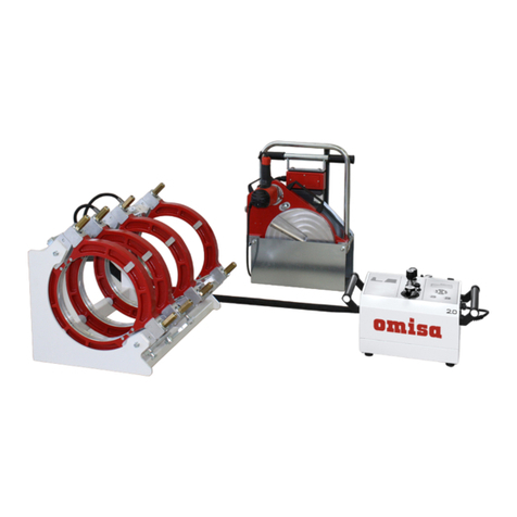
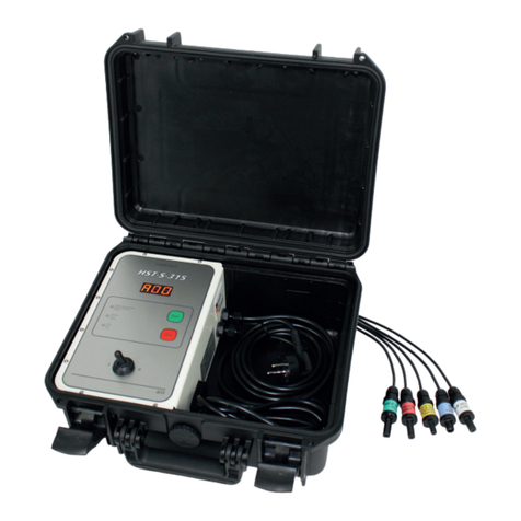
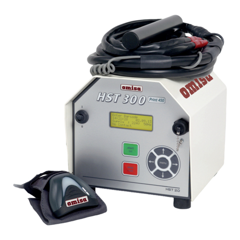
omisa HST 300 2.0 User manual

HST – S – 160
Versione Aprile 2020
O.M.I.S.A. S r l
Via Verga 9/11
20845 Sovico (MB)
+39 039 2323028
http://www.omisa.it
Manuale d'uso
• User’s Manual
Bedienungsanleitung •
Manuel utilisateur

La versione tedesca qui inclusa è il testo originale del manuale, dal quale vennero elaborate le incluse traduzioni.
The German version of the manual enclosed herein is the original copy, reected in the translations herein.
Inliegende deutsche Fassung der Anleitung ist der Urtext, welchen inliegende Übersetzungen wiedergeben.
La version allemande ci-après représente le texte original du manuel, rendu par les traductions ci-joint.

Versione Aprile 2020 IT 3
Manuale d'uso HST – S – 160
O.M.I.S.A. S r l
Via Verga 9/11
20845 Sovico (MB),
Italia
Indice
1 Introduzione........................................................................................................ 5
2 Messaggi di sicurezza ......................................................................................... 5
2.1 Uso improprio dei cavi di saldatura e di alimentazione................................... 5
2.2 Protezione del raccordo e del giunto................................................................ 5
2.3 Pulizia del prodotto............................................................................................ 5
2.4 Apertura dell'unità ............................................................................................. 6
2.5 Controllo del prodotto per danni...................................................................... 6
2.6 Alimentazione di rete......................................................................................... 6
3 Manutenzione..................................................................................................... 6
3.1 Assistenza e riparazione..................................................................................... 6
3.2 Trasporto, conservazione, spedizione................................................................ 6
4 Principio di funzionamento................................................................................ 7
5 Funzionamento................................................................................................... 7
5.1 Accensione dell'unità di saldatura..................................................................... 7
5.2 Collegamento del raccordo................................................................................ 7
5.3 Processo di saldatura .......................................................................................... 7
5.4 Fine della saldatura............................................................................................. 7
5.5 Processo di saldatura interrotto......................................................................... 8
5.6 Tempo di raffreddamento.................................................................................. 8
5.7 Ritorno all'inizio del processo............................................................................ 8
5.8 Utilizzo del adattatore multiplo ........................................................................ 8
6 Panoramica delle funzioni di automonitoraggio .................................................8
6.1 Errore di sistema ................................................................................................. 8
6.2 Erogazione rete rotta ......................................................................................... 8
6.3 Contatto interrotto............................................................................................. 8
6.4 Sottotensione...................................................................................................... 9
6.5 Sovratensione...................................................................................................... 9
6.6 Errore temperatura o la sua rilevazione difettosa............................................ 9
6.7 Errore frequenza................................................................................................. 9
6.8 Corrente molto bassa o molto alta.................................................................... 9
6.9 Blocco emergenza............................................................................................... 9
6.10 Saldatura ripetuta............................................................................................... 9
7 Speciche tecniche.............................................................................................. 9
8 Contatti per l'assistenza e la riparazione ........................................................ 10
9Accessori/pezzi per il prodotto......................................................................... 10

Versione Aprile 2020
4 IT Manuale d'uso HST – S – 160
O.M.I.S.A. S r l
Via Verga 9/11
20845 Sovico (MB),
Italia

Versione Aprile 2020 IT 5
Manuale d'uso HST – S – 160
O.M.I.S.A. S r l
Via Verga 9/11
20845 Sovico (MB),
Italia
1 Introduzione
Gentile cliente:
Grazie per aver acquistato il nostro prodotto. Siamo duciosi che soddisferà
le tue aspettative.
L’unità di saldatura HST – S – 160 è progettata esclusivamente per la salda-
tura dei tubi di scarico con raccordi elettrosaldabili in PE.
L’unità è stata prodotta e controllata secondo una tecnologia all’avan-
guardia e regolamenti di sicurezza ampiamente riconosciuti con adeguate
caratteristiche di sicurezza.
Prima della spedizione, è stata controllata l’afdabilità delle operazioni e
la sicurezza. In caso di errori di gestione o uso improprio, tuttavia, possono
essere esposti a pericoli:
• la salute dell’operatore,
• il prodotto e altro hardware dell’operatore,
• l’efciente funzionamento del prodotto.
Tutti i soggetti coinvolti nell’installazione, funzionamento, manovra e
manutenzione del prodotto devono:
• essere adeguatamente qualicati,
• utilizzare il prodotto solo sotto osservazione,
• rispettare e conoscere le istruzioni di questo manuale di istruzioni
prima di operare.
Grazie!
2 Messaggi di sicurezza
2.1 Uso improprio dei cavi di saldatura e di
alimentazione
Non movimentare il prodotto dai cavi e non tirare il cavo di alimentazione
per scollegare l’unità dalla presa. Proteggere i cavi dal calore, olio e bordi
taglienti.
2.2 Protezione del raccordo e del giunto
Utilizzare morsetti di posizionamento o un allineatore per ssare il rac-
cordo e il giunto da realizzare prima della saldatura. E’ vietato l’utilizzo
della saldatrice nei lavori in cui potrebbe venir a contatto con acqua. Non
utilizzare in caso di pioggia.
In particolare nei lavori in cui la posa è prevista interrata/sotto terra scavata,
si deve vericare sulla base delle normative locali che l’utilizzo considerato
sia autorizzato servendosi della saldatrice e che tutti gli sfogatoi e condut-
ture siano conformi alle disposizioni messe in vigore da quelle normative
a proposito di questo tipo di lavoro.
2.3 Pulizia del prodotto
Il prodotto non deve essere bagnato o immerso in acqua.

Versione Aprile 2020
6 IT Manuale d'uso HST – S – 160
O.M.I.S.A. S r l
Via Verga 9/11
20845 Sovico (MB),
Italia
2.4 Apertura dell'unità
Attenzione
La copertura del prodotto può essere rimossa solo da personale
autorizzato dal produttore/venditore o da un centro di assistenza
adeguatamente formato e autorizzato.
2.5 Controllo del prodotto per danni
Prima di ogni utilizzo del prodotto, vericare le caratteristiche di sicurezza e
possibilmente le parti esistenti con lievi danni per il corretto funzionamento.
Assicurarsi che i terminali di connessione funzionino correttamente, che il
contatto sia fermamente saldo e che le superci di contatto siano pulite.
Tutte le parti devono essere installate correttamente e conformi afnché
il prodotto funzioni come previsto. Caratteristiche o parti funzionali dan-
neggiate devono essere adeguatamente riparate o sostituite da un centro
di assistenza autorizzato.
2.6 Alimentazione di rete
Requisiti di cablaggio del fornitore di servizi di pubblica utilità, le regole
di sicurezza sul lavoro, le norme CEN e altre applicabili e i codici nazionali
devono essere rispettate.
La protezione del fusibile dell’alimentazione di rete deve essere di 10 A
al massimo.
L’unità deve essere protetta da pioggia e umidità.
3 Manutenzione
3.1 Assistenza e riparazione
Poiché il prodotto viene utilizzato per applicazioni soggette a considera-
zioni particolari di sicurezza, può essere riparato e revisionato solo dal pro-
duttore o dal suo partner/rivenditore debitamente autorizzato e formato.
In questo modo vengono garantiti elevati standard di qualità e sicurezza.
Importante
Il mancato rispetto di questa disposizione dispenserà il produttore
da qualsiasi garanzia e responsabilità per reclami sul prodotto,
compreso qualsiasi eventuale danno indiretto.
Quando viene revisionata, l’unità viene automaticamente aggiornata alle
speciche tecniche del prodotto al momento della revisione e viene assi-
curata una garanzia funzionale di tre mesi sull’unità revisionata.
Si consiglia di far revisionare il prodotto almeno ogni dodici mesi.
Eventuali disposizioni di legge relative a periodici controlli di sicurezza
elettrica devono essere rispettate.
3.2 Trasporto, conservazione, spedizione
Il prodotto viene spedito in una scatola di cartone.
Il prodotto deve essere conservato in questa scatola, per proteggerlo
dall’umidità ambientale.
Quando si spedisce l’unità, deve essere sempre inserita nella scatola.

Versione Aprile 2020 IT 7
Manuale d'uso HST – S – 160
O.M.I.S.A. S r l
Via Verga 9/11
20845 Sovico (MB),
Italia
4 Principio di funzionamento
La HST – S – 160 consente la saldatura di raccordi elettrosaldabili desti-
nati alla posa di condutture di scarico in PE nell’ambito degli impianti
domestici, delle marche Geberit, Akatherm-Euro, Coes, Valsir, Waviduo e
Vulcathene-Euro.
Il microprocessore che controlla la saldatrice HST – S – 160
• controlla e monitora completamente il processo di saldatura in mo-
dalità automatizzata,
• determina la durata della saldatura in base alla temperatura ambiente,
• mostra tutte le informazioni a mezzo di tre indicatori led e un display
sette segmenti.
Ulteriori accessori opzionali
• Cassa di trasporto
• Raschia-tubo manuale
5 Funzionamento
5.1 Accensione dell'unità di saldatura
Dopo aver collegato il cavo all’alimentazione principale 230 V, accendere
l’unità di saldatura usando l’interruttore On/Off. L‘unità quindi effettua un
autotest. Tutti e tre gli indicatori led si attivano simultaneamente per un
momento, indicando così che la saldatrice è pronta. In più, il display sette
segmenti fa vedere per c. 1 sec il modo di funzionamento H00. Successiva-
mente sia gli indicatori che il display si spengono.
5.2 Collegamento del raccordo
Collegare i terminali al raccordo e vericare il corretto ssaggio. Le superci
di contatto dei terminali e del raccordo devono essere pulite. Terminali
sporchi possono portare a una saldatura impropria e anche al surriscalda-
mento dei terminali stessi.
Importante
Se si utilizza il cosiddetto adattatore multiplo che consente la
saldatura simultanea di due raccordi, aver cura di collegarli cor-
rettamente, come descritto alla sezione 5.8.
Quando il raccordo è collegato, si attiva il led giallo (raccordo collegato).
In più, il tempo di saldatura viene indicato sul display. Premendo il tasto
START, si dà inizio al processo di saldatura.
Il tempo di saldatura nisce dopo 80 sec circa.
5.3 Processo di saldatura
Il processo di saldatura è monitorato per tutta la sua durata applicando i
parametri di saldatura determinati per il raccordo collegato.
5.4 Fine della saldatura
Il processo di saldatura termina correttamente se il tempo di saldatura è
giunto a 0 (000 sul display), il led verde (ne) si è acceso e il cicalino viene
sentito due volte.

0
00
0
Versione Aprile 2020
8 IT Manuale d'uso HST – S – 160
O.M.I.S.A. S r l
Via Verga 9/11
20845 Sovico (MB),
Italia
5.5 Processo di saldatura interrotto
Il processo di saldatura ha esito negativo se si accende il led rosso (guasto)
e il segnale acustico suona ad intervalli, oltre a ciò un codice di errore viene
visualizzato sul display.
L’errore deve essere accettato premendo il tasto STOP.
5.6 Tempo di raffreddamento
Il tempo di raffreddamento come indicato nelle istruzioni del produttore
del raccordo deve essere rispettato. Si prega di notare che in quel periodo
di tempo il raccordo è ancora caldo e non deve essere sottoposto a solle-
citazioni esterne.
5.7 Ritorno all'inizio del processo
Al termine della saldatura, scollegando il raccordo saldato dall’unità, la
stessa si resetterà all’inizio del processo di saldatura, in modo da evitare che
lo stesso raccordo per sbaglio venga saldato più volte. E’ anche indispen-
sabile scollegare la saldatrice dal raccordo dopo la saldatura, sia corretta
che con esito irregolare, perché essa sia pronta all’operazione successiva.
5.8 Utilizzo del adattatore multiplo
Il cosiddetto adattatore multiplo, ottenibile opzionalmente, è un cavo di
giunzione che consente la saldatura simultanea di due raccordi negli
interventi con raccordi elettrosaldabili di dimensione nominale
<DE 110 mm. I due raccordi devono essere dello stesso tipo e chie-
dere gli stessi parametri di saldatura. Con il cavo adattatore, i due
raccordi vengono, per così dire, collegati in serie. Il terminale di
saldatura giallo viene collegato a uno dei raccordi assieme al
connettore giallo del cavo adattatore, conseguentemente il
connettore nero del adattatore multiplo al raccordo dove si
collega anche il terminale nero del cavo di saldatura.
6 Panoramica delle funzioni di automonitoraggio
6.1 Errore di sistema
Attenzione
La saldatrice deve essere scollegata immediatamente sia dall’a-
limentazione che dal raccordo. L’auto-test ha rilevato un errore
nel sistema. La saldatrice non deve più essere accesa e deve essere
inviata a un centro autorizzato per essere controllata e riparata.
6.2 Erogazione rete rotta
L’ultima saldatura è incompleta. La saldatrice è stata disconnessa dall’ali-
mentazione mentre era in corso la saldatura. Questo errore deve essere
confermato premendo il tasto STOP.
6.3 Contatto interrotto
Non vi è un contatto elettrico correttamente stabilito tra la saldatrice e il
raccordo (controllare il morsetto a pressione sul raccordo) o la resistenza
è difettosa.

0
0
0
0
0
0
0
Versione Aprile 2020 IT 9
Manuale d'uso HST – S – 160
O.M.I.S.A. S r l
Via Verga 9/11
20845 Sovico (MB),
Italia
6.4 Sottotensione
La tensione in ingresso è inferiore a 180 volt. Regolare la tensione in uscita
del generatore.
6.5 Sovratensione
La tensione in ingresso è superiore a 280 volt. Ridurre la tensione in uscita
del generatore.
6.6 Errore temperatura o la sua rilevazione difettosa
La temperatura ambiente misurata è al di fuori del range di funzionamento
dell’unità di saldatura, cioè inferiore a – 5°C o oltre + 40°C.
Se questo errore si visualizza durante l’autotest, il sensore che rileva la
temperatura ambiente è danneggiato o difettoso.
6.7 Errore frequenza
La frequenza della tensione in ingresso è fuori tolleranza (40 Hz - 70 Hz).
6.8 Corrente molto bassa o molto alta
Il messaggio viene visualizzato se c’è un momentaneo guasto di corrente
o se il regolatore di corrente è difettoso.
6.9 Blocco emergenza
La saldatura è stata interrotta premendo il tasto STOP.
6.10 Saldatura ripetuta
Dopo la saldatura, non si è scollegato il raccordo dalla saldatrice e si è
cercato di riavviare una saldatura con lo stesso raccordo.
7 Specichetecniche
Tensione nominale 230 V
Frequenza 50 / 60 Hz
Potenza 1200 VA in ciclo di 80%
Grado di protezione IP 54
Corrente primaria max. 10 A
Range di temp. ambiente – 5°C a + 70 °C
Corrente in uscita max. 5 A
Tolleranze:
Temperatura ± 5 %
Corrente ± 2 %
Ai sensi della direttiva 2012/19/EU relativa ai riuti di apparecchiature
elettriche ed elettroniche (la cosiddetta direttiva RAEE), le apparecchiature
che sono state fabbricate o distribuite da noi, possono anche essere a noi
restituite. Per discutere l’esatta procedura che seguiremo, vi preghiamo di
contattarci con i suddetti dettagli.
Dichiariamo inoltre che la fabbricazione dell’attrezzatura è conforme
alla direttiva 2011/65/EU sulla restrizione dell’uso di alcune sostanze pe-
ricolose nelle apparecchiature elettriche ed elettroniche (la cosiddetta
Direttiva RoHS).

Versione Aprile 2020
10 IT Manuale d'uso HST – S – 160
O.M.I.S.A. S r l
Via Verga 9/11
20845 Sovico (MB),
Italia
8 Contatti per l'assistenza e la riparazione
O.M.I.S.A. S r l
Via Verga 9/11 Tel.: +39 039 23 23 028
20845 Sovico (MB), Italia
Info
Ci riserviamo il diritto di modicare le speciche tecniche
del prodotto senza preavviso.
9Accessori/pezzi per il prodotto
Adattatore multiplo HST – S per saldatura simultanea 402 - 300 - 002

Version April 2020 EN 3
HST – S – 160 User’s Manual
O.M.I.S.A. S r l
Via Verga 9/11
20845 Sovico (MB),
Italy
Contents
1 Introduction ........................................................................................................ 5
2 Safety Messages .................................................................................................. 5
2.1 Improper Use of the Welding and Power Supply Cables ................................. 5
2.2 Securing the Fitting and the Joint ..................................................................... 5
2.3 Cleaning the Welding Unit................................................................................. 5
2.4 Opening the Unit................................................................................................ 6
2.5 Checking for Damage......................................................................................... 6
2.6 Mains Power Supply............................................................................................ 6
3 Service.................................................................................................................. 6
3.1 Maintenance and Repair .................................................................................... 6
3.2 Transport, Storage, Shipment ............................................................................ 6
4 Principle of Operation ........................................................................................ 7
5 Operation ............................................................................................................ 7
5.1 Turning the Welding Unit On............................................................................. 7
5.2 Connecting the Electrofusion Fitting................................................................. 7
5.3 Welding Process .................................................................................................. 7
5.4 End of Welding ................................................................................................... 7
5.5 Aborted Welding ................................................................................................ 8
5.6 Cooling Time ....................................................................................................... 8
5.7 Returning to the Start of Welding..................................................................... 8
5.8 Using the Optional Multi-adapter ..................................................................... 8
6 Self-Monitoring Functions Overview................................................................. 8
6.1 System Error ........................................................................................................ 8
6.2 Power Supply Failure .......................................................................................... 8
6.3 No Contact........................................................................................................... 8
6.4 Low Voltage ........................................................................................................ 9
6.5 Overvoltage......................................................................................................... 9
6.6 Temperature Error or Temperature Sensor Defective ...................................... 9
6.7 Frequency Error................................................................................................... 9
6.8 Low or Excess Current......................................................................................... 9
6.9 Emergency Off .................................................................................................... 9
6.10 Used Fitting Error................................................................................................ 9
7 TechnicalSpecicationsoftheProduct ............................................................. 9
8 Service and Repair Contact............................................................................... 10
9 Accessories for the Product .............................................................................. 10

Version April 2020
4 EN HST – S – 160 User’s Manual
O.M.I.S.A. S r l
Via Verga 9/11
20845 Sovico (MB),
Italy

Version April 2020 EN 5
HST – S – 160 User’s Manual
O.M.I.S.A. S r l
Via Verga 9/11
20845 Sovico (MB),
Italy
1 Introduction
Dear Customer:
Thank you very much for purchasing our product. We are confident
that it will meet your expectations.
The HST – S – 160 Electrofusion Welding Unit is designed exclusively
for jointing PE discharge lines assembled with electrofusion fittings.
The product was manufactured and checked according to state-of-
the-art technology and widely recognized safety regulations and is
equipped with the appropriate safety features.
Before shipment, it was checked for operation reliability and safety.
In the event of errors of handling or misuse, however, the following
may be exposed to hazards:
• theoperator’shealth,
• theproductandotherhardwareoftheoperator,
• theefficientworkoftheproduct.
All persons involved in the installation, operation, maintenance, and
service of the product have to
• beproperlyqualified,
• operatetheproductonlywhenobserved,
• readcarefullyandconformtotheUser’sManualbeforeworking
with the product.
Thank you.
2 Safety Messages
2.1 Improper Use of the Welding and Power Supply
Cables
Do not carry the product by one of its cables and do not pull the power
cord to unplug the unit from the socket. Protect the cables against
heat, oil, and cutting edges.
2.2 Securing the Fitting and the Joint
Use appropriate clamps where necessary to secure the fitting and the
joint before welding. The welding unit is intended exclusively for
applications where contact with water is not possible. It must not be
used in the rain.
In particular for buried/in-backfill installations, verify against the rel-
evant local standards that the welder may be used for the intended
application and that all drains and pipelines comply with the require-
ments stipulated by such standards for the intended application.
2.3 Cleaning the Welding Unit
The preoduct must not be sprayed with or immersed in water.

Version April 2020
6 EN HST – S – 160 User’s Manual
O.M.I.S.A. S r l
Via Verga 9/11
20845 Sovico (MB),
Italy
2.4 Opening the Unit
Caution
The cover of the product may be removed only by specialized
staff with the manufacturer/seller or with a partner organiza-
tion properly trained and approved by them.
2.5 Checking for Damage
Every time before operating the product, carefully check safety fea-
tures or possibly existing parts with minor damage for intended and
proper function. Make sure that the push-on connection terminals
work properly, that contact is fully established, and that the contact
surfaces are clean. All parts have to be installed correctly and properly
conform to all conditions in order for the operator to be sure that the
product works as intended. Damaged safety features or functional
parts should be properly repaired or replaced by a qualified organi-
zation/service shop.
2.6 Mains Power Supply
Utility suppliers’ wiring requirements, occupational safety rules, CEN
and other standards as well as national codes have to be respected.
Mains power fuse protection should be max. 10 A.
The product has to be protected against rain and humidity.
3 Service
3.1 Maintenance and Repair
As the product is used in applications that are sensitive to safety con-
siderations, it may be serviced and repaired only by the manufacturer
or its duly authorized and trained partners. Thus, constantly high
standards of operation quality and safety are maintained.
Important
Failure to comply with this provision will dispense the
manufacturer from any warranty and liability claims for the
product, including any consequential damage.
When serviced, the unit is upgraded automatically to the technical
specifications of the product at the moment it is serviced, and we grant
a three-month functional warranty on the serviced unit.
We recommend having the product serviced at least every twelve
months.
Any provisions on regular electrical safety check-ups will have to be
respected.
3.2 Transport, Storage, Shipment
The product is shipped in a cardboard box.
Store the product in the box dry and protected against humidity.
When shipped, the product should be placed into the box at any
time.

Version April 2020 EN 7
HST – S – 160 User’s Manual
O.M.I.S.A. S r l
Via Verga 9/11
20845 Sovico (MB),
Italy
4 Principle of Operation
The HST – S – 160 welding unit allows using electrofusion fittings
to join discharge lines used in HVACR applications and made of PE,
of the makes Geberit, Akatherm-Euro, Coes, Valsir, Waviduo, and
Vulcathene-Euro.
The microprocessor-controlled unit:-
• controlsandmonitorstheweldingprocessinafullyautomated
fashion,
• determineswelding durationdepending on ambienttempera-
ture,
• indicatesallinformationwiththreeLEDsandaseven-segment
display screen.
Other optional accessories
• TransportBox
• HandheldScraper
5 Operation
5.1 Turning the Welding Unit On
After connecting the power supply cord to 230 V mains power, turn
the welding unit on at the On/Off switch. The unit then performs an
auto-test. All three LEDs light up briefly and simultaneously to indicate
that the unit is ready for operation. Furthermore, the seven-segment
characters show the welding mode H00 for approximately 1 second.
After this, both the LEDs and the screen characters go off again.
5.2 Connecting the Electrofusion Fitting
Connect the connection terminals to the fitting and check for proper
fit. The contact surfaces of the connection terminals and the fitting
have to be clean. Dirty terminals may lead to improper welding and
also to overheated and fused terminal plugs.
Important
When using the so-called multi-adapter for the simultaneous
welding with two fittings, make sure to connect it properly,
as described in Sect. 5.8.
After the fitting was connected, the yellow LED (Fitting connected)
lights up. At the same time, the screen displays the welding time. The
welding process can now be started by pressing the START key.
The welding time is counted down from about 80 s.
5.3 Welding Process
The welding process is monitored for its entire duration, applying the
welding parameters computed for the electrofusion fitting.
5.4 End of Welding
The welding process was completed successfully if the actual welding
time is 0 s (000 on the display screen), the green LED (End) lights up
at that point, and the audible signal beeps twice.

0
00
0
Version April 2020
8 EN HST – S – 160 User’s Manual
O.M.I.S.A. S r l
Via Verga 9/11
20845 Sovico (MB),
Italy
5.5 Aborted Welding
The welding process has caused errors if the red LED (Fault) is on and
the audible signal beeps intermittently. Additionally, an error code is
displayed on the screen.
An error has to be acknowledged by pressing the STOP key.
5.6 Cooling Time
The cooling time as given in the fitting manufacturer’s instructions has
to be respected. Note that for that time the pipe/fitting joint which is
still warm must not be subjected to an external force.
5.7 Returning to the Start of Welding
After welding is finished, disconnecting the welded fitting from the
welding unit will cause the unit to return to the start of welding. An
additional safety feature prevents a given electrofusion fitting from
being welded twice inadvertently: after a properly completed or an
aborted welding operation, the welding unit has to be disconnected
from the fitting first, in order to be ready for the next welding.
5.8 Using the Optional Multi-adapter
The so-called multi-adapter, which is an optional extra, is a jumper
cable which, for electrofusion fittings with a nominal
size <O.D. 110 mm, allows the simultaneous processing of two
fittings. Both electrofusion fittings have to be of the same kind
and have to require identical welding parameters. Then, the
adapter cable daisy-chains, as it were, the fittings. The yellow
connection terminal is meant to go to that one of the two
fittings where the yellow connector of the welding cable/
adapter is, accordingly the black connection terminal of
the multi-adapter, to the same fitting as the black con-
nector of the welding cable/adapter.
6 Self-Monitoring Functions Overview
6.1 System Error
Caution
The welding unit must be disconnected immediately from
the power supply and the fitting. The auto-test has found
an error in the system. The unit must no longer be operated
and has to be turned in for check and repair.
6.2 Power Supply Failure
The last welding is incomplete. The welding unit was disconnected
from the power supply. This error has to be acknowledged by press-
ing the STOP key.
6.3 No Contact
There is no properly established electrical contact between the weld-
ing unit and the fitting (check push-on terminal on fitting), or the
heater coil is defective.

0
0
0
0
0
0
0
Version April 2020 EN 9
HST – S – 160 User’s Manual
O.M.I.S.A. S r l
Via Verga 9/11
20845 Sovico (MB),
Italy
6.4 Low Voltage
The input voltage is below 180 volts. Adjust generator output voltage.
6.5 Overvoltage
The input voltage is above 280 volts. Adjust generator output voltage.
6.6 Temperature Error or Temperature Sensor Defective
The measured ambient temperature is outside the operating range of
the welding unit, i.e., below – 5°C or over + 40°C.
If this error is displayed during the unit’s auto-test, the temperature
sensor is defective.
6.7 Frequency Error
The frequency of the input voltage is out of tolerance
(40 Hz - 70 Hz).
6.8 LoworExcessCurrent
The message is displayed if the there is a momentary current failure
or if the current regulator is defective.
6.9 Emergency Off
The welding process was interrupted by pressing the STOP key.
6.10 Used Fitting Error
After welding, the unit was not disconnected from the electrofusion
fitting, and the user tried to weld the same fitting a second time.
7 TechnicalSpecicationsoftheProduct
Nominal Voltage 230 V
Frequency 50 / 60 Hz
Power 1200 VA, 80 % duty cy.
Ingress Protection IP 54
Primary Current max. 10 A
Ambient Temperature – 5 °C to + 70 °C
Max. Output Current 5 A
Tolerances:
Temperature ± 5 %
Current ± 2 %
Pursuant to the directive 2012/19/EU on Waste Electrical and Elec-
tronic Equipment (so-called WEEE Directive), equipment that was
manufactured or distributed by ourselves may be returned to us. To
discuss the exact procedure we will follow, please contact us with the
details below.
We also declare that equipment manufacture complies to the directive
2011/65/EU on the restriction of the use of certain hazardous substances
in electrical and electronic equipment (so-called RoHS Directive).

Version April 2020
10 EN HST – S – 160 User’s Manual
O.M.I.S.A. S r l
Via Verga 9/11
20845 Sovico (MB),
Italy
8 Service and Repair Contact
O.M.I.S.A. Sr l
Via Verga 9/11 Tel.: +39 039 23 23 028
20845 Sovico (MB), Italie
Info
We reserve the right to change technical specifications of
the product without prior notice.
9 Accessories for the Product
Multi-adapter HST – S for simultaneous welding 402-300-002

Version April 2020 DE 3
Bedienungsanleitung HST – S – 160
O.M.I.S.A. S r l
Via Verga 9/11
20845 Sovico (MB),
Italien
Inhalt
1 Einleitung ............................................................................................................ 5
2 Sicherheitshinweise............................................................................................. 5
2.1 Zweckentfremdung des Schweiß- oder Netzkabels.......................................... 5
2.2 Sicherung des Fittings und der Verbindungsstelle ........................................... 5
2.3 Reinigung des Schweißautomaten .................................................................... 5
2.4 Öffnen des Gehäuses.......................................................................................... 6
2.5 Kontrolle auf Beschädigungen .......................................................................... 6
2.6 Anschluss am Netz .............................................................................................. 6
3 Pege................................................................................................................... 6
3.1 Wartung und Reparatur..................................................................................... 6
3.2 Transport, Lagerung, Versand............................................................................ 6
4 Funktionsprinzip ................................................................................................. 7
5 Bedienung ........................................................................................................... 7
5.1 Einschalten des Schweißautomaten .................................................................. 7
5.2 Anschließen der Schweißmuffe ......................................................................... 7
5.3 Schweißprozess ................................................................................................... 7
5.4 Ende des Schweißprozesses................................................................................ 7
5.5 Abbruch des Schweißprozesses.......................................................................... 8
5.6 Abkühlzeit........................................................................................................... 8
5.7 Rückkehr zum Beginn......................................................................................... 8
5.8 Verwendung des optionalen Multiadapters ..................................................... 8
6 AuistungderÜberwachungsfunktionen ........................................................ 8
6.1 Systemfehler........................................................................................................ 8
6.2 Netzunterbrechung ............................................................................................ 8
6.3 Kein Kontakt ....................................................................................................... 8
6.4 Unterspannung ................................................................................................... 9
6.5 Überspannung..................................................................................................... 9
6.6 Temperaturfehler bzw. Temperaturmessung defekt........................................ 9
6.7 Frequenzfehler.................................................................................................... 9
6.8 Strom zu niedrig bzw. zu hoch .......................................................................... 9
6.9 Not-Aus................................................................................................................ 9
6.10 Fitting bereits geschweißt.................................................................................. 9
7 Datenblatt des Produkts..................................................................................... 9
8 Anschrift für Wartung und Reparatur............................................................. 10
9 Zubehör des Produkts....................................................................................... 10

Version April 2020
4 DE Bedienungsanleitung HST – S – 160
O.M.I.S.A. S r l
Via Verga 9/11
20845 Sovico (MB),
Italien
Other manuals for HST 300 2.0
1
This manual suits for next models
1
Table of contents
Languages:
Other omisa Welding System manuals
Popular Welding System manuals by other brands

Hypertherm
Hypertherm powermax600 Service manual

Miller
Miller Subarc DC 1000 owner's manual

Lincoln
Lincoln LN-25 PRO Operator's manual

Saf-Fro
Saf-Fro PRESTOMIG 185MP Operator's manual

Lincoln Electric
Lincoln Electric PRINCE IM818 Operator's manual

Lincoln Electric
Lincoln Electric VANTAGE 400 Operator's manual