manuals.online logo
Brands
  1. Home
  2. •
  3. Brands
  4. •
  5. Omni
  6. •
  7. Transmitter
  8. •
  9. Omni Tx-3.1 User manual

Omni Tx-3.1 User manual

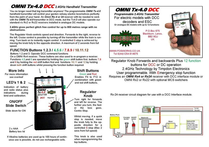
You no longer need that big transmitter anymore! The programmable OMNI Tx-3.1
Servo handheld transmitter will control your garden railway live steam locomotives
perfectly from the palm of your hand. An Omni Rx-3 or Rx23 receiver with be needed
to work with the OMNI Tx-3.1 transmitter.
2.4GHz gives perfect glitch free control for up to 800 metres range.
Four servos can be controlled from an OMNI Tx-3.1 Transmitter. Two infinitely varia-
ble and two with stop positions. Cruise control is possible by turning off the transmitter
while the train is running. Turn back on to instantly regain control.
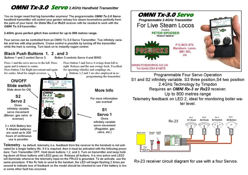
Black Push Buttons 1. 2 . and 3
Buttons 1 and 2 control Servo 3. Button 3 controls Servo 4 and BIND
Press button 3 and Servo 4 swings from left to
right. Release and the arm swings back. Excel-
lent for operating whistles and couplings etc.
Buttons 1,2 and 3 are also employed in re-
programming the transmitter
Press 1 and the servo moves to the left.
Press again and it returns to centre.
Press button 2 for Right movement
and again for centre. Very good for
Operating Forwards and reverse
Rx-23 receiver circuit diagram for use with a four Servos.
Programmable Four Servo Operation
S1 and S2 infinitely variable. S3 three position,S4 two position
Centre detent on S1 regulator control
2.4GHz Technology by Timpdon
Requires an OMNI Rx-3 or Rx23 receiver.
Up to 800 metres range
Telemetry feedback on LED 2
Ideal for use with older installed systems
OMNI Tx-3.1 Servo
2.4GHz Handheld Transmitter
2 x AAA
Battery box lid
ON/OFF
Slide switch
Slide down for ON
More Info
For more information
see overleaf
If Alkaline batteries are used up to 200 hours of continuous use is possible.
S2
Servo 2
For the first
infinitely variable
servo movement
(Blower or
reverser)
S1
Servo 1 or
ESC
For the second
infinitely variable
servo movement
or forwards and
reverse with ESC
(Regulator)
Centre Detent
Rx-23
OMNI Tx-3.1 Servo
Programmable 2.4GHz Transmitter
For Locos with ESC and
switcher units or servos
P.O.Box 675,
Blackburn, Lancs.
BB1 9DL
UK
WWW.FOSWORKS.CO.UK
Tel 0(44)1254 814675
Calibrating Servo start, mid and end positions.
Each servo can have it’s start and end settings adjusted independently.
The S1 servo knob is used to adjust all four servo settings.
The transmitter and receiver must be already bound together and tested.
It’s on video, if you prefer , see our website for the link.
The Calibration procedure must be carried out within 20 seconds of turning on the re-
ceiver, so start by ensuring everything is off, then power up the receiver.
1 Press and hold buttons 2 and 3, then turn Transmitter ON
2 Wait until both LEDS go solid, then release the buttons, you are now in calibration
mode and the only exit is to power off the transmitter.
3 LED 1 will be flashing the selected SERVO, use Button 1 to move to the next one.
4LED 2 will be indicating which servo position you wish to set, use button 2 to move to
the next one:
One flash = Start position of servo swing (When knob is fully anticlockwise)
Two flash = Mid position of servo swing (Not available on servos 1,2 and 4)
Three flash = End position of servo swing (when knob is fully clockwise)
5 Having selected the servo and the position you wish to set, use the S1 knob to set
the actual position of the servo arm and then save the position by pressing button 3.
6You can now go on to set more positions or leave the process by turning off the trans-
mitter, then back on again to check the results of your efforts.
Re-Programming Servo 3 and 4 to momentary or latching mode
Servo 3, when set to latching, toggles between mid and end positions on buttons 1 and
2, when set to momentary, will move from mid to start on button 1 and mid to end on
button 2, then back to the middle again.
Servo 4, when set to latching, toggles position from one end to the other on each press
of button 3 and when set to momentary moves from start to end position and back
again.
The Calibration procedure must be carried out within 20 seconds of turning on the re-
ceiver, so start by ensuring everything is off, then power up the receiver.
1 Press and hold buttons 1 and 2, then turn Transmitter ON
2Wait until both LEDS go solid, then release the buttons, you are now in calibration
mode and the only exit is to power off the transmitter.
3LED2 now indicates which servo is being set, one flash for SERVO 3 and 2 flashes
for SERVO 4. Use button 2 to move to the next one.
4Set the S1 (Regulator) knob to fully Anticlockwise for Momentary or fully Clockwise
for latching mode.
5Press button 3 to save this setting.
6Proceed with further settings OR power off the transmitter to leave the procedure.
For further advice, contact us by email at: [email protected] or call us
on 01254 814675
Re-programming the OMNI system to suit your needs.
Your OMNI transmitter and receiver comes to you all pre-set and ready to run
Live Steam Locomotives. Each servo is set for a full 90 degree swing. Normally
there should be no need to change these settings, However should the swing of
a servo need to be modified, it can be done by reprogramming the receiver.
The OMNI R/C system is unique, in that when you wish to re-program it to suit
the special needs for a particular loco, it is not the transmitter you are re-
programming, but the receiver in the loco. The Transmitter tells the receiver what
is expected of it in the future, and it is the receiver that remembers it. In this way,
one OMNI Tx-3.0 STEAM transmitter can control many different types of Live
Steam locos, each with its own very different requirements.
It is possible to change all or just one of the servo movements. The start and stop
position of each servo swing is adjustable. You can even reverse the servo
swings by setting the 1st position as the end and the 2nd position as the start.
Binding Procedure.
Now simpler than ever!
1. Turn on the Receiver (or the model, if it’s al-
ready fitted inside) then….
2. Hold down black buttons 1 and 3, then turn on
the transmitter
3. Successful binding is indicated by LED 2 going
fully ON.
4. Release the two buttons and the job is done. .
13
LED 1
On
LED 2
Low battery warning
When the batteries in the handset get too low for reliable operation, both LED 1 and
2 start flashing together. Replace them with quality alkaline AAA cells for the best
results,

Other Omni Transmitter manuals

Omni Tx-5.10 DCC User manual

Omni

Omni Tx-5.10 DCC User manual

Omni Tx-3.0 Servo User manual

Omni

Omni Tx-3.0 Servo User manual

Omni Tx-4.0 DCC User manual

Omni

Omni Tx-4.0 DCC User manual

Popular Transmitter manuals by other brands

Acromag microBlox Series user manual

Acromag

Acromag microBlox Series user manual

Camille Bauer SINEAX B 812 operating instructions

Camille Bauer

Camille Bauer SINEAX B 812 operating instructions

Emerson Rosemount OCX 8800 Reference manual

Emerson

Emerson Rosemount OCX 8800 Reference manual

Endress+Hauser iTEMP TMT182 operating instructions

Endress+Hauser

Endress+Hauser iTEMP TMT182 operating instructions

Emerson Rosemount 326T quick start guide

Emerson

Emerson Rosemount 326T quick start guide

Converters.TV 948 Operation manual

Converters.TV

Converters.TV 948 Operation manual

Endress+Hauser cerabar S PROFIBUS-PA operating instructions

Endress+Hauser

Endress+Hauser cerabar S PROFIBUS-PA operating instructions

Technalogix TAVD-40 Operation manual

Technalogix

Technalogix TAVD-40 Operation manual

Everlz 7707AT-A manual

Everlz

Everlz 7707AT-A manual

R.V.R. Electronica TX500SS user manual

R.V.R. Electronica

R.V.R. Electronica TX500SS user manual

GF Signet 8850-3 manual

GF

GF Signet 8850-3 manual

DMP Electronics 1142 Series installation guide

DMP Electronics

DMP Electronics 1142 Series installation guide

Origin Instruments Beam user manual

Origin Instruments

Origin Instruments Beam user manual

Extron electronics DTP2 T/R 211 user guide

Extron electronics

Extron electronics DTP2 T/R 211 user guide

PR electronics 6331 Series manual

PR electronics

PR electronics 6331 Series manual

Monarch 295SEPC1K manual

Monarch

Monarch 295SEPC1K manual

THORLABS MX10C user guide

THORLABS

THORLABS MX10C user guide

Smart-Fly Ignition Cutoff user guide

Smart-Fly

Smart-Fly Ignition Cutoff user guide

manuals.online logo
manuals.online logoBrands
  • About & Mission
  • Contact us
  • Privacy Policy
  • Terms and Conditions

Copyright 2025 Manuals.Online. All Rights Reserved.