manuals.online logo
Brands
  1. Home
  2. •
  3. Brands
  4. •
  5. Camille Bauer
  6. •
  7. Transmitter
  8. •
  9. Camille Bauer SINEAX B 812 User manual

Camille Bauer SINEAX B 812 User manual

14
Operating Instructions
Transmitter
Power Supply Unit
SINEAX B 812
B 812 Be 152 025-01 11.05
Camille Bauer LTD
Aargauerstrasse 7
CH-5610 Wohlen/Switzerland
Phone +41 56 618 21 11
Fax +41 56 618 35 35
e-mail: info@camillebauer.com
http://www.camillebauer.ch
Contents
1. Safety instructions ......................................................................... 1
1.1 Symbols ............................................................................... 1
1.2 Proper use ........................................................................... 1
1.3 Qualifications of the personnel ............................................ 1
1.4 Repairs and modifications ................................................... 1
2. Short description ........................................................................... 1
3. Indicator LEDs ............................................................................... 1
4. Installation instructions .................................................................. 2
5. Mounting the device ...................................................................... 2
6. Removal of the device ................................................................... 2
7. Dimension drawings ...................................................................... 2
8. Electrical connections ................................................................... 2
8.1 Connection without HART® terminal .................................... 2
8.2 Connection with HART® terminal ......................................... 2
9. Commissioning .............................................................................. 3
10. Technical data ............................................................................... 3
10.1 Input ..................................................................................... 3
10.2 Intrinsically safe input (Ex version) ....................................... 3
10.3 Output .................................................................................. 3
10.4 Accuracy .............................................................................. 3
10.5 Power supply ....................................................................... 3
10.6 Transfer ................................................................................ 3
10.7 Galvanic isolation ................................................................. 3
10.8 Ambient conditions .............................................................. 3
10.9 Various ................................................................................. 3
11. Versions ......................................................................................... 4
12. Maintenance .................................................................................. 4
13. Declaration of conformity .............................................................. 4
1. Safety instructions
1.1 Symbols
The symbols used in this operating instruction indicate dangers and
they have the following meanings:
Non-compliance could result in functional failures.
Non-compliance could result in functional failures and
injury to personnel.
1.2 Proper use
● The device is a transducer power supply for the safe isolation of
4…20 mA signal circuits.
● The device is intended for mounting in industrial installations and
fulfils the requirements according to EN 61010-1.
● The manufacturer is not liable for damage that is caused by improper
handling, modifications, or improper use.
● Optional with intrinsically safe input (blue terminals).
This is an “associated apparatus” and must not be installed in
explosion hazardous areas. The output is not intrinsically safe.
1.3 Qualifications of the personnel
Mounting, installation, and commissioning must only be carried out by
properly trained and authorized personnel, who have read and understood
these operating instructions.
1.4 Repairs and modifications
Repairs and modifications must only be carried out at our factory. The
housing must not be opened. There are no configuration or adjusting
elements inside the housing.
We reserve the right to make changes to improve the product.
2. Short description
The device supplies the passive 2-wire transducer (4…20 mA) which
is connected to the input with a DC voltage, and transmits the signal
current galvanically isolated 1:1 to the output. The current in the output
circuit is also supplied by the device. Therefore a passive signal receiver
(4…20 mA) must be connected.
The device is transparent for HART® signals in both directions. The
250 Ω resistor integrated in the output circuit permits communication
with SMART transmitters.
Open circuit and short circuit in the input circuit are indicated locally by
a red LED.
The device is single channel execution and is suitable for mounting on
a top-hat rail.
3. Indicator LEDs
There are two LEDs on the front of the device, which have the following
meaning:
Marking Color Meaning
ON Green The LED is on when
the power supply is on
Red
The LED is on when
the signal is outside
the normal measuring
range of 4…20 mA
Fig. 1
12. Maintenance
The device is maintenance free. Recalibration of the measured signal
is not possible.
13. Declaration of conformity
11. Versions
Device Ex-versions [EEx ia] IIC
Power supply Connection terminals Order number
60 – 253 V AC / 125 V DC not plugable 155 102
60 – 253 V AC / 125 V DC plugable 155 144
20 – 70 V AC/DC not plugable 155 095
20 – 70 V AC/DC plugable 155 136
Device standard versions
Power supply Connection terminals Order number
60 – 265 V AC/DC not plugable 155 087
60 – 265 V AC/DC plugable 155 128
20 – 70 V AC/DC not plugable 155 079
20 – 70 V AC/DC plugable 155 110
The instruments must only be disposed of in the
correct way!
32
4. Installation instructions
The maximum ambient temperature must be obser-
ved.
There must be sufficient circulation of air.
Neighboring devices that produce heat must be mounted
at a suitable distance.
The preferred mounting method is on a horizontal rail.
The device must be protected from vibrations.
8. Electrical connections
● Terminals without internal connections (1, 2, 3, 6
and 12) must remain free and must not be used for
other purposes.
● Ex devices may only be operated with a DC power
supply of upto Um = 125 V DC.
5. Mounting the device
The SINEAX B 812 device is mounted on a top-hat rail.
Snap the device housing onto the top-hat rail (EN 50 022) (see Fig. 2).
Fig. 2. Mounting on a top-hat rail 35 ×15 or 35×7.5 mm.
6. Removal of the device
Remove the device from the top-hat rail as shown in Fig. 3.
Fig. 3
7. Dimension drawings
Fig. 4. The SINEAX B 812 in a top-hat rail housing P12/17 mounted on a top-hat
rail (35 × 15 mm or 35 × 7.5 mm to EN 50 022) with fixed connection screw
terminals.
63
69.2
17.5 114
Fig. 5. The SINEAX B 812 in a top-hat rail housing P12/17 St mounted on a top-hat
rail (35 × 15 mm or 35 × 7.5 mm to EN 50 022) with plug-in connection screw
terminals.
63
85
17.5 114
5
4
10 11
9
8
7
Two-wire
transmitter
B 812
DC
AC
–
N
+
L
Signal
receiver
+
–
+
–
8.2 Connection with HART® terminal
5
4
10 11
9
8
7
Two-wire
transmitter
B 812
DC
AC
–
N
+
L
Signal
receiver
HART®-
Terminal
+
–
+
–
For the correct functioning of the communication, a
250 Ω communication resistor is required in series with the
measuring circuit. Please observe that the maximum load
on the B 812 output resulting from additional devices and
the resistance of the wires is not exceeded.
Internal communication resistor
External communication resistor
5
4
10 11
9
8
7
B 812
DC
AC
–
N
+
L
HART®-
Terminal
250 �
Ω
+
–
+
–
Two-wire
transmitter
Signal
receiver
9. Commissioning
The installation and wiring must be checked before commissioning, and
in particular the permitted power supply voltage must be checked (see
the rating label).
10. Technical data
10.1 Input
Signal range 4…20 mA
Power supply voltage (I = 20 mA) 18.0 V ± 1 V
No-load voltage (I = 0 mA) 25.5 V ± 1 V
Short circuit current limitation 25 mA ± 2 mA
Source resistance 330 Ω ± 5 Ω
Open circuit detection 3.5 mA ± 0.1 mA
Short circuit detection 21.2 mA ± 0.2 mA
10.2 Intrinsically safe input (Ex version)
Provisional data
Uo28,2 V
Io95 mA
Po0.67 W
Type of protection [EEx ia] IIC
Marking II (1) GD
10.4 Accuracy
Reference conditions
Tamb = 23°C, load = 300 Ω
Warm up time 20 minutes
Power supply = 24 V DC or
230 V AC
Range = 16 mA 100%
Error tolerance incl. linearity error
under reference conditions ± 0.2%
Effect of output load < 0.1%
Temperature effect < 0.1% / 10°K
Effect of power supply < 0.05%
10.5 Power supply
Universal power supply for DC and AC
Low-range
version
High-range
version
Voltage range AC/DC
(absolute limits) 20 – 70 V 60 – 265 V *)
Switching-on current Î / τ2.5 Â / 1.0 ms
at 24 V DC
20 Â / 0.15 ms
at 325 V DC
Frequency range AC 45 … 400 Hz
Power consumption max. 3 VA / 2.4 W
*) Voltages > 125 V DC require external protection with max. 10 A trip
current. For the Ex version, the data in the EC type examination certi-
ficate are valid (Um = 253 V AC or 125 V DC).
10.6 Transfer
Signal current over-range 10 %
Response time < 0.3 ms
HART®Transparent for HART®
signals in both directions
10.3 Output
Signal range 4…20 mA
No load voltage (I = 0 mA) 17.0 V ± 1 V
Internal
communication resistor Rc 250 Ω
Permitted load 0…750 Ω
0…500 Ω (via Rc)
10.7 Galvanic isolation
All three circuits (input / power supply / output) are galvanically isolated
from each other.
Electrical safety
To IEC / EN 61010-1
Double isolation
Measuring and overvoltage
category III
Contamination level 2
Working voltage < 300 V
Test voltage 3.6 kV / 50 Hz / 1 minute
10.8 Ambient conditions
Operating temperature – 20 … +50 °C
Storage temperature – 20 … +70 °C
Rel. humidity avarage ≤ 75%
Protection type IP 20, EN 60 523
EMV EN 61 000-6-2 / -4
10.9 Various
Weight 100 g
Terminal cross section 2.5 mm2
Plug-in terminals (alternative) Coded to prevent
incorrect connection
1 2 3
4 5 6
7 8 9
10 11 12
Fig. 6. Arrangement of the terminals
8.1 Connection without HART® terminal

Other Camille Bauer Transmitter manuals

Camille Bauer KINAX WT720 User manual

Camille Bauer

Camille Bauer KINAX WT720 User manual

Camille Bauer KINAX 2W2 User manual

Camille Bauer

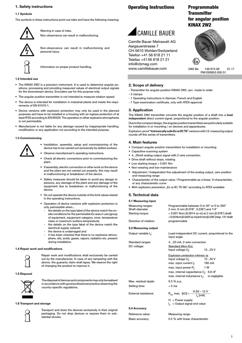
Camille Bauer KINAX 2W2 User manual

Camille Bauer KINAX WT720 User manual

Camille Bauer

Camille Bauer KINAX WT720 User manual

Camille Bauer KINAX 3W2 User manual

Camille Bauer

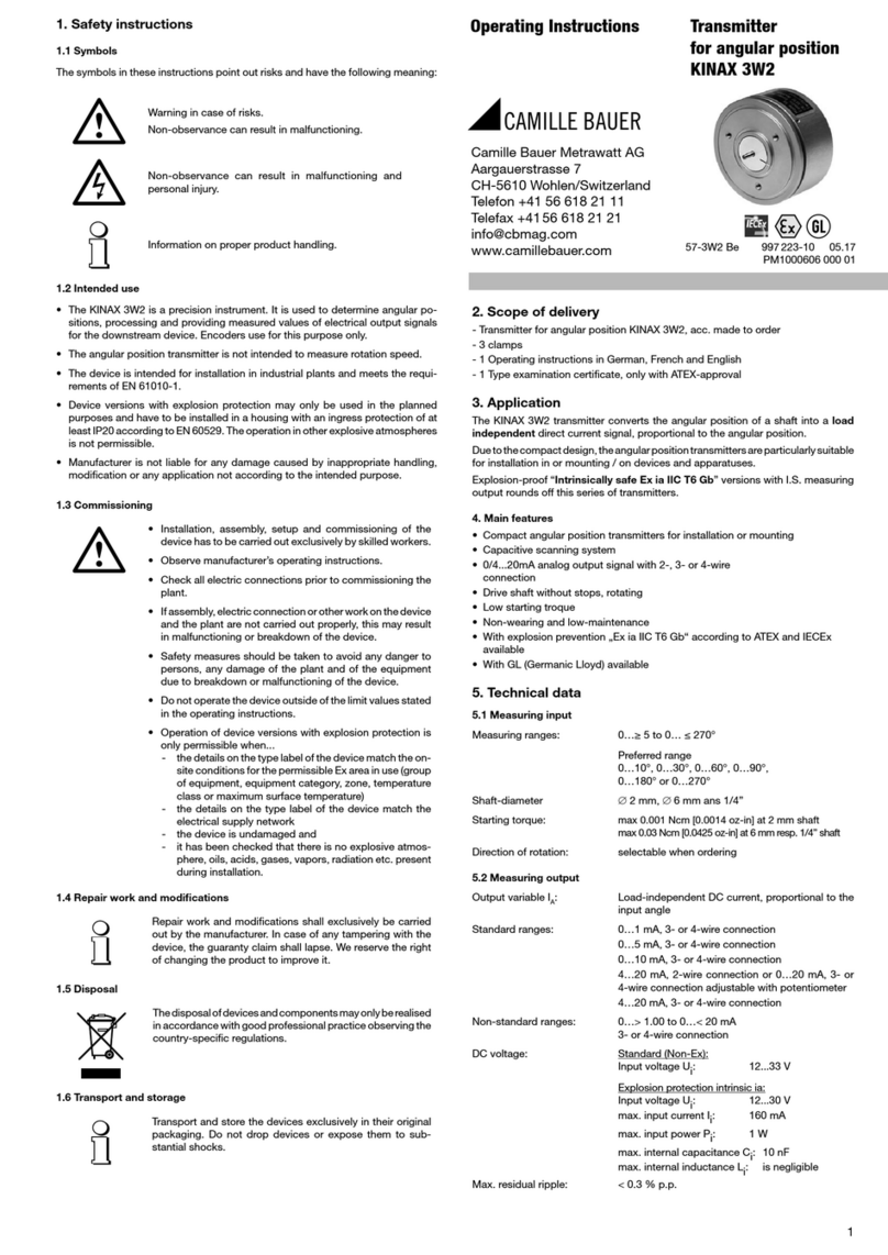
Camille Bauer KINAX 3W2 User manual

Camille Bauer KINAX WT 717 User manual

Camille Bauer

Camille Bauer KINAX WT 717 User manual

Camille Bauer KINAX N702-INOX HART User manual

Camille Bauer

Camille Bauer KINAX N702-INOX HART User manual

Camille Bauer KINAX N705-MEMS User manual

Camille Bauer

Camille Bauer KINAX N705-MEMS User manual

Camille Bauer SINEAX V604s User manual

Camille Bauer

Camille Bauer SINEAX V604s User manual

Camille Bauer KINAX 2W2 User manual

Camille Bauer

Camille Bauer KINAX 2W2 User manual

Camille Bauer KINAX WT 707-SSI User manual

Camille Bauer

Camille Bauer KINAX WT 707-SSI User manual

Camille Bauer KINAX HW730 User manual

Camille Bauer

Camille Bauer KINAX HW730 User manual

Camille Bauer SINEAX V604 User manual

Camille Bauer

Camille Bauer SINEAX V604 User manual

Camille Bauer KINAX WT 717 User manual

Camille Bauer

Camille Bauer KINAX WT 717 User manual

Camille Bauer KINAX N705-MEMS User manual

Camille Bauer

Camille Bauer KINAX N705-MEMS User manual

Camille Bauer KINAX N702-SSI User manual

Camille Bauer

Camille Bauer KINAX N702-SSI User manual

Camille Bauer KINAX N702-INOX HART User manual

Camille Bauer

Camille Bauer KINAX N702-INOX HART User manual

Popular Transmitter manuals by other brands

Herutu TW-800R-SCL instruction manual

Herutu

Herutu TW-800R-SCL instruction manual

Spektrum DX5e quick start guide

Spektrum

Spektrum DX5e quick start guide

VideoComm Technologies TC-916 manual

VideoComm Technologies

VideoComm Technologies TC-916 manual

YOKOGAWA vigilantplant YTA Series user manual

YOKOGAWA

YOKOGAWA vigilantplant YTA Series user manual

LRS T7400A Setup guide

LRS

LRS T7400A Setup guide

CircuitWerkes CW Broadcast Gamma Operating manual and user guide

CircuitWerkes

CircuitWerkes CW Broadcast Gamma Operating manual and user guide

Nautel NV7.5 Operation and maintenance manual

Nautel

Nautel NV7.5 Operation and maintenance manual

AMC CU900 Installer manual

AMC

AMC CU900 Installer manual

Spektrum DX5R instruction manual

Spektrum

Spektrum DX5R instruction manual

Risco WL T72C installation instructions

Risco

Risco WL T72C installation instructions

Rosemount 2051CF Series quick start guide

Rosemount

Rosemount 2051CF Series quick start guide

Williams Sound Personal PA T46 user manual

Williams Sound

Williams Sound Personal PA T46 user manual

Sekonic RT-20PW operating manual

Sekonic

Sekonic RT-20PW operating manual

Master VECTOR 24 manual

Master

Master VECTOR 24 manual

Rose electronics UltraVista VWL-S122DV Installation and operation manual

Rose electronics

Rose electronics UltraVista VWL-S122DV Installation and operation manual

Tachosys digiPostpro Administration guide

Tachosys

Tachosys digiPostpro Administration guide

Novus TXMINI-M12-485 operating manual

Novus

Novus TXMINI-M12-485 operating manual

Tedsen SKJ22MR Operation manual

Tedsen

Tedsen SKJ22MR Operation manual

manuals.online logo
manuals.online logoBrands
  • About & Mission
  • Contact us
  • Privacy Policy
  • Terms and Conditions

Copyright 2025 Manuals.Online. All Rights Reserved.