manuals.online logo
Brands
  1. Home
  2. •
  3. Brands
  4. •
  5. Omni
  6. •
  7. Transmitter
  8. •
  9. Omni Tx-5.10 DCC User manual

Omni Tx-5.10 DCC User manual

OMNI Tx-5.10DCC
Programmable 2.4GHz Transmitter
For simultaneous control of up to
10 models and 24 functions on
each model.
P.O.Box 675,
Blackburn, Lancs.
BB2 9QJ
UK
WWW.FOSWORKS.CO.UK
Tel 01254 814675
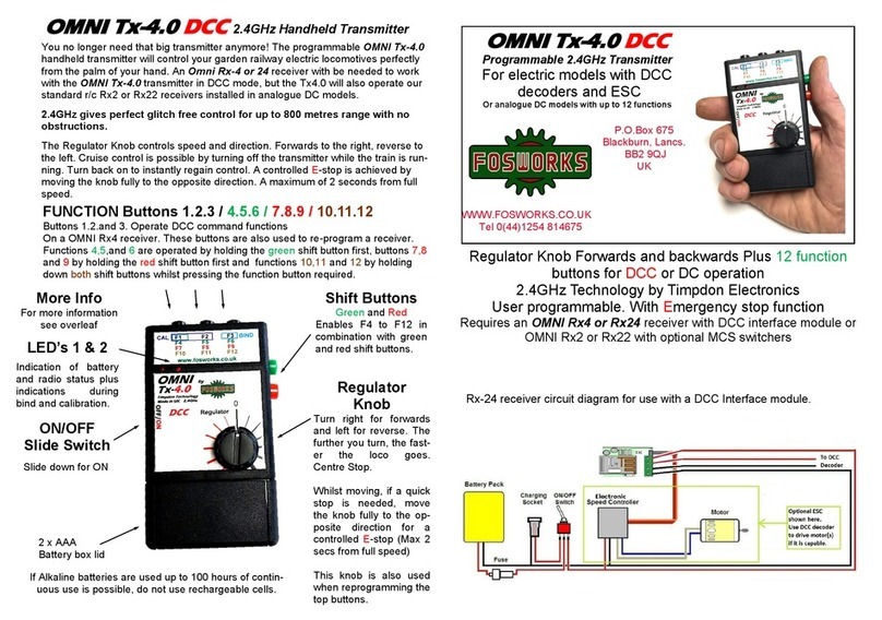
Rx-24 receiver circuit diagram showing optional use of ESC. Note that stand-
ard Rx24 do not have the ESC connection, Rx24-ESC must be ordered spe-
cially. There are several versions including Drivelock on F8.
The programmable OMNI Tx-5.10 handheld transmitter will control your garden railway
electric locomotives perfectly from the palm of your hand. An Omni FRx-24 receiver with
be needed to work with the OMNI Tx-5.10 transmitter in DCC mode, but the Tx5.10 will
also operate our standard r/c Rx22 receivers in analogue DC models.
2.4GHz gives glitch free control for up to 800 metres range with no
obstructions.
The Regulator Knob controls speed and direction. Forwards to the right, reverse to the
left. Cruise control is possible by turning off the transmitter while the train is running.
Turn back on to instantly regain control.
OMNI Tx-5.10 DCC
2.4GHz Handheld Transmitter
2 x AAA Battery box
FUNCTION 1.2.3 / 4.5.6 / 7.8.9 / 10.11.12
Buttons 13.14.15/16.17.18 /19.20.21/22.23.24
Buttons 1.2.and 3 in conjunction with RED and GREEN Operate DCC command functions
These buttons are also used to re-program a receiver.
Functions 4,5,and 6 are operated by holding the green shift button first, buttons 7,8 and 9
by holding the red shift button first and functions 10,11 and 12 by holding down both shift
buttons whilst pressing the function button required., likewise for functions 13 - 24.
ON/OFF
Slide Switch
Slide down for ON
If Alkaline batteries are used up to 100 hours of continuous
use is possible
10 way Selector
Knob
Use it in combination
with Channel switch to
move between models,
then press RED button
to acknowledge, once
you have checked
speed setting.
Regulator Knob Forwards and backwards with centre stop.
Toggle switch allows function range to be selected and the se-
lector knob allows simultaneous control of up to 10 models.
24 functions for DCC operation
2.4GHz Technology by Timpdon Electronics
With Emergency stop function
Requires an OMNI Rx24 receiver with DCC interface module or OMNI
Rx22 or Rx2 with optional MCS switchers for analogue DC operation
Shift Buttons
Green and Red
Enable F4 to F12 in com-
bination with black but-
tons. E.g. F7 is obtained
by pressing and holding
the RED button then
pressing BLACK button
F1. Hold both down to
obtain F10, F11 and F12.
LED’s 1 & 2
Indication of battery
and radio status plus
indications during bind
and calibration.
Regulator Knob
Turn right for forwards
and left for reverse. The
further you turn, the fast-
er the loco goes.
Centre Stop.
Whilst moving, if a quick
stop is needed, move the
knob fully to the opposite
direction for an E-stop
This stops ALL active
models.
This knob is also used
when reprogramming the
top buttons.
Selector
Switch to change be-
tween functions 1-12
and 13-24
Binding Procedure.
Now simpler than ever!
1. Turn on the Receiver (or the model, if it’s al
ready fitted inside) then….
2. Move Selector switch to position desired for the
model.
3. Hold down black buttons 1 and 3, then turn
on the transmitter
4. Successful binding is indicated by LED 2 going
ON.
5. Release the two buttons and the job is done. LED
1 goes solid to indicate that the transmitter and
receiver are linked.
13
Programming the OMNI system to suit your needs.
The OMNI R/C system is ideal, in that when you wish to re-program it to suit the spe-
cial needs for a particular loco, it is not the transmitter you are re-programming, but the
receiver in the loco. The Transmitter tells the receiver what is expected of it in the fu-
ture, and it is the receiver that remembers it. In this way, one OMNI transmitter can
control many different types of locos, each with its own very different requirements.
It is possible to change all or just one of the functions from Momentary to latching.
LED 1
On
Low battery warning
When the batteries in the handset get too low for reliable operation, both LED 1 and 2
start flashing together. Replace them with quality alkaline AAA cells for the best results,
LED 2
Re-Programming the top Buttons for momentary or
latching operation
(All are momentary by default, except F1 on Rx24 DCC re-
ceivers, which is latching by default)
This procedure must be started within 20 seconds of turning on the receiver, there-
fore start with the transmitter off and the model switched on. See our website for a
link to video instructions.
First you must put the transmitter into Button Calibration Mode :-
1. With the Transmitter turned Off. Press and hold button 1 and 2.
2. Turn the Transmitter On.
3. Both LED’s will start flashing, then go solid, indicating successful entry to
the Button Calibration mode. At this point, release the two buttons. LED 2 now
stays solid, whilst LED1 goes off.
Once in Button Calibration Mode, there is no exit except Transmitter power Off.
CHANGING BUTTONS FROM MOMENTARY TO LATCHING
The Regulator control knob is used to change the function of a button from latching
to Momentary or Vice Versa. Turn it in the desired direction and the given button
will be changed.
Fully anti-clockwise = Momentary Fully clockwise = Latched
Press the required buttons to save the setting for a function.
For example if you want function 12 to be latching, turn the regulator fully clockwise
and press both shift buttons followed by button 3.
You can now select another button to change, or turn the transmitter off.
Should you wish to reset the centre Off stop position, please contact me by email at
sales@fosworks.co.uk
If you do not have a computer, please call us on 01254 814675

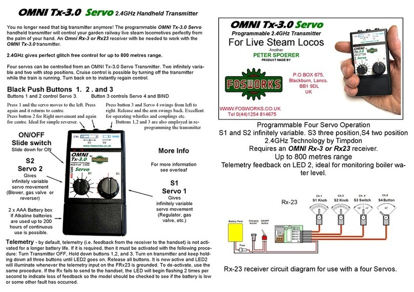
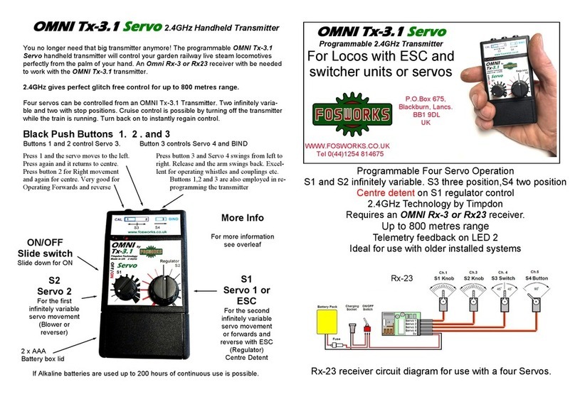
Other Omni Transmitter manuals

Omni Tx-3.0 Servo User manual

Omni

Omni Tx-3.0 Servo User manual

Omni Tx-3.1 User manual

Omni

Omni Tx-3.1 User manual

Omni Tx-4.0 DCC User manual

Omni

Omni Tx-4.0 DCC User manual

Popular Transmitter manuals by other brands

Tri-Tronics Pro Control RL owner's guide

Tri-Tronics

Tri-Tronics Pro Control RL owner's guide

Inovonics EN1210 installation instructions

Inovonics

Inovonics EN1210 installation instructions

Vaisala HMD82M Technical note

Vaisala

Vaisala HMD82M Technical note

Continental Automotive 5WK50079 user manual

Continental Automotive

Continental Automotive 5WK50079 user manual

WIKA S-10 operating instructions

WIKA

WIKA S-10 operating instructions

Nice DTX6 Instructions and warnings for installation and use

Nice

Nice DTX6 Instructions and warnings for installation and use

Greystone Energy Systems CDD4B1 Series installation instructions

Greystone Energy Systems

Greystone Energy Systems CDD4B1 Series installation instructions

King-Gage 5800 Series quick start guide

King-Gage

King-Gage 5800 Series quick start guide

Sentera Controls RSMFH-3 manual

Sentera Controls

Sentera Controls RSMFH-3 manual

CYP PU-107 Operation manual

CYP

CYP PU-107 Operation manual

WebGate WebEye A10 user guide

WebGate

WebGate WebEye A10 user guide

Kramer SID-X1N user manual

Kramer

Kramer SID-X1N user manual

FISCHER DE85 operating manual

FISCHER

FISCHER DE85 operating manual

Endress+Hauser Liquisys M CLM223F operating instructions

Endress+Hauser

Endress+Hauser Liquisys M CLM223F operating instructions

TFA WeatherHub 30.3301.02 quick reference

TFA

TFA WeatherHub 30.3301.02 quick reference

AlzaPower APW-FMTV1 user manual

AlzaPower

AlzaPower APW-FMTV1 user manual

krispol STARCUS ONE W operating instructions

krispol

krispol STARCUS ONE W operating instructions

Imperii Electronics multi-point instructions

Imperii Electronics

Imperii Electronics multi-point instructions

manuals.online logo
manuals.online logoBrands
  • About & Mission
  • Contact us
  • Privacy Policy
  • Terms and Conditions

Copyright 2025 Manuals.Online. All Rights Reserved.