Philadelphia Solar PS-M72 Series Quick start guide

Installation &

QP-10-IM21UL/Rev 12
This manual contains important safety instructions for the PV module that must be
followed during
the maintenance of PV modules. To reduce the risk of electric shock, do not perform any
servicing unless you are qualified to do so.
“PV equipment on the DC side shall be considered to be energized, even when the
system is disconnected from AC side and isolated from PV Inverter”, “PV modules will
be producing dangerous levels of voltages and current».
1. The installation must be performed by a certified installer/servicer.
2. The installation is only allowed after referring and understanding of Installation on
manual.
3. Installation and commissioning shall be done in accordance with IEC 62446 &
IEC60346 and their associated codes.
4. Do not pull the PV cables.
5. Protect PV Modules cables from direct sunlight.
6. Do not strain junction box conductors.
7. Do not touch any surface ofmodule.
8. Do not place/drop objects onto the PV module.
9. Do not disassemble or attempt to repair the PV module by yourself.
10. Do not damage, pull, bend or place heavy material on c ab l e s .
11. Do not use stainless wire ties or any othersharp material to tight the PV Modules
cables directly.
12. Protect PV Cables from Pests and small animals is essential.
13. Upon completion of any service or repairs, ask the installer /servicer to perform
routine checks to determine that the PV modules are in safe and proper operating
condition.
14. When replacement parts are required, be sure the installer /servicer uses parts
specified by the manufacturer with same characteristics as the original parts
unauthorized substitutions may result in fire, electric shock or another hazard.
15.Consult your local building and safety department for required permits and
applicable regulations.

QP-10-IM21UL/Rev 12
GENERAL INSTRUCTIONS:
This installation manual contains essential information for the electrical and mechanical
installation that you must know before installation modules. This also Contains safety
information you need to be familiar with. All information described in this manual are
intellectual property and based on technologies and experiences that have been
acquired and accumulated throughout years even it is short period, but it is enough to
prepare such comprehensive report about installation. This document does not
constitute a guarantee, expressed or implied.
Philadelphia Solar does not assume responsibility and expressly disclaims liability for
loss, damage, or expanse arising out of or in any way connected with installation,
operation, use or maintenance of PV modules. No responsibility is assumed by
Philadelphia Solar for any infringement of patents or other rights of third parties that may
results from use of PV module. Philadelphia Solar reserves the right to make changes to
the product, specifications or installation manual without prior notice.
GENERAL INFORMATION
The installation of PV modules requires a great degree of skill and should only be
performed by a qualified licensed professional, including licensed contractors and
licensed electrifications. Please be aware that there is a serious risk of various types of
injury occurring during the installation including the risk of electric shock. All modules are
equipped with a permanently attached Junction box that will accept variety of wiring
applications or with a special cable assembly for ease of installation, and they do not
require special assembly.
GENERAL WARNING
1. PV modules are heavy. Handle with care.
2. Before you attempt to install, wire, operate and maintain the PV module, please
make sure that you completely understand the information described in this installation
manual.
3. Contact with electrically active parts of a PV module such as terminals can result
in burns, sparks, and lethal shock whether the PV modules is connected or not.
4. PV modules produce electricity when the enough sunlight or other sources
illuminate the module surface.

QP-10-IM21UL/Rev 12
5. Use a single safety locking clip MC4 style connector for connecting solar
cables.
6. Follow the connector manufacturer’s assembly instructions when preparing and
assembling connectors in the field. Use the manufacturer-
7. -specified crimp tool and ensure that it is set appropriately for the conductor gauge
and type, Conductors slipping out of connector fittings are a common cause of arc
faults.
8. When the modules are connected in series, voltage is cumulative. When the
modules are connected in parallel current is cumulative. As a result, a large –scale PV
system can produce high voltage and current which could present an increased hazard
and may cause serious injury or death
9. Do not connect PV modules directly to the loads such as motor since the variation of
the output power depending on the solar irradiation causes damage for the connected
motor.
In case of a brushless motor, the lock function becomes active and the hall IC is most
likely to be damaged.
In the case of a brush type motor, the coil is most likely to be damaged.
GERNERAL SAFETY
•
Consult local codes and other applicable laws concerning required permits on
regulations concerning installation and inspection requirements.
•
Before installing a PV module, contact appropriate authorities to determine permit,
installation and inspection requirements that should be followed.
•
Install PV modules and ground frame in accordance with applicable rules and
regulations.
•
PV modules should be installed and maintained by qualified personnel. Only
installer/service personnel should have access to the PV modules installation site.
•
No matter where the PV modules are installed either roof mounted construction or any
other types of structures above the ground, appropriate safety practices should be
followed and required safety equipment should be used in order to avoid possible safety
hazards. Note that the installation of some PV modules on roofs may require the addition
of fire proofing, depending on local building/ fire codes.
•
In case that PV modules are non-integral type, the modules must be mounted over a fire-
resistant roof.

QP-10-IM21UL/Rev 12
•
Please use PV modules with same cell size within series.
•
Follow all safety precautions of other components used in the system.
•
In order to avoid a risk of injury or electrical shock, do not allow anyone to approach the
PV module if the person has little knowledge on PV module or on the measures that should
be taken when PV modules are damaged.
•
Do not shade portions of the PV modules surface from the sunlight for a long time. The
shaded cell may become hot (hot spot phenomenon) which results in solder joints peeling
off.
•
Do not clean the glass surface with chemicals. Do not let water stay on the glass surface
of PV modules for a long time. This creates a risk of white efflorescence (glass disease)
which may result in the deterioration of energy generation.
•
Purity degree of washing water shall be considered to avoid any chemical reaction with
PV Modules glass cover.
•
Do not install the PV module horizontally. it may cause
dirt or white efflorescence (glass
disease) due to water
•
Do not cover the water drain holes of the frame. There is a risk of frost damage when the
frame is filled with water accumulation.
•
When sliding snow load has to be considered, an appropriate measure has to be taken
so that PV module frames on lower edge of PV modules will not be damaged.
•
Do not expose PV module to concentrated sunlight with mirrors, lenses or similar means.
•
Turn off inverters and circuit breakers immediately, if any problem occurred.
•
In case the glass surface of a PV module is broken, wear goggles, gloves and tape the
glass to keep the broken pieces in place.
•
A defective PV module may generate power even if it is removed from the system. It may
be dangerous to handle the PV while exposed to sunlight. Place a defective PV module
in a carton so PV cells are completely shaded.
•
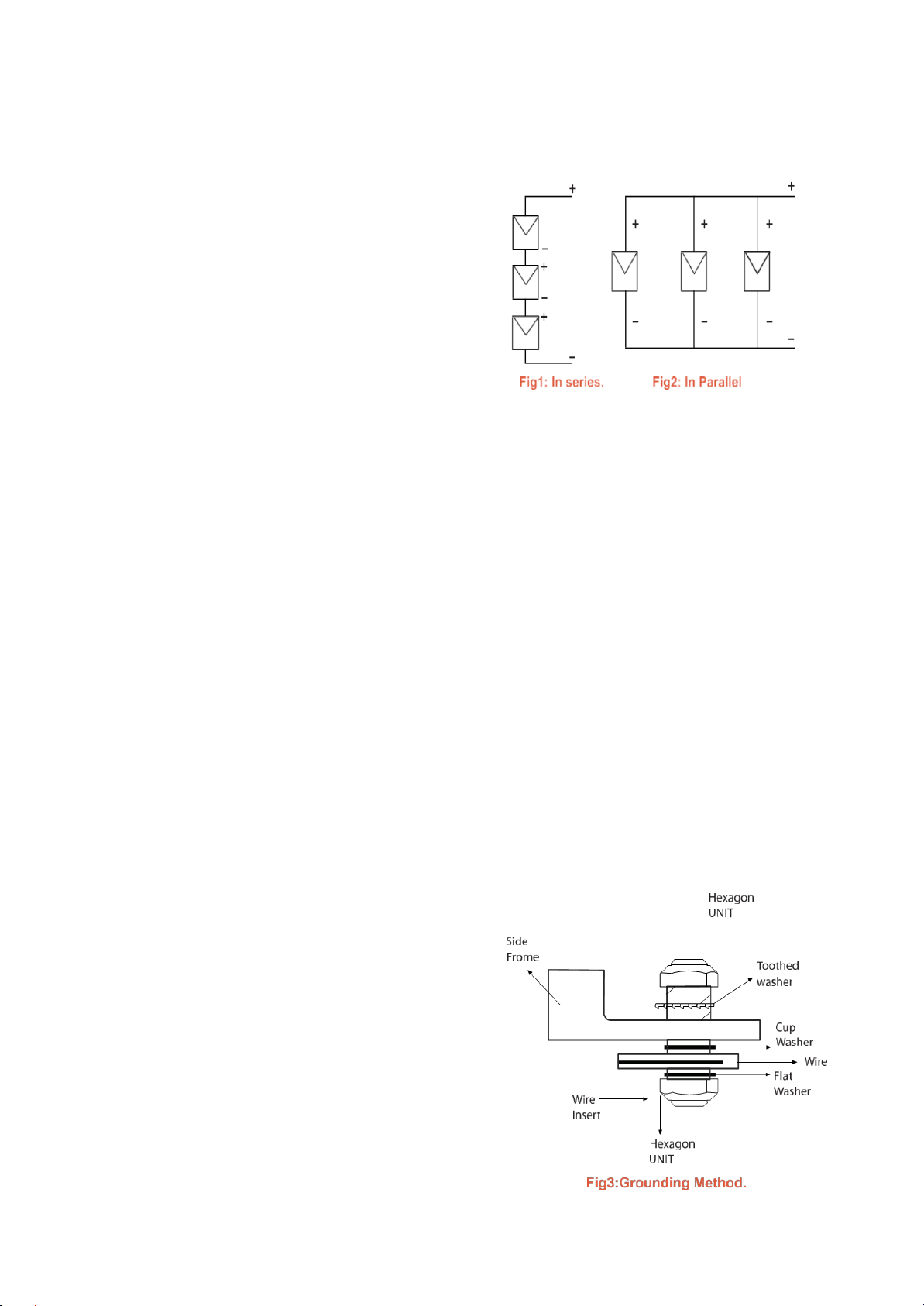
In case of series connection, Number of Series Modules shall be determined according to
the minimum design temperature for installation location and not to exceed
1000Vdc/1500Vdc for the string of series PV Modules at any time. The maximum open
circuit voltage must not be greater than the specified maximum system voltage as per
below equation:
•
In case of series connection, Number of Series
•
Max System Voltage ≥ N * Voc * [1 + TCvoc x (Tmin-25)].
•
Where N refers to number of modules, TCvoc: Thermal Coefficient of open circuit voltage

QP-10-IM21UL/Rev 12
for the module as per data sheet. And Tmin: refer to the lowest ambient Temperature.
•
The voltage is proportional to the number of series. In case of parallel connection please
be sure to take proper measure (e.g. fuse for protection of module and cable form over
current, and /or blocking diode for prevention of unbalanced strings voltage) to block
the reverse current flow. The current may easily flow in a reverse direction.
•
If more than 2 PV Modules or sting of Modules connected in parallel a PV Fuse with a
rating of 15A shall be used for both negative and positive side and in accordance with
IEC 62446 & IEC60346 and their associated codes.
•
Be careful! Always check the module label to confirm the actual rating of your product
before making connections whether it is 1000Vdc or 1500Vdc.
•
It is recommended to use a suitably rated isolator (DC switch) to interrupt the current flow
before disconnecting the connectors.
HANDLING SAFETY
•Do not cause an excessive load on the surface of PV module or twist the frame. The glass
surface can easily break.
•Do not stand or step on the PV module. The glass surface of PV is slippery and that would
cause microcracks in cells which affect the power generation.
•Do not hit or put excessive load on the glass or in the Backsheet, it is vulnerable.
•Do not hit the terminal box or do not pull the cables. The terminal box can crack and
break.
•Never touch the terminal box or the end of output cables with bare hands when the PV
module is irradiated. Cover the surface of PV module with clothes or other suitable
sufficiently opaque material to isolate the PV module from incident light and handle the
wires with rubber-gloved hands to avoid electric shock.
•To make positive electrical contact with the frame. The ground wire must be considered
within the requirement of local and regulation at the site of installation.
•The ground wire cross-sectional area (4-14) mm2, the minimum size of ground wire (6-12)
AWG (solid bare copper) per Table 250.122 of NEC code. Conductor Type: Copper
Material-Color of wire: Green color with yellow stripe. • Do not drill holes in the frame. It
may compromise the frame strength and cause corrosion of the frame.
•Do not scratch the insulation coating of the frame (except for grounding connection. it
may cause corrosion of the frame or compromise the framework strength.

QP-10-IM21UL/Rev 12
•Do not loosen or remove the screws of the PV module. It may compromise the joint
strength of PV module and cause corrosion.
•Do not touch the PV module with bare hands. The frame of PV module has sharp
edges and may cause injury.
•Do not drop PV module or allow objects to fall on the PV module.
•Do not try artificially to concentrate sunlighton the PV module.
•Do not grab the PV module at one side only. The frame may bend. Grab the PV
module at two sides facing each other.
INSTALLATION SAFETY
•Always wear protective head gear, insulating gloves and safety shoes (with rubber
soles).
•Keep the PV module packed until installation.
•Do not touch the PV module unnecessarily during installation. The glass surface and
the frames get hot. There is a risk of burn, or you may collapse because of electric
shock.
•Do not work under rain, snow or windy conditions.
•Use insulated tools.
•Do not use wet tools.
•Do not drop tools or hard objects onPVmodules.
•When installing PV modules far above ground do not drop any object (e.g. PV module
or any tool).
•Make sure flammable gases are not generated near the installation site.
•Completely cover the PV module surface with an opaque material during PV module
installation and wiring.
•Plug in the connector tight and ensure the
•wiring work.
•Due to the risk of electrical shock do not perform any work if the terminals of PVmodule
are wet.
•Do not touch the terminal box and the end of output cables the cable ends
(connectors) with bare hands during installation or under sunlight, regardless of
whether the PV module is connected to or disconnected to aload.
•Do not stomp on the glass at work. There is a risk of injury or electric shock if glass is
broken.

QP-10-IM21UL/Rev 12
•Do not work alone and work as a team.
•Wear a safety belt if working far above the ground.
•Do not wear metallic jewelry which can cause electric shock during installation.
•Do not damage the back sheet of PV modules when fastening the PV modules to a
support by bolts.
•Do not damage the surrounding PV modules or mounting structure when replacing
a PV module.
•Bind cables by the installation locks. Drooping down of cables from the terminal box
could possibly cause various problems such as animal biting, electricity leakage in
puddle.
•Take proper measures for preventing the laminate (consisted of resin, cells, and
glass, back sheet …etc.) from dropping out of the frame in case the glass is broken.
•Cables shall be located so that they will not be exposed to direct sunlight after
installation to prevent degradation of cables.
SITE SELECTION:
In most applications, the PV modules should be installed in a location where there is
no shading throughout the year. The PV panels face south In the Northern
Hemisphere.
Please make sure that there are no obstructions in the surroundings of the site of
installation. Take proper steps in order to maintain reliability and safety, in case the
PV modules are used in areas such as: Heavy snow areas/Extremely cold
areas/strong wind areas/installation over, or near, water/Areas where installations
are prone to saltwater damage/small islands or desert areas.
Lightning protection is recommended for PV systems that are to be installed in
locations with high probability of lightning strikes.
For Bifacial Modules:
•The energy output of bifacial module can be affected by albedo of the ground
that module installed on, height of module, Ground coverage Ratio (GCR), and

QP-10-IM21UL/Rev 12
Diffused horizontal irradiance
•Installation height of bifacial module
is recommended to be higher than 1
meter in order to harvest maximum
available reflected and diffused
radiation and to reduce shading on the
backside.
•Structure, cables and any other
component of installation should not
cause shading on the backside of the
modules.
TILT ANGLE:
The tilt angle of the PV module is the measured between the PV module and a
horizontal ground surface. The PV module generates the maximum output power
when it faces the sun directly. 5 degrees or more is recommended for the tilt angle of
the PV module for the maintenance.
For the stand alone systems with a battery where the PV modules are attached to a
permanent structure, the tilt angle of the PV modules should be determined to
optimize the performance when the sunlight is the scarcest, In general, if the electric
power generation is adequate when the sunlight is the scarcest, then the angle
chosen should be adequate during the rest of the year. For Grid-connected
installations where the PV modules are attached to a permanent structure, it is
recommended to tilt the PV module at the angle equal to the latitude of the
installation site so that the power generation from the PV module will be optimum
throughout the year.
Artificially concentrated sunlight shall not be directed to the panel, or module.

QP-10-IM21UL/Rev 12
WIRING:
To ensure proper system operation and to
maintain your guarantee, observe the correct
cable connection polarity (Fig 2 &1) when
connecting the modules to a battery or to
other modules. If not connected correctly, the
bypass diode could be destroyed.
PV module scan be wired in series to increase
voltage. Connect wires from the positive
terminal of one module to the negative terminal of the next module. Fig 1: Shows
modules connected in series.
Connect PV modules in parallel to increase current. Connect wires from the Positive
terminal of one module to the positive terminal of the next module. Fig2: Shows
modules connected in parallel.
GROUNDING /Earthling & Insulation for DC cables according to
IEC712-7-60364:
The frame grounding must consider the local requirements and regulations at the
site of installation. When grounding is required please refer to the below example
connection (Fig3). Please be careful in arranging the system ground so that the
removal of one module from the circuit will not interrupt the grounding of any other
modules.
The modules should be grounded to the same electrical point as described below.
Each PV module has a hole on the side frame
for a bolt, nut and washer grounding the
module to the frame, a ground lug fastened
by bolt or screw or appropriate screw. Near
the hole for ground you will find an etching
mark is indicated as ground symbol.
An example of accepted ground method is
described below in Fig: 3 using bolt, nut and
washer retaining a ground lug. In a
connection of this type, the hardware (such

QP-10-IM21UL/Rev 12
as toothed locked washer/Star washer) must score the frame surface The hardware
components (Toothed washer, cup washer, flat washer and hexagon unit) as
mentioned in the drawing below must be fit to 4mm hole. Torque Value: < (2.82 –7)
N-m, (2.07-5.2) ft- lbs. > on 4 mm size bolt and nut necessary to secure grounding
c o nn e c t io n .
Where common grounding hardware (nuts, bolts, star washers, spilt-ring lock washers,
flat washers and the like) is used to attach a listed grounding/ bonding device, the
attachment must be made in conformance with the grounding device
manufacturer’s instructions.
Common hardware items such as nuts, bolts, star washers, lock washers and the like
have not been evaluated for electrical conductivity or for use as grounding devices
and should be used only for maintaining mechanical connections and holding
electrical grounding devices in the proper position for electrical conductivity. Such
devices, where supplied with the module and evaluated through the requirements in
UL 61730, may be used for grounding connectionsin accordance with the instructions
provided with the module.
General Mounting Instructions:
The module follows UL 61730 only when the module is mounted in the manner specified
by the mounting instructions below.
1. Supportstructures that PV modules are mounted on should be rigid.The modules
are designed to secure their electric performance under the condition they are
mounted on rigid support structures.
2. Deformation of support structure may damage PV module with its electric
performance
3. The modules shall be mounted so that the junction box shall be in the
uppermost position to minimize the ingress of water.
4. Do not stand or step on the PV module, Glass, Frame, Backsheet, and
Junction Box.
5. Ensure modules are not subjected to wind or snow loads exceeding the
maximum permissible loads. (2400Pa Wind load- rear side, 5400 Pa snow
load- front side).
6. A clearance of at least -10cm for 60 type and 15 cm for 72 type- provided

QP-10-IM21UL/Rev 12
between modules frame and the surface of the wall or roof.
7. The minimum distance between two modules is at least (1.5 cm).
8. Make sure that drain holes should not be blocked in any c a s e .
A- Mounting using frame bolt Holes:
There are four holes on each long side of the module’s frame used to
accommodate dedicated bolts intended for direct roof mounting, the modules
must be fastened to a support using the bolt holes in the frame (diameter of hole is
6 mm). the module should be fastened with M8, flat washer, spring washer and hex
nut tighten to torque 11.65 –16.9 ft.Ib (15.8 –23 N.M). All fittings should be made of
stainless steel.
B- Mounting Using Clamps:
1-modules clamps should not contact
module’s glass or deform module’s
frame.
2-Make sure to avoid shadowing from
using clamps.
3-Make sure to avoid modifying
module’s frame.
4- Use 4 clamps on the long side of
each module.
5-Applied torque is referring to the bolts that customer use, M8* L50 fully threaded:
(11.65 –16.9 ft.lb: 15.8 - 23 N.m).
6- Never use middle clamp instead of edge clamp.
Method B: Mounting using clamps is the only method evaluated by the testing and
certifying laboratory
The module is in compliance with this standard only when the module is mounted
in the manner specified by the mounting instructions. A module with exposed
conductive parts is considered to be in compliance with this standard only when it
is electrically grounded in accordance with the manufacturer’s instructions and the
requirements of the National Electrical Code ANSI/NFPA 70 (2014-2017

QP-10-IM21UL/Rev 12
Mo
unting
S
y
s
tem
method
A
Normal Level of load Condition
High Level of load Condition
•applies to most of the
environmental conditions
•Use four mounting holes
•applies to harsher
environmental conditions such
as storm heavy snow, etc.)
•use eight mounting holes)
Clamping System Attachment to the Long
Frame
method B
Clamp Position 1/4L-50 mm < C < 1/4L+50 mm

QP-10-IM21UL/Rev 12
MAINTENANCE:
The modules are designed for long life and require little maintenance. If the angle of
the PV module is 5 degree or more, normal rainfall is sufficient to keep the module
glass surface clean under most weather conditions. If dirt build-up surface becomes
excessive, clean the glass surface with a soft cloth using water. If cleaning the back
of the module is required, take utmost care not to damage the back-side materials.
In order to ensure the operation of the system, please check the connection of wiring
and the state of the jacket of wires every now and then.
Trim vegetation from project site which may shade solar array and reduce
performance.
Cleaning
Follow (Philadelphia Solar Cleaning Guidelines).
Electrical Characteristics
Rated Electrical Characteristics of Isc, Voc max are within (±5 %) under STC conditions,
Irradiance of 1000W/m2, Am 1.5 spectrum, and ambient Temperature of 25C˚.
The operating Temperature range: -40°C to +85°C under IEC standards: -40°C to
+90°C under UL 61730 standard.
Under Normal Conditions, a photovoltaic module is likely to experience more current
and/or voltage than reported at standard test conditions. Accordingly, the values of Isc
and Voc marked on this module should be multiplied by a factor of 1.25 when
determining component voltage ratings, conductor capacities, fuse sizes and size of
controls connected to the module output. Per NEC, Section 8-690 circuit conductors and
over- current devices shall be sized to carry not less than %125 of the maximum current
as calculated in above.
Component voltage ratings, conductor capacities, fuse sizes and size of controls
connected to the module output. Per NEC, Section 8-690 circuit conductors and over-
current devices shall be sized to carry not less than %125 of the maximum current as
calculated in a b o v e.

QP-10-IM21UL/Rev 12
Electrical Installation Instruction
Cable Characteristics:
•Conductor size:4.0mm2
•Cable Type: PV cable.
FIRE RATING
Module Fire Performance: Type 1. The fire rating of module is valid only when mounted
in the manner specified in the mechanical mounting instructions.
The assembly is to be mounted over a fire-resistant roof covering rated for the
application.
APPLICATION CLASS
Rated as Application Class II per IEC 61730-1:2016 Hazardous voltage
(IEC61730:Higher than 50V DC, EN61730:Higher than 120V),hazardous power
applications (higher than 240W) where general contact access is anticipated
(modules qualified for safety through EN IEC 61730-1 and IEC 61730-2 within this
application class are considered to meet the requirements for safety class II.
Fuses
The max rating of a fuse connected in series with an array string is 20 A. Fuse rating
corresponds to max reverse current that the module can withstand, when one string
is shaded then the other parallel strings of modules will be loaded by the shaded
string and current will flow therefore affects the number of parallel strings.
Caution!
For Any Electrical Maintenance, PV system must be first shut down, improper
maintenance can cause electric shock or burns. Be careful Failure to comply with
the above recommendations will result to situations do not be covered by the
guarantee.

QP-10-IM21UL/Rev 12
Unpacking and Storage
1. Leave the product on its original box until you need to install.
2. Store packages in a clean, dry area with relative humidity below %85 and ambient
temperatures between ( -20 to 40) ° C.
3. Do not stack more than the allowable limits of pallets over each other. Which are two
pallets over each other.
4. At installation side, keep electrical contacts clean and dry to avoid corrosion, any
module with corroded contacts should not be used.
5. If pallets are stored outside, use protective covers to protect them from different
weather conditions.
6. Two people are required to unpack modules from packing pallet.
7. Use wire cutting pliers to remove plastic straps on pallets.
8. Do not place modules directly over each other.
Environmental Considerations: Climate conditions
PS modules are designed and tested to withstand harsh conditions for more than 25
years. In addition to the required IEC certification to meet European standards. PS
products have also been tested to verify resistance to ammonia fumes, further the
suitability of installation in humid areas such as coastal and areas of high sandstorms.
Summary of Environmental Parameters:
1.
Ambient Temperature: -40°C to +40°C. (-40°F to +104°F).
2.
Operating Temperature: -40°C to +85°C (-40°F to +185°F) IEC standards.
3.
Operating Temperature: -40°C to +90°C (-40°F to +194°F) UL61730 standards.
4.
Storage Temperature: -20°C to +40°C. (-4°F to +104°F)
5.
Humidity: ≤85% RH
6.
Mechanical Load Pressure: Maximum snow load 5400 Pa/ 0.783 psi which is
equivalent to (550 Kg/m²)from the frontside.
7.
Wind load: Maximum 2400 pa / 0.348 psi which is equivalent to 240kg /m2from the rear
side
8.
Please consult PHS technical team for more information on the use of modules in
special climates, such as an altitude greater than 2000 m.

QP-10-IM21UL/Rev 12
Electrical and Thermal Characteristics
Electrical Data
Model
PS-M72-xxx
PS-M60-xxx
PS-P72-xxx
PS-P60-xxx
PS-M72(BF)-xxx
PS-M60(BF)-xxx
Power Range at STC in Watt
370 - 380
300 - 310
330 - 340
265 - 275
370 - 380
300 -310
Open Circuit Voltage Voc at STC (v)
48.0- 48.63
39.75 - 40.0
45.9 - 46.2
37.9 - 38.2
48.36 - 48.9
39.76 - 40.3
Short Circuit Current Isc at STC (A)
9.90 - 9.98
9.70 - 10.07
9.27 - 9.38
9.10 - 9.23
9.70 - 9.87
9.63 - 9.88
Maximum Power Voltage Vmpp at STC (v)
38.90 - 39.61
32.06 - 32.5
37.4 - 37.72
30.7 - 31.2
40.60 - 41.04
32.38 - 33.05
Maximum Power Current Impp at STC (A)
9.52- 9.60
9.37 - 9.55
8.82 - 9.03
8.64 - 8.82
9.12 - 9.26
9.27 - 9.38
Module Efficiency %
19.0- 19.5
18.4 - 19.0
16.9 - 17.5
16.2 - 16.9
19.0 - 19.5
18.4 - 19.0
Nominal Operating Module Temperature
NMOT (°C)
45±2
45±2
45±2
45±2
45±2
45±2
Power Range at NMOT in Watt
274 - 281
225 - 230
244 - 252
196 - 204
274 - 280
225 - 230
Open Circuit Voltage Voc at NMOT (v)
45.6 - 46.68
37.37- 38.8
44.5 - 44.35
36.4 –37.43
45.95 –47.43
38.96 –39.20
Short Circuit Current Isc at NMOT (A)
7.92 - 7.98
7.76 –8.1
7.416 –7.6
7.28 –7.34
7.76 –7.90
7.69 –7.90
Maximum Power Voltage Vmpp at NMOT (v)
37.0 –37.63
30.46 –30.9
35.6 –35.9
29.2 –29.65
38.6 –39.0
30.78 –31.73
Maximum Power Current Impp at NMOT (A)
7.41 –7.47
7.39 –7.45
6.86 –7.1
6.70 –6.87
7.1 –7.18
7.22 –7.32
Power Range at Low Irradiance in Watt
Temperature Coefficient of Isc Isc )
+.033 %/°C
+.038 %/°C
+0.05%/°C
Temperature Coefficient of Voc (ßvoc )
-0.291 %/°C
-0.313 %/°C
-0.03 %/°C
Temperature Coefficient of Pmax (γpmax)
-0.39 %/°C
-0.41 %/°C
-0.38 %/°C
Power Selection
0-4.99 W
STC
1000 W/m2, 25 °C and AM 1,5 according to IEC TS 61836
NOMT
800 W/m2, 20 °C, AM 1,5 and Wind Speed 1m/s
Tolerances
Tolerance of power measurement is ±3% while for current and voltage ±5%
For more details please refer to the latest datasheets uploaded at our website: www.philadelphia-solar.com
This manual suits for next models
5
Table of contents
Popular Solar Panel manuals by other brands

REC
REC N-PEAK Series installation instructions

Viessmann
Viessmann VITOSOL 200-F Installation instructions for contractors

DeDietrich
DeDietrich PRO 2,5 instructions

Panasonic
Panasonic EverVolt EVPV K Series General installation manual

Solar
Solar FLEXI SFP010 user manual

Trina Solar
Trina Solar 210 Vertex Series user manual