manuals.online logo
Brands
  1. Home
  2. •
  3. Brands
  4. •
  5. Zamel
  6. •
  7. Switch
  8. •
  9. Zamel WZM-01 User manual

Zamel WZM-01 User manual

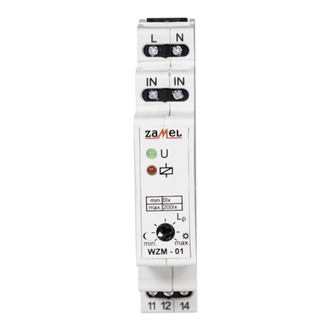
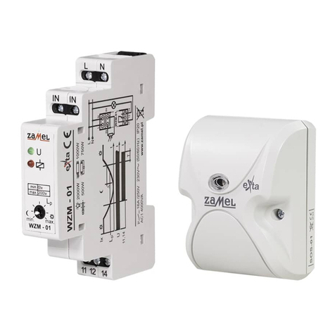
TWILIGHT SWITCH WZM-01 INSTRUCTION MANUAL
APPEARANCE
ver. 0.4.1 _ 2006.06.27_14:00
FEATURES
TECHNICAL PARAMETERS
DESCRIPTION
WZM - 01
Input (supply) terminals: L, N
Input rated voltage: 230 V~
Input voltage tolerance: from -15 to +10 %
Nominal frequency: 50 / 60 Hz
Rated power consumption: 24 mA
Input rated indicator: LED green
Lighting sensor terminals: IN, IN
Sensor cable maximum length: 50 m (MTY 2x 0,5 mm2)
Time adjustment range: from 0 to 200 lx (rotational potentiometer)
Relay indicator: LED red
Output relay parameters: 1NO/NC - 16 A / 250 V AC1 4000 VA
Number of terminal clamps: 7
Section of connecting cables: from 0,2 to 2,50 mm2
Ambient temperature range: from -20 to +45 oC
Operating position: any
Mounting: TH35 rail (EN 60715)
Protection degree: IP20 (EN 60529)
Protective class: II
Overvoltage category: II
Pollution degree: 2
Rated impulse withstand voltage: 1 kV (EN 61000-4-5)
Dimensions (height / width / depth): monomodular (17,5 mm) 90x17,5x66 mm
Weight: 75 g
Reference standards: EN 60669-1, EN 60669-2-1
EN 61000-4-2,3,4,5,6,11
ی Itallowstoswitchonorswitchofflighting
devices according to the preset ambient
light level,
ی inputratedindicator,
ی relayindicator,
ی adjustmentoftheswitchonthreshold,
ی widesettingscopeoftheswitchonthres-
hold (from 0 to 200 lx),
ی thesystemrequiresexternallightsensor,
ی system requires outer light intensity
sensor (e.g. SOH-01, SOH-03, SOH-05),
ی resistanttomomentarychangesoflumi-
nousuxdensity,
ی hysteresisoftheswitch-overthreshold,
ی relay output – one change-over contact
max 16 A capacity.
The twilight switch WZM-01 is used
to control lighting devices and other energy
receiversdependingonluminousuxdens-
ity. The system switches on the lighting at
dusk and switches off at dawn. The swit-
ching on threshold can be adjusted by the
user. The system is resistant to momentary
changes of luminous ux density and the
same guarantees its reliability. External
luminous ux density sensor SOH with a
cable of 50 m maximum length enables the
sensor to be put in a suitable place.
Zakład Mechaniki i Elektroniki
ZAMEL sp.j.
J.W.Dzida,K.Łodzińska
ul. Zielona 27, 43-200 Pszczyna, Poland
Tel. +48 (32) 210 46 65, Fax +48 (32) 210 80 04
www.zamel.pl, e-mail: [email protected]
The device is designed
for one-phase installation
and must be installed in
accordance with standar-
ds valid in a particular co-
untry. The device should
be connected according
to the details included in this operating ma-
nual. Installation, connection and control
should be carried out by a qualied elec-
trician staff, who act in accordance with the
service manual and the device functions.
Disassembling of the device is equal with
a loss of guarantee and can cause electric
shock. Before installation make sure the
connection cables are not under voltage.
The cruciform head screwdriver 3,5 mm
should be used to instal the device. Im-
proper transport, storage, and use of the
deviceinuenceitswrongfunctioning.Itis
not advisable to instal the device in the fol-
lowing cases: if any device part is missing
or the device is damaged or deformed. In
case of improper functioning of the device
contact the producer.
CAUTION
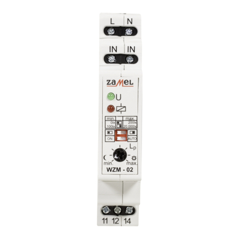
Input rated indicator
Input (supply) terminals (L) Input (supply) terminals (N)
Switchingonthresholdadjustment
Relay indicator
Output (load) relay terminals
(11, 12, 14)
Light sensor input
terminals (IN, IN)
ver. 0.4.1 _ 2006.06.27_14:00
MOUNTING, FUNCTIONING CONNECTING
1. Disconnect the power supply from the
mains by the phase fuse, the circuit-bre-
aker or the switch-disconnector that are
joined to the proper circuit,
2. Check if there is no voltage on connec-
tion cables by means of a special mea-
sure equipment,
3. Install WZM-01 device in the switchboard
on TH-35 DIN rail,
4. Connect the cables with the terminals
according to installing diagram,
5. Switch on the power supply from the
mains,
6. Adjust the demanded switch on time by
means of a potentiometer.
The system works properly after switching
on the power supply from the mains. Turning the
potentiometer in the direction of „ ” causes the
lighting device to switch on at lower lighting level, in
the direction of „
☼
” causes the device to switch on
at higher lighting level. In case the inner sensor’s
luminousuxdensityfallsbelowthepresetthres-
hold the system switches on the output relay and
its lighting devices. The relay is switched on until
theluminousuxdensityisoverthepresetthres-
hold. Using the luminous ux density hysteresis
(delta) and relay switching off time delay (T) makes
the system resistant to momentary and accidental
sensor lighting. While mounting the twilight switch
pay attention the switched on lighting does not
disturb the functioning of the external light sensor.
EXAMPLE OF INSTALLATION
DIMENSIONS
PRODUCT FAMILY
GUARANTEE CARD
There is 24 months guarantee on the product
Salesman stamp and signature, date of sale
1. ZAMEL provides a two-year warranty for its products.
2. The ZAMEL warranty does not cover:
a) mechanical defects resulting from transport, loading / unloading or other circumstances,
b) defects resulting from incorrect installation or operation of ZAMEL products,
c) defects resulting from any changes made by CUSTOMERS or third parties, to products sold or equipment necessary
for the correct operation of products sold,
d) defects resulting from force majeure or other aleatory events for which ZAMEL is not liable.
3. All complaints in relation to the warranty must be provided by the CUSTOMER in writing to the retailer after discovering
a defect.
4. ZAMEL will review complaints in accordance with existing regulations.
5. The way a complaint is settled, e.g. replacement of the product, repair or refund, is left to the discretion of ZAMEL.
Luminous
uxdensity 200 lx 35 lx 20 lx 2 lx
Position of
potentiometer 0 lx 200 lx
☼
0 lx 200 lx
☼
0 lx 200 lx
☼
0 lx 200 lx
☼
The twilight switch WZM-01 belongs to the
twilight switches WZx family.
TIME COURSE
t
☼☼
t
∆
11,14
U
lx
T
t
Lp
∆≈5 ÷ 60 lx
T≈30 s
RELAY CAPACITY
INNER DIAGRAM
LIGHT SENSOR FAMILY
Sensor: Lenght:
SOH - 01 1 m
SOH - 03 3 m
SOH - 05 5 m
Typical application:
The twilight switch operates the light control functions (e.g. garden lighting). The
light sensor should be installed in a place which is not directly illuminated by lights
that are operated by this twilight switch.
LIGHT
SENSOR
LIGHT
SENSOR

Other Zamel Switch manuals

Zamel exta WZM-01 Series User manual

Zamel

Zamel exta WZM-01 Series User manual

Zamel Ledix WDN-03 User manual

Zamel

Zamel Ledix WDN-03 User manual

Zamel RWS-311D/Z User manual

Zamel

Zamel RWS-311D/Z User manual

Zamel stiro RWS-211D/N User manual

Zamel

Zamel stiro RWS-211D/N User manual

Zamel RWS-311D User manual

Zamel

Zamel RWS-311D User manual

Zamel exta APM-10 User manual

Zamel

Zamel exta APM-10 User manual

Zamel RWS-311D/Z User manual

Zamel

Zamel RWS-311D/Z User manual

Zamel Ledix WDN-01 User manual

Zamel

Zamel Ledix WDN-01 User manual

Zamel TWILIGHT SWITCH WZM-02 User manual

Zamel

Zamel TWILIGHT SWITCH WZM-02 User manual

Zamel GRM-10 User manual

Zamel

Zamel GRM-10 User manual

Zamel EXTA APM-20 User manual

Zamel

Zamel EXTA APM-20 User manual

Zamel GRG-01 User manual

Zamel

Zamel GRG-01 User manual

Zamel GRL-01 User manual

Zamel

Zamel GRL-01 User manual

Zamel YNSTA PDJ-213 User manual

Zamel

Zamel YNSTA PDJ-213 User manual

Zamel WZM-01/SOS User manual

Zamel

Zamel WZM-01/SOS User manual

Zamel Ynsta PDJ-213P User manual

Zamel

Zamel Ynsta PDJ-213P User manual

Zamel exta WZH-01 User manual

Zamel

Zamel exta WZH-01 User manual

Zamel EXTA WZM-02 User manual

Zamel

Zamel EXTA WZM-02 User manual

Zamel stiro RWS-211J/N User manual

Zamel

Zamel stiro RWS-211J/N User manual

Popular Switch manuals by other brands

CAMBRIONIX TS3-C10 user manual

CAMBRIONIX

CAMBRIONIX TS3-C10 user manual

PA FL3 manual

PA

PA FL3 manual

LevelOne GEP-2651 user manual

LevelOne

LevelOne GEP-2651 user manual

Robertshaw 5318B instruction manual

Robertshaw

Robertshaw 5318B instruction manual

LEGRAND Niloe LE-764500 user manual

LEGRAND

LEGRAND Niloe LE-764500 user manual

Surecom EP-816X user guide

Surecom

Surecom EP-816X user guide

Rockwell Automation Allen-Bradley Lifeline 4 Application Technique

Rockwell Automation

Rockwell Automation Allen-Bradley Lifeline 4 Application Technique

GarrettCom Magnum CSG14 Installation and user guide

GarrettCom

GarrettCom Magnum CSG14 Installation and user guide

edisio EFPW-W2 manual

edisio

edisio EFPW-W2 manual

Eaton Cutler-Hammer CHGENLC100ATS1SE O & M Manual

Eaton

Eaton Cutler-Hammer CHGENLC100ATS1SE O & M Manual

Guntermann & Drunck DL-MUX2-MC2 Installation and operating guide

Guntermann & Drunck

Guntermann & Drunck DL-MUX2-MC2 Installation and operating guide

HP 6125XLG Command reference

HP

HP 6125XLG Command reference

NETGEAR GSM712 installation guide

NETGEAR

NETGEAR GSM712 installation guide

D-Link DAS-3324 quick start guide

D-Link

D-Link DAS-3324 quick start guide

LevelOne GTL-2691 installation guide

LevelOne

LevelOne GTL-2691 installation guide

Borri STS 16A user manual

Borri

Borri STS 16A user manual

Pickering 40-184A user manual

Pickering

Pickering 40-184A user manual

CAMDEN CM-9800 installation instructions

CAMDEN

CAMDEN CM-9800 installation instructions

manuals.online logo
manuals.online logoBrands
  • About & Mission
  • Contact us
  • Privacy Policy
  • Terms and Conditions

Copyright 2025 Manuals.Online. All Rights Reserved.