zipldr_setup&operations
www.OmniTurn.com support@OmniTurn.com (541) 332-7004 (541)-332-1018 fax
Fast... Precise... Affordable...
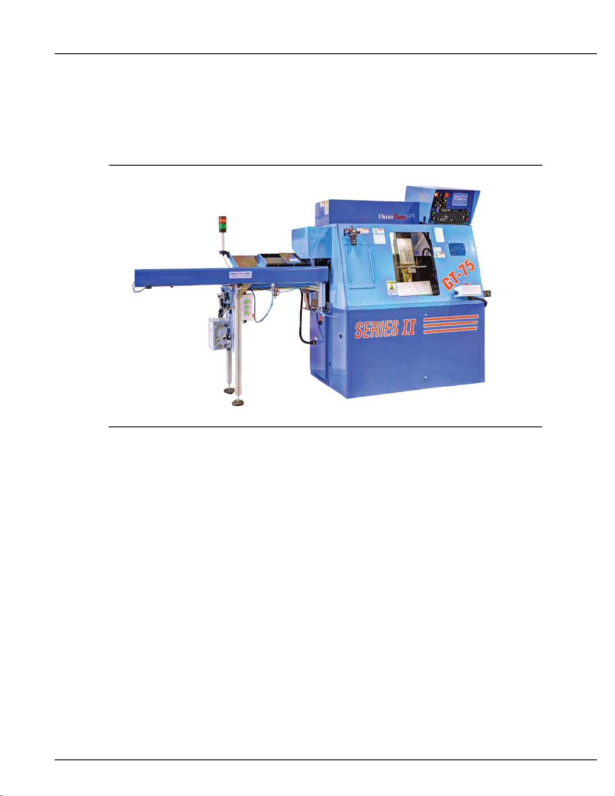
Zip Loader Setup & Operations
OmniTurn
Page 2 of 44
Table of Contents
Section 1: Component Descriptions
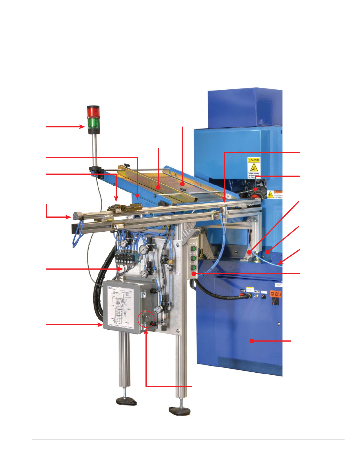
Zip Loader w/Hopper: Major Components. . . . . . . . . . 3
Component Parts, Overview . . . . . . . . . . . . . . . . . . . . 4
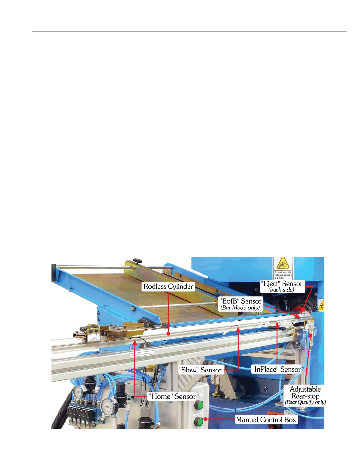
Component Parts, Sensors . . . . . . . . . . . . . . . . . . . . . 5
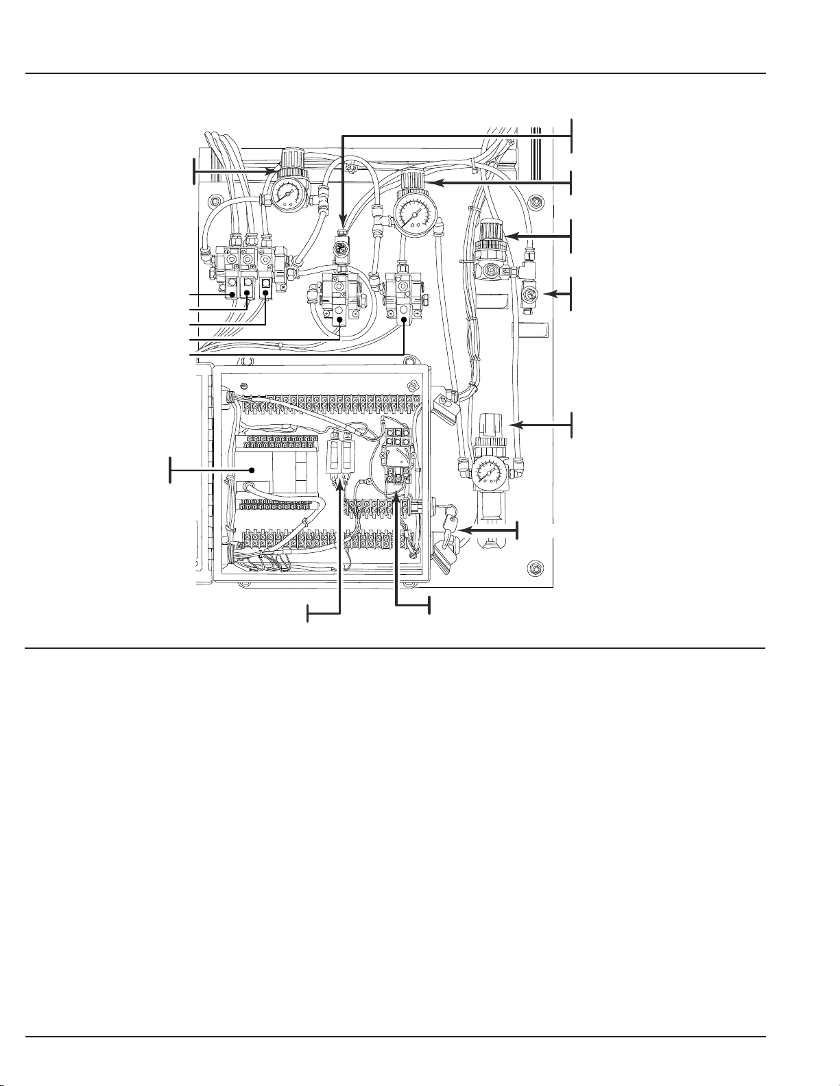
Component Parts, Air Panel . . . . . . . . . . . . . . . . . . . . 6
About Pressure & Speed. . . . . . . . . . . . . . . . . . . . . . . 6
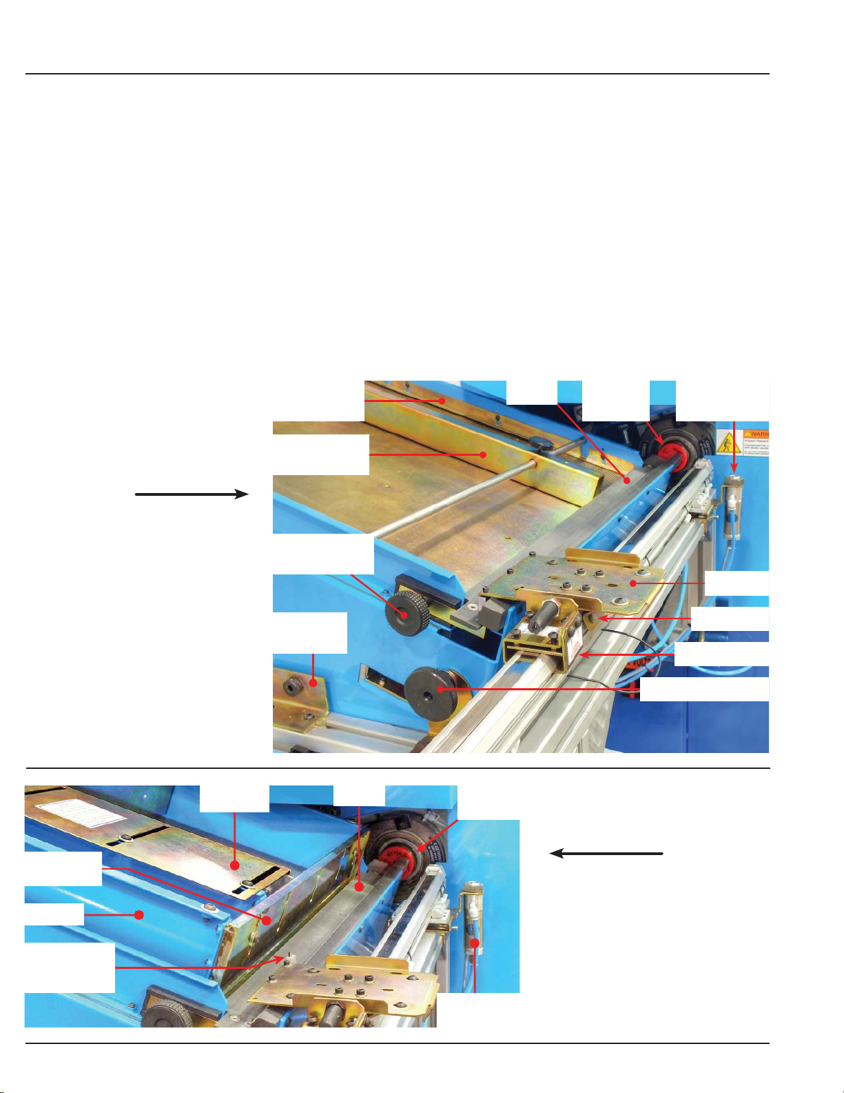
Component Parts, Tray-guide Shoulders . . . . . . . . . . 7
Component Parts, Knife-down Jack-screws . . . . . . . . 7
Component Parts, Manual Control Box. . . . . . . . . . . . 7
Component Parts, Tray Pivot. . . . . . . . . . . . . . . . . . . . 8
Component Parts, Micrometer Adjustment . . . . . . . . . 8
Component Parts, Vee & Pushrod. . . . . . . . . . . . . . . . 9
Component Parts, Optional Hopper . . . . . . . . . . . . . . 9
Pusher and Push-rods. . . . . . . . . . . . . . . . . . . . . . . . . 10
Push-rods for small diameter parts . . . . . . . . . . . . . . . 10
Vee & 1/8” pushrod adjustment. . . . . . . . . . . . . . . . . . 11
1/8” Push-rod and Pushrod Adapter . . . . . . . . . . . . . . 11
Section 2: Setup and Alignment
Loader Setup and Alignment, Mechanical. . . . . . . . . . 12
Loader Setup and Alignment, Electrical. . . . . . . . . . . . 13
Loader Setup and Alignment, Air. . . . . . . . . . . . . . . . . 14
System Test, Manual. . . . . . . . . . . . . . . . . . . . . . . . . . 14
Loader Alignment and Changing Diameters . . . . . . . . 15
Aligning the Shuttle Plate Assembly . . . . . . . . . . . . . . 16
Aligning the loader for Small Diameter Parts. . . . . . . . 17
Section 3: Hopper
Hopper Operational Description . . . . . . . . . . . . . . . . . 18
Adjusting the Hopper. . . . . . . . . . . . . . . . . . . . . . . . . . 18
Hopper Adjustments, 1/8” and 1/16” in Knife. . . . . . . . 19
Section 4: Operation
Using the Loader. . . . . . . . . . . . . . . . . . . . . . . . . . . . . 20
All Modes. . . . . . . . . . . . . . . . . . . . . . . . . . . . . . . . . . . 21
Bar Mode (M50). . . . . . . . . . . . . . . . . . . . . . . . . . . . . . 22
Part Mode (M51) . . . . . . . . . . . . . . . . . . . . . . . . . . . . . 25
Stop Mode (M52). . . . . . . . . . . . . . . . . . . . . . . . . . . . . 30
2Part Mode (M53) . . . . . . . . . . . . . . . . . . . . . . . . . . . . 33
PLC Faults. . . . . . . . . . . . . . . . . . . . . . . . . . . . . . . . . . 34
M-Functions. . . . . . . . . . . . . . . . . . . . . . . . . . . . . . . . . 35
M97 - Jump to Sub-routine, Conditional . . . . . . . . . . . 36
Lubrication. . . . . . . . . . . . . . . . . . . . . . . . . . . . . . . . . . 36
Air Panel Parts List . . . . . . . . . . . . . . . . . . . . . . . . . . . 37
Shuttle Components Parts List . . . . . . . . . . . . . . . . . . 38
Section 5: Technical Documents . . . . . . . . . . . . . . . 39
Index . . . . . . . . . . . . . . . . . . . . . . . . . . . . . . . . . . . . . . 44