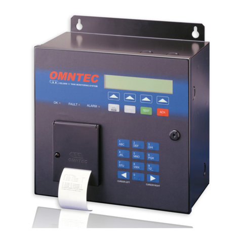
Omntec OEL8000II User manual

OMNTE
C
®Mfg., Inc.
1993 Pond Rd., Ronkonkoma, NY 11779 Tank Gauging • Liquid Level and Leak Detection Systems • Relays
OEL8000II
Installation Manual
Version 5.33E August 2006
OMNTEC
FAULT ALARMOK
1
ABC 2
DEF 3
GHI
4
JKL 5
MNO 6
PQR
7
STU 8
V
WX 9
Y
Z
_
0
- .
,
CURSOR RIGHT
CURSOR LEFT
PRINT
TEST ACK
MENU
DEL
OEL800OII TANK MONITORING SYSTEM
Don’t VOID Your Warranty!
Warranty will be void if OMNTEC®
EC-2 (Belden#8761) cable is not used
with MTG-series probe.
To initiate the warranty the warranty
card provided with this manual must be
completed and returned.
MTG PROBES MUST USE
BELDEN#8761 OR
OMNTEC® EC-2 CABLE.
LEAK SENSORS CAN
USE EQUIVELANT TO
OMNTEC® EC-4 OR
BELDEN#9940.


OEL8000II
Installation Manual
iii
PROPRIETARY INFORMATION NOTICE
This document contains information and material developed by OMNTEC®Mfg., Inc.
All rights are reserved.
No part of this document may be reproduced, transmitted, processed or recorded by any
means or form, electronic, mechanical, photographic or otherwise, without the express
written consent of OMNTEC®Mfg., Inc.
Printed in the United States of America
© Copyright 2007 OMNTEC®Mfg., Inc.


OEL8000II
Installation Manual
v
NOTICE
Use of unauthorized parts in the OEL8000II system or modification to any parts of the
system will nullify U.L. listing and our warranty. OMNTEC®Mfg., Inc. will not be
responsible for any liability claims arising from the performance of modified units.
If you have any questions, please contact OMNTEC®Mfg., Inc. at (631) 981-2001.


OEL8000II
Installation Manual
vii
OMNTEC LIMITED WARRANTY
The seller, OMNTEC Mfg., Inc. warrants to buyer that product is free of defects when
properly installed and maintained by user. Warranty period is one year from date of
installation or 15 months from date of shipment from factory, whichever occurs first. The
seller’s sole obligation is to repair or replace parts found to be defective upon evaluation
by OMNTEC. Parts can be returned for evaluation by requesting an RMA (Return
Material Authorization) from OMNTEC. The liability of the seller shall not exceed the
price paid for components found to be defective. The above warranty is exclusive of all
other warranties whether implied or expressed. Seller assumes no obligation for special
or indirect damages incurred by user.
OMNTEC warranty for custom probes, custom controllers, add ons, spare or replacement
parts is for 90 days from date of shipment. All items must be properly installed for
warranty to be valid. Any items found to have factory defects after evaluation by
OMNTEC through return material authorization process, will be repaired or replaced.
The liability of seller shall not exceed price paid for item found to be defective by factory
evaluation. The above warranty is exclusive of all other warranties whether implied or
expressed. OMNTEC assumes no responsibility or obligation for special or indirect
damages incurred by user.


OEL8000II
Installation Manual
ix
Table of Contents
READ THIS FIRST!..........................................................................................................XIII
SECTION 1 OVERVIEW............................................................................................ 1-1
1.1 SYSTEM DESCRIPTION ............................................................................................... 1-1
1.2 SAFETY...................................................................................................................... 1-1
1.3 UNPACKING,INSPECTION AND DAMAGE CLAIMS...................................................... 1-2
1.4 RETURNS ................................................................................................................... 1-3
1.5 ELECTRICAL WIRING................................................................................................. 1-3
1.5.1 Wires and Cables.............................................................................................. 1-3
1.5.2 Conduits ........................................................................................................... 1-4
SECTION 2 EQUIPMENT.......................................................................................... 2-1
2.1 CONTROLLER............................................................................................................. 2-1
2.1.1 Preparation ...................................................................................................... 2-1
2.1.2 BX-Series Sensor Worksheet ............................................................................ 2-2
2.1.3 Tank Tilt ........................................................................................................... 2-2
2.2 CONTROLLER INSTALLATION .................................................................................... 2-3
2.2.1 Mounting the Controller................................................................................... 2-4
2.2.2 Wiring and Controller Knockout Designations................................................ 2-4
2.2.3 Junction Boxes.................................................................................................. 2-5
2.2.4 EYS Seal Off Fitting ......................................................................................... 2-5
2.2.5 AC Power Line ................................................................................................. 2-6
2.2.6 Telephone Connections at the Controller......................................................... 2-6
2.2.7 AC Power Connections at the Controller......................................................... 2-6
2.2.8 Main Panel and Sub-Panel Grounding ............................................................ 2-7
2.3 MAGNETOSTRICTIVE (MTG) PROBE.......................................................................... 2-7
2.3.1 MTG Probe Length........................................................................................... 2-8
2.3.2 Riser Pipe for MTG Probe ............................................................................... 2-8
2.3.2.1 Riser Pipe Minimum Length Requirements............................................................2-9
2.3.2.2 Riser Pipe Maximum Length Requirements...........................................................2-9
2.3.3 MTG Probe Installation ................................................................................. 2-10
2.3.4 MTG Probe Field Wiring ............................................................................... 2-10
2.3.4.1 Probe Cable ..........................................................................................................2-11
2.3.4.2 MTG Probe Connections at the Controller ...........................................................2-11
2.4 SENSORS.................................................................................................................. 2-12
2.4.1 Sensor Cable................................................................................................... 2-13
2.4.2 BX-PDWF Sensor........................................................................................... 2-13
2.4.2.1 Riser Pipe for BX-PDWF.....................................................................................2-14
2.4.2.2 BX-PDWF Installation .........................................................................................2-15
2.4.3 BX-PDWS....................................................................................................... 2-16
2.4.3.1 Riser Pipe for BX-PDWS.....................................................................................2-16
2.4.3.2 BX-PDWS Installation .........................................................................................2-17
2.4.4 BX-PDS .......................................................................................................... 2-17
2.4.5 BX-L12, BX-L20, BX-LV Series...................................................................... 2-19
2.4.5.1 Riser Pipe for BX-L12, BX-L20, BX-LV Series..................................................2-19
2.4.5.2 BX-L12, BX-L20, BX-LV Installation.................................................................2-19
2.4.6 BX-LM* Series ............................................................................................... 2-20
2.4.6.1 Riser Pipe for BX-LM* Series..............................................................................2-20
2.4.6.2 BX-LM* Installation ............................................................................................2-20
2.4.7 BX-RES........................................................................................................... 2-21
2.4.7.1 Riser Pipe for BX-RES.........................................................................................2-22

Table of Contents
x OMNTEC®Mfg., Inc.
2.4.7.2 BX-RES Installation.............................................................................................2-22
2.4.8 BX-LS ............................................................................................................. 2-23
2.4.9 BX-LSR........................................................................................................... 2-24
2.4.10 BX-LWF.......................................................................................................... 2-24
2.4.10.1 Riser Pipe for BX-LWF........................................................................................2-24
2.4.10.2 BX-LWF Installation............................................................................................2-25
2.4.11 BX-TC............................................................................................................. 2-25
2.4.12 BX-VS............................................................................................................. 2-27
2.4.13 FIELD WIRING.............................................................................................. 2-27
2.5 ANNUNCIATORS (RAS SERIES) ............................................................................... 2-28
2.5.1 Mounting the Annunciator.............................................................................. 2-29
2.5.2 Wiring for Annunciators................................................................................. 2-29
2.5.3 Wiring Configuration for Annunciators ......................................................... 2-30
2.5.4 Annunciator Connections at the Controller ................................................... 2-31
2.6 INTERFACE BOARDS (IB-SERIES) ............................................................................ 2-32
2.7 REMOTE COMMUNICATIONS.................................................................................... 2-33
SECTION 3 APPLYING POWER.............................................................................. 3-1
3.1 PREPARATIONS.......................................................................................................... 3-1
3.2 CHECKLIST ................................................................................................................ 3-1
3.3 SYSTEM START-UP CHECKLIST.................................................................................. 3-2
3.4 CONNECTING POWER................................................................................................. 3-3
SECTION 4 PROGRAMMING .................................................................................. 4-1
4.1 PREPARATION............................................................................................................ 4-1
4.2 PROCEDURE............................................................................................................... 4-2
4.2.1 LCD Display..................................................................................................... 4-2
4.2.2 Tactile Keypad.................................................................................................. 4-2
4.2.3 Printer .............................................................................................................. 4-3
4.3 PROGRAMMING PROCEDURES.................................................................................... 4-3
4.3.1 Entering the SETUP Mode............................................................................... 4-5
4.3.2 Entering the Security Code............................................................................... 4-5
4.3.3 Location Data................................................................................................... 4-8
4.3.3.1 Site Name ...............................................................................................................4-8
4.3.3.2 New Security Code.................................................................................................4-9
4.3.3.3. Preprogrammed Data..............................................................................................4-9
4.3.3.4 Site Address Line 1...............................................................................................4-10
4.3.3.5 Site Address Line 2...............................................................................................4-10
4.3.3.6 Site City................................................................................................................4-10
4.3.3.7 Site State...............................................................................................................4-11
4.3.3.8 Site Zip Code........................................................................................................4-11
4.3.3.9 Site Phone Number...............................................................................................4-11
4.3.3.10 Site Manager’s Name ...........................................................................................4-12
4.3.3.11 Site Identification Number....................................................................................4-12
4.3.3.12 Site Print Header...................................................................................................4-12
4.3.3.13 CITLD Enable Code.............................................................................................4-13
4.3.3.14 Ullage Percentage.................................................................................................4-13
4.3.4 Tank Data....................................................................................................... 4-14
4.3.4.1a Copying Tank Data...............................................................................................4-14
4.3.4.1b Tank Identification................................................................................................4-16
4.3.4.2 Level Probe – Enable/Disable...............................................................................4-16
4.3.4.3 Product Type.........................................................................................................4-17
4.3.4.4 Coefficient of Thermal Expansion........................................................................4-17
4.3.4.5 Tank Tilt...............................................................................................................4-18
4.3.4.6 Product Height......................................................................................................4-18
4.3.4.7 Water Height.........................................................................................................4-19
4.3.4.8 Thermistor Type...................................................................................................4-20
4.3.4.9 Probe Wire Speed.................................................................................................4-20
4.3.4.10 High Water Alarm Point.......................................................................................4-21

OEL8000II
Installation Manual
xi
4.3.4.11 Low/Low Product Alarm Point.............................................................................4-21
4.3.4.12 Delivery Needed Alarm Point...............................................................................4-22
4.3.4.13 Low Product Point................................................................................................4-22
4.3.4.14 High Product Point ...............................................................................................4-22
4.3.4.15 High Product Warning Point.................................................................................4-23
4.3.4.16 Overfill Product Alarm Point................................................................................4-23
4.3.4.17 High/High Product Alarm Point ...........................................................................4-23
4.3.4.18 Tank Diameter......................................................................................................4-23
4.3.4.19 Probe Length.........................................................................................................4-24
4.3.4.20 Tank Capacity.......................................................................................................4-24
4.3.4.21 Volume Offset ......................................................................................................4-24
4.3.4.22 Automated VLD (Volume Leak Detection Test)..................................................4-25
4.3.4.23 Sudden Loss Limit................................................................................................4-27
4.3.4.24 Table Size.............................................................................................................4-27
4.3.5 Sensor Data.................................................................................................... 4-28
4.3.5.1 Config (Sensor) Submenu.....................................................................................4-30
4.3.5.1.1 Sensor Labeling............................................................................................4-31
4.3.5.1.2 Other Label...................................................................................................4-34
4.3.5.1.3 Editing Sensor Labels...................................................................................4-35
4.3.5.1.4 Temperature Sensor Programming...............................................................4-37
4.3.5.1.5 Vapor Sensor Programming .........................................................................4-38
4.3.5.2 Test/Del (Sensor) Submenu..................................................................................4-41
4.3.5.2.1 Testing and Deleting Sensors........................................................................4-41
4.3.5.2.2 Setting Sensor Priority..................................................................................4-43
4.3.6 Clearing Logs (Alarm, Drop, CITLD, and VLD) ........................................... 4-45
4.3.7 Shift Data........................................................................................................ 4-46
4.3.8 Remote Data................................................................................................... 4-48
4.3.8.1 Site Alarm Acknowledge Time ............................................................................4-49
4.3.8.2 Remote Horn Timeout..........................................................................................4-49
4.3.8.3 Remote Horn Time Enable/Disable......................................................................4-50
4.3.9 Comm ............................................................................................................. 4-51
4.3.9.1 Serial.....................................................................................................................4-51
4.3.9.1.1 COM1 ...........................................................................................................4-52
4.3.9.1.2 COM2 ...........................................................................................................4-53
4.3.9.1.3 COM3 ...........................................................................................................4-56
4.3.9.2 Modem..................................................................................................................4-57
4.3.9.2.1 Autofax and Datamodem...............................................................................4-58
4.3.9.2.2 Ip Modem......................................................................................................4-60
4.3.9.3 RS485...................................................................................................................4-60
4.3.10 Int Brd ............................................................................................................ 4-61
4.3.10.1 Programming the IB-RB2 Relay Board................................................................4-62
4.3.10.1.1 Tank Activation.............................................................................................4-64
4.3.10.1.2 Sensor Activation (non-product distinguishing)............................................4-65
4.3.10.1.3 Sensor Activation (product distinguishing)...................................................4-65
4.3.10.1.4 Temperature (BX-TC) Sensor Activation......................................................4-66
4.3.10.2 Programming the IB-C420 Board.........................................................................4-67
4.3.10.3 Programming the IB-12V Low Voltage Board.....................................................4-68
4.3.10.4 Programming the IB-NET Board..........................................................................4-68
4.3.11 Report............................................................................................................. 4-68
4.3.12 Units............................................................................................................... 4-69
4.3.13 Language........................................................................................................ 4-70
SECTION 5 PROCEDURES ....................................................................................... 5-1
5.1 LOOPBACK TEST........................................................................................................ 5-1
5.2 SETTING PRODUCT AND WATER HEIGHT (CALIBRATION) ......................................... 5-1
5.3 ON DEMAND VLD TESTING ...................................................................................... 5-1
5.4 REMOTE TESTING OF RAS ANNUNCIATOR ................................................................ 5-1
5.5 REPLACING CONTROLLER BATTERIES....................................................................... 5-1
5.6 TROUBLESHOOTING SENSORS.................................................................................... 5-2
5.6.1 Condition #1..................................................................................................... 5-2

Table of Contents
xii OMNTEC®Mfg., Inc.
5.6.2 Condition #2..................................................................................................... 5-2
5.7 TROUBLESHOOTING PROBE GUIDE............................................................................ 5-3
5.7.1 Condition #1 – Status: High Water .................................................................. 5-3
5.7.2 Condition #2 – Status: Timeout Error on all Probes........................................ 5-4
5.7.3 Condition #3 – Status: Timeout Error on one Probe........................................ 5-4
5.7.4 Condition #4 – Status: Incorrect Product Level............................................... 5-5
5.8 PROGRAMMING CLD................................................................................................. 5-8
APPENDIX A PROBES.................................................................................................. A-1
APPENDIX B SENSORS.................................................................................................B-1
APPENDIX C CONNECTOR SEALING KITS........................................................... C-1
APPENDIX D OEL8000II CONTROLLER................................................................. D-1
APPENDIX E REMOTE ANNUNCIATOR..................................................................E-1
APPENDIX F INTERFACE BOARDS..........................................................................F-1
APPENDIX G MODEM................................................................................................... 5-1

OEL8000II
Installation Manual
xiii
Read This First!
The OEL8000II has been designed using intrinsically safe principals and is
Underwriters Laboratories (U.L.) listed, CUL listed, and CE listed for petroleum
storage tanks. It is approved for Class I, Groups C and D or Class I, Zone 0, Group
IIB Hazardous locations when connected in accordance with control drawing number
CDOEL8000II.
All work must be performed only by authorized personnel who are qualified
using intrinsically safe design principles (NEC procedures) and are thoroughly
familiar with the OEL8000II Installation Manual. At a minimum, it is the
installer’s responsibility to be familiar with and to comply with intrinsic design
principles as defined in the National Electrical Code. It is also the installer’s
responsibility to be familiar with and to comply with applicable local codes.
Improper wiring or installation can compromise the intrinsically safe design of
the system and create an electric shock or explosion hazard. YOU CAN CAUSE
DEATH OR SERIOUS PERSONAL INJURY TO YOURSELF AND OTHERS
AND EXTENSIVE PROPERTY DAMAGE.
Observe the following rules. Failure to do so will create an electric shock or
explosion hazard that can result in death, personal injury, or property damage.
1. Do not permit unauthorized personnel to install or service the equipment.
2. Power to the controller must be removed before installing or servicing the
equipment.
WARNING
WARNING


OEL8000II
Installation Manual
xv
IMPORTANT SENSOR INFORMATION
***
ONLY INSTALL BX-SERIES SENSORS
WITH THE OEL8000II
***
Please verify sensors have been installed according to the
worksheet provided before calling technical support.


OEL8000II
Installation Manual
xvii
Don’t VOID Your Warranty!
Warranty will be void if OMNTEC EC-2 (Belden #8761)
cable is not used with MTG-series probes.
READ ME!
Earth Ground Warning
The earth ground terminal must be connected to maintain
intrinsic safety as well as UL and NEC.
Use Proper Knockouts
If preformed knockouts are not used, warranty will be void.
Please verify sensors have been installed according
to the worksheet provided before calling technical
support.
READ ME!


OEL8000II
Installation Manual
1-1
Section 1 Overview
1.1 System Description
The OMNTEC OEL8000II is a comprehensive tank gauging and leak detection
system designed to bring tank owners into compliance with EPA regulations. It
provides real time simultaneous monitoring of up to eight tanks, identifying water
and product levels as well as leaks in single or double-wall steel and fiberglass tank
systems. Up to forty-four Bright Eye series leak and level detection sensors can be
added for monitoring interstitial spaces, piping sumps, double wall piping, dispenser
pans, dikes, and observation wells. Alarm conditions are identified by the controller
and optional low voltage remote high level annunciators. An additional option
features independently programmable relays that can be used for automatically
shutting down pumps and/or dispensers upon detection of a leak, low product level,
or high product level. The OEL8000II also provides a user friendly inventory
management system for identifying usage and alerting the customer to low inventory.
The system consists of a controller that is wall mounted in a non-hazardous location
and a combination of probes and sensors for monitoring water and product levels,
temperatures, and leaks. System programming and status reporting are achieved via
the controller. Remote communication capability can be provided by an internal
14,400 baud fax / modem, RS232, RS485, 4-20 mA card, IB-NET card (internet) or
relay outputs. Easy to read status and inventory data is provided on the controller’s
LCD display while a hard copy can be obtained from the 36 character thermal printer.
Reporting is programmable or available on demand.
The OMNTEC OEL8000II is an intrinsically safe system and is Underwriters
Laboratories listed for petroleum storage tanks. Refer to third party certifications for
performance specifications.
1.2 Safety
To install or service any component of the OEL8000II system the individual must be
qualified using intrinsically safe design principles (NEC practices) and must be
familiar with the specifications and procedures described within this manual. It is the
responsibility of the installer and operator to be familiar with and to comply with all
codes and regulations. Before you begin, read Section 3 – Applying Power. When
you have finished, return to the beginning, and read the entire manual. The following
are some safety tips to be used during installation and servicing:

Overview
1-2 OMNTEC®Mfg., Inc.
♦Do not perform any installation or service procedures if you are not qualified to
work with intrinsically-safe systems.
♦Do not perform any installation or service procedures if you are not familiar with
the National Electrical Code and all other federal, state, and local codes and
regulations pertaining to this installation.
♦Do not perform any installation or service procedures until you have read through
and understand this entire manual.
♦Do not install the controller in a hazardous location.
♦Do not drill through enclosure
♦Do not mount outdoors without ENC-4X weather proof enclosure
♦Do not install RAS series remote Annunciators in hazardous locations.
♦Only sensors and probes are to be installed within hazardous locations.
♦Do not substitute components. The intrinsic safety design can become
compromised creating an explosion hazard. It will also void the warranty.
♦Do not apply power to the controller until all of the other installations and wiring
have been completed and inspected. Read Section 3 – Applying Power. Applying
power to the controller and programming the controller are the final steps in the
installation process.
♦Always remove power to the controller before servicing.
♦Take all safety precautions to avoid accidents.
♦Keep work area clean.
♦Block off work area when working on tanks and hazardous locations to prevent
vehicles and pedestrians from entering the area.
♦Use proper fire prevention measures to keep all sparks, flames, and other ignition
devices away from the hazardous area.
1.3 Unpacking, Inspection and Damage Claims
Unpack and thoroughly inspect all equipment before accepting receipt from carrier. If
you detect or suspect any damage or loss, do the following:
♦Write a detailed description of the damage or loss on the front of the bill of lading
and sign it.
♦Have the carrier’s agent sign the bill of lading.
♦Immediately notify the carrier by phone and follow up in writing within 48 hours.
The buyer assumes all risk for damage or loss of merchandise incurred during
shipping and is responsible for filing and settling any claims. If you report your loss
to OMNTEC®Mfg., Inc. however, we will attempt to assist you with your claim.
Other manuals for OEL8000II
1
Table of contents
Other Omntec Measuring Instrument manuals