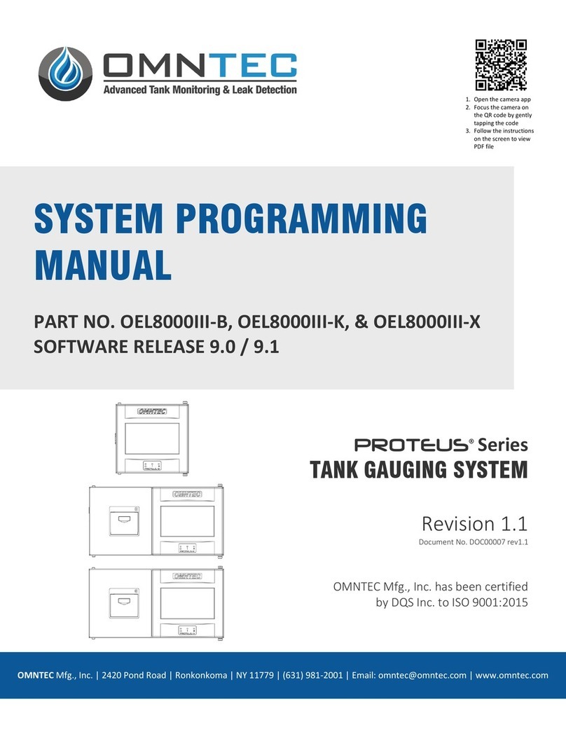
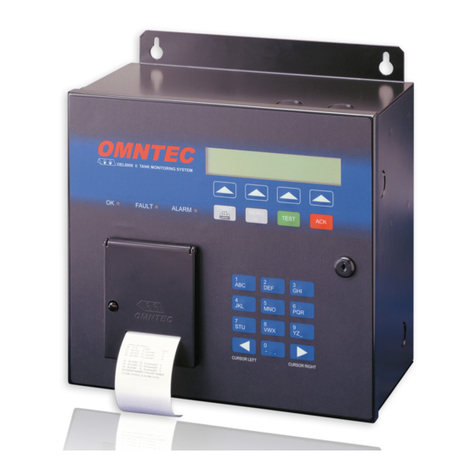
Omntec PROTEUS OEL8000III Series User manual

PROTEUS
OMNTEC Mfg., Inc., 2420 Pond Road, Ronkonkoma, NY 11779
Phone (631) 981-2001 Fax (631) 981-2007 www.OMNTEC.com
File Name: DE00014 DE00015 DE00020-10 rev2045.docx Page 1 of 71 Rev Date: 10-15-2021
Serial Interface Manual
OEL8000III Series Models K/X
OEL8000III-K/X
SERIAL INTERFACE MANUAL
OMNTEC Mfg., Inc. has been certified by DQS Inc. to ISO 9001:2015

PROTEUS
OMNTEC Mfg., Inc., 2420 Pond Road, Ronkonkoma, NY 11779
Phone (631) 981-2001 Fax (631) 981-2007 www.OMNTEC.com
File Name: DE00014 DE00015 DE00020-10 rev2045.docx Page 2 of 71 Rev Date: 10-15-2021
Serial Interface Manual
OEL8000III Series Models K/X
Table of Contents
1.0 INTRODUCTION ........................................................................................................................................................................ 4
2.0 HARDWARE CONNECTIONS...................................................................................................................................................... 4
2.1 RS-232 ...................................................................................................................................................................................... 4
2.2 EXTERNAL MODEM .................................................................................................................................................................. 4
3.0 CHARACTER FORMAT ............................................................................................................................................................... 5
3.1 COMMAND MESSAGE FORMAT ............................................................................................................................................... 5
4.0 RESPONSE MESSAGE FORMAT ................................................................................................................................................. 5
4.1 COMPUTER FORMAT................................................................................................................................................................ 6
4.2 DISPLAY FORMAT ..................................................................................................................................................................... 6
5.0 OEL8000III-K/X COMM Ports.................................................................................................................................................... 7
6.0 OEL8000III-K/X SERIAL COMMUNICATIONS SETUP.................................................................................................................. 8
7.0 FUNCTION CODES AND RESPONSE MESSAGES ........................................................................................................................ 9
8.0 REMOTE TROUBLESHOOTING TECHNIQUES .......................................................................................................................... 10
8.2 LOOP BACK TEST 1.................................................................................................................................................................. 10
9.0 ASCII HEX FLOATING POINT FORMAT..................................................................................................................................... 11
VISUAL BASIC CHECKSUM PROGRAMMING EXAMPLE................................................................................................................. 14
THREE CHARACTER COMMANDS ......................................................................................................................................... 15
Command: 10T Inventory Report................................................................................................................................................. 16
Command: 15T Delivery Report ................................................................................................................................................... 17
Command: 160 Clear Delivery Reports ........................................................................................................................................ 18
Command: 1AT Probe Alarm Status Report................................................................................................................................. 19
Command: 500 Set Calendar Clock .............................................................................................................................................. 20
Command: 599 Set Calendar Clock with seconds ........................................................................................................................ 21
Command: A80 ID Revision Level Request................................................................................................................................... 22
FIVE CHARACTER COMMANDS............................................................................................................................................. 23
Command: 003 Remote Alarm Reset........................................................................................................................................... 24
Command: 051 Clear In-Tank Delivery Reports ........................................................................................................................... 25
Command: 101 System Status Report.......................................................................................................................................... 26
Command: 102 System Configuration Report ............................................................................................................................. 28
Command: 111 Alarm History Report .......................................................................................................................................... 29
Command: 112 Non-Priority Alarm History Report ..................................................................................................................... 31
Command: 201 In-Tank Inventory Report.................................................................................................................................... 32
Command: 202 In-Tank Delivery Report ...................................................................................................................................... 33
Command: 203 In-Tank Leak Detect Report ................................................................................................................................ 35
Command: 205 In-Tank Status Report ......................................................................................................................................... 36
Command: 206 In-Tank Alarm History Report ............................................................................................................................. 37
Command: 207 In-Tank Leak Test History Report........................................................................................................................ 38
Command: 208 In-Tank Leak Test Results Report........................................................................................................................ 40
Command: 251 (VLD) Test Report................................................................................................................................................ 41
Command: 301 Liquid Sensor Status Report................................................................................................................................ 42
Command: 302 Sensor Alarm History Report .............................................................................................................................. 44
Command: 501 Set Time and Date .............................................................................................................................................. 46
Command: 505 / 517 Inquire system units & language............................................................................................................... 47
Command: OMNTEC 517 Inquire Individual System Units .......................................................................................................... 48
Command: 601 Inquire Tank Enable ............................................................................................................................................ 49
Command: 602 Set Tank Product Label ....................................................................................................................................... 50

PROTEUS
OMNTEC Mfg., Inc., 2420 Pond Road, Ronkonkoma, NY 11779
Phone (631) 981-2001 Fax (631) 981-2007 www.OMNTEC.com
File Name: DE00014 DE00015 DE00020-10 rev2045.docx Page 3 of 71 Rev Date: 10-15-2021
Serial Interface Manual
OEL8000III Series Models K/X
Command: 603 Set Product Code ................................................................................................................................................ 51
Command: 604 Tank Full Height Volume..................................................................................................................................... 52
Command: 607 Tank Diameter .................................................................................................................................................... 53
Command: 621 Tank Low Level Limit........................................................................................................................................... 54
Command: 622 Tank High Level Limit .......................................................................................................................................... 55
Command: 624 Tank High Water Level Limit ............................................................................................................................... 56
Command: 701 Inquire Sensor Configuration.............................................................................................................................. 57
Command: 702 Set Liquid Sensor Location Label ........................................................................................................................ 58
Command: 902 Inquire System Version....................................................................................................................................... 59
OEL8000III-X DIAGNOSTIC COMMANDS ............................................................................................................................... 60
Command: TEST 1 (Inventory Readings) ...................................................................................................................................... 61
Command: TEST 2 (Probe Communications) ............................................................................................................................... 62
Command: TEST 3 (Average Temp and Five Thermistors) ........................................................................................................... 63
OEL8000III-X VIEW LOG DATA COMMANDS ......................................................................................................................... 64
Command: PSL (Print Shift Log).................................................................................................................................................... 65
Command: PDL (Print Delivery Log ) ............................................................................................................................................ 66
Command: PVLD (Print VLD Log).................................................................................................................................................. 67
Command: PVL (Print VLD Log) – Table Format ........................................................................................................................... 68
Command: PAL (Print Alarm Log)................................................................................................................................................. 69
Command: PCL (Print CITLD Log) ................................................................................................................................................. 70
Command: PCC (Print Current CITLD Log).................................................................................................................................... 71

PROTEUS
OMNTEC Mfg., Inc., 2420 Pond Road, Ronkonkoma, NY 11779
Phone (631) 981-2001 Fax (631) 981-2007 www.OMNTEC.com
File Name: DE00014 DE00015 DE00020-10 rev2045.docx Page 4 of 71 Rev Date: 10-15-2021
Serial Interface Manual
OEL8000III Series Models K/X
1.0 INTRODUCTION
The OEL8000III-K/X Tank Monitoring System has two modes for remote communication, used to connect the
system to a controlling computer.
1. Serial RS-232 interface.
3. Ethernet interface.
2.0 HARDWARE CONNECTIONS
The RS-232 interface is accessed via a 9-pin D-connector located on the left (K) or bottom-left (X) of the console.
2.1 RS-232
The RS-232 D-connector is a panel mount, 9-pin female type, wired in a Data Terminal Equipment (DTE)
configuration.
RS-232 signals are wired to the female D-connector as follows:
Communications rate is selectable:
Baud: 1200, 2400, 4800, 9600, 38400, or 57600 baud.
Data Bits: 7, or 8data bits.
Parity: Odd, Even, or None parity.
Stop bits: 1, or 2.
*Note: Defaults italicized and bolded.
The RS-232 specification is designed for operation up to 75 feet. Direct connect cables greater than 50 feet are not
warranted for proper operation.
2.2 EXTERNAL MODEM
The optional external modem operates at up to 9600 Baud. The modem module plugs into the RS232 port.
Pin #
Function
Pin 2
Transmit Data
Pin 3
Receive Data
Pin 5
Signal Ground

PROTEUS
OMNTEC Mfg., Inc., 2420 Pond Road, Ronkonkoma, NY 11779
Phone (631) 981-2001 Fax (631) 981-2007 www.OMNTEC.com
File Name: DE00014 DE00015 DE00020-10 rev2045.docx Page 5 of 71 Rev Date: 10-15-2021
Serial Interface Manual
OEL8000III Series Models K/X
2.3 ETHERNET INTERFACE
The Ethernet interface is located on the left (K) or bottom-left (X) of the controller beside the RS-232 port.
3.0 CHARACTER FORMAT
The system receives and sends characters via all interfaces in an ASCII format. Characters are not echoed when
received, and transmitted characters must not be echoed back to the system.
3.1 COMMAND MESSAGE FORMAT
All command and response messages are configured in a format which includes a control character(s), a function
code and a data field. The control characters are described in this section while the function codes and data field
messages are described in subsequent sections.
The system responds to a command message that has the following configuration:
SOH | Format Char | Command Code | Data Field
SOH is a control-A character (ASCII 01). Start of string.
The Format Character (I, i, S, s) determines the type of command and response. A upper-case format character
will return a response in display format. A lower-case format character will return a response in computer format.
“I, i” = information response. “S, s” = set command.
The Command Code is a three or six character command code which the system interprets to determine the type of
action to take. System command codes and response messages are defined in subsequent sections.
The Data Field contains information necessary to perform the selected function (such as tank number and setup
information).
4.0 RESPONSE MESSAGE FORMAT
There are two types of response message formats: computer (or compressed data format) and display format. Each
format uses a different format character.
If the system receives a command message string containing a function code that it does not recognize, it will
respond with a <SOH>9999FF1B<ETX>. The "9999" indicates that the system has not understood the command,
while the "FF1B" is the appropriate checksum for the preceding <SOH>9999 string.

PROTEUS
OMNTEC Mfg., Inc., 2420 Pond Road, Ronkonkoma, NY 11779
Phone (631) 981-2001 Fax (631) 981-2007 www.OMNTEC.com
File Name: DE00014 DE00015 DE00020-10 rev2045.docx Page 6 of 71 Rev Date: 10-15-2021
Serial Interface Manual
OEL8000III Series Models K/X
4.1 COMPUTER FORMAT
The computer format is a stream of numbers without any formatting characters; i.e., carriage return, line feed,
spaces, labels, etc. The message format is as follows:
SOH | Format Char | Command Code | Data Field | 9 | Checksum | ETX (TLS-250 compatible)
SOH | Format Char | Command Code | Data Field | && | Checksum | ETX (TLS-350 compatible)
The SOH is a Control-A character (ASCII 01). Start of string.
The Format Character (I, i, S, s, t) determines the type of command and response. A upper-case format character
will return a response in display format. A lower-case format character will return a response in computer format.
“I, i, t” = information response. “S, s” = set command.
The Command Code is identical to the received command message function code.
The Data Field contains the response message which is described in subsequent sections.
The "&&" or “9” is a fixed tag character which indicates that the checksum immediately follows.
The Checksum is a series of four ASCII-hexadecimal characters which provide a check on the integrity of all the
characters preceding it, including the control characters. The four characters represent a 16-bit binary count which
is the 2's complemented sum of the 8-bit binary representation of the message characters after the parity bit (if
enabled) has been cleared.
The data integrity check can be done by converting the four checksum characters to the 16-bit binary number and
adding the 8-bit binary representation of the message characters to it. The binary result should be zero. (see section
9.0)
The ETX end of string character is programmable. The default ETX character is a Control-C character (ASCII 03).
Caution should be taken before changing the ETX character, because it affects the transmitted messages on ALL
communications ports of the system, and additional host devices may be connected to other ports which expect the
ETX to be a Control-C.
4.2 DISPLAY FORMAT
The display format is intended for display on a CRT. It includes all the necessary formatting characters such as
carriage returns, line feeds, nulls, spaces, labels, etc. to view the data

PROTEUS
OMNTEC Mfg., Inc., 2420 Pond Road, Ronkonkoma, NY 11779
Phone (631) 981-2001 Fax (631) 981-2007 www.OMNTEC.com
File Name: DE00014 DE00015 DE00020-10 rev2045.docx Page 7 of 71 Rev Date: 10-15-2021
Serial Interface Manual
OEL8000III Series Models K/X
5.0 OEL8000III-K/X COMM Ports
Ethernet
The Ethernet port is used as a remote control port, to retrieve
tank / sensor data or to change the settings in the OEL8000III-K/X. The Ethernet port is also
used for the embedded web server, and e-mail functionality.
Micro USB
The micro USB is reserved for future use.
RS-232
The RS-232 port is used as the main remote control port, to retrieve
tank / sensor data or to change the settings in the OEL8000III-KX.
CABLING for RS-232:
Wiring - Pins 2 to 2, 3 to 3, and 5 to 5
Any standard RS232 cable will work. Do not use a null modem cable.
MICRO USB
RJ45, Ethernet
DB9, Female
RS232 Comm Port

PROTEUS
OMNTEC Mfg., Inc., 2420 Pond Road, Ronkonkoma, NY 11779
Phone (631) 981-2001 Fax (631) 981-2007 www.OMNTEC.com
File Name: DE00014 DE00015 DE00020-10 rev2045.docx Page 8 of 71 Rev Date: 10-15-2021
Serial Interface Manual
OEL8000III Series Models K/X
6.0 OEL8000III-K/X SERIAL COMMUNICATIONS SETUP
To Navigate to SETUP Press UTILITIES
Utilities Screen: To Enter Setup Press
SETUP MENU
Enter Password: You will be prompted for
a password to enter setup, the default is 000000
Setup Menu (Page 1): Press COMM PORTS
Comm Port Settings: Used to program
settings of on-board RS-232 port
Data Bits: Selections available are 8, or 7.
Parity: Selections available are None, Odd, or Even.
Stop Bits: Selections available 1, or 2.
Comm Type: Selections available Remote, or Modbus.
SETUP MODBUS button will navigate to Modbus
Settings Page

PROTEUS
OMNTEC Mfg., Inc., 2420 Pond Road, Ronkonkoma, NY 11779
Phone (631) 981-2001 Fax (631) 981-2007 www.OMNTEC.com
File Name: DE00014 DE00015 DE00020-10 rev2045.docx Page 9 of 71 Rev Date: 10-15-2021
Serial Interface Manual
OEL8000III Series Models K/X
7.0 FUNCTION CODES AND RESPONSE MESSAGES
The remote commands fall into the following major groupings:
Five Character Commands
Function Codes Response Types
003 to 051 ........................................................Control Functions
101 to 111 .............................................. Operational Reports (System)
201 to 208 .............................................. Operational Reports (In-tank)
301 to 302 ...............................................Operational Reports (Sensor)
501 ....................................................Setup Functions & Reports (System)
601 to 624 .........................................Setup Functions & Reports (In-tank)
701 to 702 .........................................Setup Functions & Reports (Sensor)
902 ....................................................Setup Functions & Reports (System Diagnostics)
Three Character Commands
Function Codes Response Types
100 to 160 .............................................. Operational Reports (In-tank)
500 to 599 .........................................Setup Functions & Reports (In-tank)

PROTEUS
OMNTEC Mfg., Inc., 2420 Pond Road, Ronkonkoma, NY 11779
Phone (631) 981-2001 Fax (631) 981-2007 www.OMNTEC.com
File Name: DE00014 DE00015 DE00020-10 rev2045.docx Page 10 of 71 Rev Date: 10-15-2021
Serial Interface Manual
OEL8000III Series Models K/X
8.0 REMOTE TROUBLESHOOTING TECHNIQUES
8.1 SERIAL SETUP
a) Make sure that a one to one serial cable (pins 2,3 and 5 used) is used from the computer to the OEL8000III-K/X.
Make sure that the RS232 connector is firmly connected into RS-232 port on the bottom-left of the controller.
b) Check the OEL8000III-K/X’s setup menu for the proper serial protocol. See section 6 for details.
8.2 LOOP BACK TEST 1 – Test cabling from computer to OEL8000III-K/Xfor continuity and
functionality.
Connect a serial cable from a computer to a loop-back connector or jumper pins 2 and 3 on the serial cable.
From a terminal program on your computer (most computers have Hyper-terminal installed) select the proper baud
rate settings and select connect.
Next, type in any character from the keyboard. The character typed should appear on the computers screen (two
times if echo is enabled in the terminal programs setup).
If the character appears correctly on the screen that means that the communication is reaching the OEL8000III-K/X
properly.
What is happening is that the command is being sent through the serial port from Hyper-terminal, through the cable
and jumper (in the OEL8000III-K/X), then back to computer’s serial port and into hyper-terminal. This procedure
will test the continuity of the wiring and computers serial port’s functionality.
If the above test does not work, use a continuity checker and check the connections from the computer to the three
pin connector in the OEL8000III-K/X.

PROTEUS
OMNTEC Mfg., Inc., 2420 Pond Road, Ronkonkoma, NY 11779
Phone (631) 981-2001 Fax (631) 981-2007 www.OMNTEC.com
File Name: DE00014 DE00015 DE00020-10 rev2045.docx Page 11 of 71 Rev Date: 10-15-2021
Serial Interface Manual
OEL8000III Series Models K/X
9.0 ASCII HEX FLOATING POINT FORMAT
Some remote commands use an ASCII Hex format when transmitting or receiving numbers. This procedure will
explain how to convert a number from decimal to ASCII Hex and from ASCII Hex to decimal.
Floating Point Numbers
There are two problems with integers; they cannot express fractions, and the range of the number is limited to the
number of bits used. An efficient way of storing fractions is called the floating point method, which involves
splitting the fraction into two parts, an exponent and a mantissa.
The exponent represents a value raised to the power of 2.
The mantissa represents a fractional value between 0 and 1.
Consider the number
12.50
The number is first converted into the format
2n * 0.xxxxxx
where n represents the exponent and 0.xxxxx is the mantissa.
The computer industry agreed upon a standard for the storage of floating point numbers. It is called the IEEE 754
standard, and uses 32 bits of memory (for single precision), or 64 bits (for double precision accuracy). The single
precision format looks like,
Bits
31 30 29 28 27 26 25 24 23 22 21 20 19 18 17 16 15 14 13 12 11 10 9 8 7 6 5 4 3 2 1 0
+---+-----------------------+---------------------------------------------------------------------+
| S | Exponent value | Mantissa value |
+---+-----------------------+---------------------------------------------------------------------+
S = Sign Bit
The sign bit is 1 for a negative mantissa, and 0 for a positive mantissa.
The exponent uses a bias of 127.
The mantissa is stored as a binary value using an encoding technique.
Working out the FP bit patterns
The number we have is
12.5
which expressed as fraction to the power of 2 is,
12.5 / 2 = 6.25
6.25 / 2 = 3.125
3.125 / 2 = 1.5625
1.5625 / 2 = 0.78125
NOTE: Keep dividing by 2 till a fraction between 0 and 1 results. The fraction is the mantissa value, the number of

PROTEUS
OMNTEC Mfg., Inc., 2420 Pond Road, Ronkonkoma, NY 11779
Phone (631) 981-2001 Fax (631) 981-2007 www.OMNTEC.com
File Name: DE00014 DE00015 DE00020-10 rev2045.docx Page 12 of 71 Rev Date: 10-15-2021
Serial Interface Manual
OEL8000III Series Models K/X
divisions is the exponent value.
thus our values now are,
0.78125 * (2*2*2*2) (comment: this is 2 to the power of 4) = 12.5
The exponent bit pattern is stored using an excess of 127. This means that this value is added to the exponent when
storing (and subtracted when removing).
The exponent bit pattern to store is,
4 + 127 = 131 decimal = '10000011 Hex'
As the mantissa is a positive value, the sign bit is 0.
The mantissa is a little more complicated to work out. Each bit represents 2 to the power of a negative number. It
looks like,
1st bit of mantissa = 0.5
2nd = 0.25
3rd = 0.125
4th = 0.0625
5th = 0.03125
etc
The mantissa number value we have is 0.78125, which in binary is
11001000000000000000000 (0.5 + 0.25 + 0.03125) = 0.78125
However, to make matters even more complicated, the mantissa is normalized, by moving the bit patterns to the left
(each shift subtracts one from the exponent value) till the first 1 drops off.
The resulting pattern is then stored.
The mantissa now becomes
10010000000000000000000
and the exponent is adjusted to become
131 - 1 = 130 = '10000010'
The final assembled format is,
Bits
31 30 29 28 27 26 25 24 23 22 21 20 19 18 17 16 15 14 13 12 11 10 9 8 7 6 5 4 3 2 1 0
+--+-----------------------+---------------------------------------------------------------------+
| 0| 1 0 0 0 0 0 1 0| 1 0 0 1 0 0 0 0 0 0 0 0 0 0 0 0 0 0 0 0 0 0 0 |
+--+-----------------------+---------------------------------------------------------------------+
S Exponent Mantissa
which equals = 0100 0001 0100 1000 0000 0000 0000 0000 Hex = 41480000 Hexadecimal ( = FFFFFFFF used in
command)

PROTEUS
OMNTEC Mfg., Inc., 2420 Pond Road, Ronkonkoma, NY 11779
Phone (631) 981-2001 Fax (631) 981-2007 www.OMNTEC.com
File Name: DE00014 DE00015 DE00020-10 rev2045.docx Page 13 of 71 Rev Date: 10-15-2021
Serial Interface Manual
OEL8000III Series Models K/X
Now lets convert the following ASCII Hex format back into a decimal number.
Bits
31 30 29 28 27 26 25 24 23 22 21 20 19 18 17 16 15 14 13 12 11 10 9 8 7 6 5 4 3 2 1 0
+--+-----------------------+---------------------------------------------------------------------+
| 0| 1 0 0 0 0 0 1 0| 1 0 0 1 0 0 0 0 0 0 0 0 0 0 0 0 0 0 0 0 0 0 0 |
+--+-----------------------+---------------------------------------------------------------------+
S Exponent Mantissa
Sign bit is 0 = positive number.
The exponent value of, 10000010 Hex = 2^1 + 2^7 = 130 decimal
130 - 127 = 3
And a mantissa value of, 10010000000000000000000 Hex = 2^22 + 2^19 = 4718592 decimal
bit 22 = 0.5, bit 21 = 0.25, etc
1 + (4718592 / 8388608) = 1.5625 OR 1 + ( 0.5 + 0.0625 ) = 1.5625
thus the number is,
1.5625 * 2^3 = 12.5

PROTEUS
OMNTEC Mfg., Inc., 2420 Pond Road, Ronkonkoma, NY 11779
Phone (631) 981-2001 Fax (631) 981-2007 www.OMNTEC.com
File Name: DE00014 DE00015 DE00020-10 rev2045.docx Page 14 of 71 Rev Date: 10-15-2021
Serial Interface Manual
OEL8000III Series Models K/X
VISUAL BASIC CHECKSUM PROGRAMMING EXAMPLE
Check the checksum on OMNTEC Five Charactor/TLS350 protocol
'”Instring” contains current response string.
'The addition of all of the characters(except checksum) converted back to
'a four character hex string should equal the checksum string.
Private Sub check_checksum()
'Read four characters after the ‘&&’ termination.
stpt = (InStr(1, InString, "&&")) 'Find the ‘&&’ termination characters.
If (Len(InString) < stpt + 4) Then Exit Sub 'Are CHECKSUM characters in the response.
chsum = Mid(InString, stpt + 2, 4) 'Store the four checksum characters.
i = 1
'Add the all characters in the string together except the four checksum characters.
Do While (i < stpt + 2)
chk_sum = chk_sum + Asc(Mid(InString, i, 1))
i = i + 1
Loop
chk_sum = chk_sum Mod 65536 'AND with 0xFFFF (round off).
chk_sum = Hex(&H10000 - chk_sum) 'Perform 2’s complement(Invert plus one), save as
'a hex string.
'Put zero's to format string to 4 places if needed.
If Len(chk_sum) < 4 Then cksm_lgh = 4 - Len(chk_sum)
For X = 1 To cksm_lgh
chk_sum = "0" & chk_sum
Next X
End If
'Compare strings, checksum with calculated value.
If (chsum = chk_sum) Then
checksum_0k = 1 'If checksum is OK.
Else
checksum_0k = 0 'Else checksum is bad.
End If
End Sub
Check the checksum on OMNTEC three Charactor/TLS250 protocol
The three character command checksum is calculated the same as in the above example accept that the termination
character(s) ‘&&’ is a ‘9’ before the checksum characters. Check that the fifth character from the end of the string
is a ‘9’ then store the last four characters as the checksum.

PROTEUS
OMNTEC Mfg., Inc., 2420 Pond Road, Ronkonkoma, NY 11779
Phone (631) 981-2001 Fax (631) 981-2007 www.OMNTEC.com
File Name: DE00014 DE00015 DE00020-10 rev2045.docx Page 15 of 71 Rev Date: 10-15-2021
Serial Interface Manual
OEL8000III Series Models K/X
Three Character Commands

PROTEUS
OMNTEC Mfg., Inc., 2420 Pond Road, Ronkonkoma, NY 11779
Phone (631) 981-2001 Fax (631) 981-2007 www.OMNTEC.com
File Name: DE00014 DE00015 DE00020-10 rev2045.docx Page 16 of 71 Rev Date: 10-15-2021
Serial Interface Manual
OEL8000III Series Models K/X
Command: 10T Inventory Report
Command Format: <S0H>10T
Typical Response Message:
<S0H>100MMDDHHmmsssTPssssIIIhhGGGGGGSFFFtGGGGGGWW(W)t.... (W) – see Note 10
TPssssIIIhhGGGGGGSFFFtGGGGGGWW(W)t9CCCC<ETX>
Notes:
1. MMDDHHmm - Current Date and Time(month, day, hours, minutes)
2. sss - Three system status characters:
a. The first "s" is always ‘0’
b. The second "s" is always ‘0’
c. The third "s" is always ‘0’
3. T - Tank Number (Decimal, 0 = all)
4. P - Product code character (set by function 55T)
5. ssss -Four tank status characters:
a. The first "s" is "1" if the tank is "enabled"
b. The second "s" is "1" if the tank is "enabled"
c. The third "s" is unused (always 0)
d. The fourth "s" is "1" if there is a delivery-in-progress
6. IIIhh - Fuel level in inches and hundredths
7. GGGGGG - Fuel volume in gallons
8. SFFFt - Fuel temperature in degrees Fahrenheit and tenths with a preceding sign
character (0 or -)
9. GGGGGG - Tank ullage in gallons
10. WWt - Water level in inches and tenths (Inches)
10. WWWt - Water level in inches and tenths (Millimeters)
11. 9 - Data Termination Flag
12. CCCC - Message Checksum

PROTEUS
OMNTEC Mfg., Inc., 2420 Pond Road, Ronkonkoma, NY 11779
Phone (631) 981-2001 Fax (631) 981-2007 www.OMNTEC.com
File Name: DE00014 DE00015 DE00020-10 rev2045.docx Page 17 of 71 Rev Date: 10-15-2021
Serial Interface Manual
OEL8000III Series Models K/X
Command: 15T Delivery Report
Command Format: <S0H>15T
Typical Response Message:
<S0H>150TPrrMMDDHHmmGGGGGGSFFFtMMDDHHmmGGGGGGSFFFt....
TPrrMMDDHHmmGGGGGGSFFFtMMDDHHmmGGGGGGSFFFt....9CCCC<ETX>
Notes:
1. T - Tank Number (Decimal, 0 = all)
2. P - Product code character (set by function 55T)
3. rr - Number of delivery reports to follow for the tank. If it is 00, no
reports are included in the response for this tank
1. MMDDHHmm – Starting Current Date and Time(month, day, hours, minutes).
2. GGGGGG – Starting Fuel volume in gallons
3. SFFFt – Starting Fuel temperature in degrees Fahrenheit and tenths with a
preceding sign character (0 or -)
7. MMDDHHmm – Ending Current Date and Time(month, day, hours, minutes).
8. GGGGGG – Ending Fuel volume in gallons
9. SFFFt – Ending Fuel temperature in degrees Fahrenheit and tenths
with a preceding sign character (0 or -)
10. 9 - Data Termination Flag
11. CCCC - Message Checksum

PROTEUS
OMNTEC Mfg., Inc., 2420 Pond Road, Ronkonkoma, NY 11779
Phone (631) 981-2001 Fax (631) 981-2007 www.OMNTEC.com
File Name: DE00014 DE00015 DE00020-10 rev2045.docx Page 18 of 71 Rev Date: 10-15-2021
Serial Interface Manual
OEL8000III Series Models K/X
Command: 160 Clear Delivery Reports
Command Format: <S0H>160
Typical Response Message: <S0H>1609FF2F<ETX>
Notes:
1. The latest Delivery report for each tank is retained

PROTEUS
OMNTEC Mfg., Inc., 2420 Pond Road, Ronkonkoma, NY 11779
Phone (631) 981-2001 Fax (631) 981-2007 www.OMNTEC.com
File Name: DE00014 DE00015 DE00020-10 rev2045.docx Page 19 of 71 Rev Date: 10-15-2021
Serial Interface Manual
OEL8000III Series Models K/X
Command: 1AT Probe Alarm Status Report
Command Format: <S0H>1AT
Typical Response Message:
<S0H>1A0aTPsssss....
TPsssss9CCCC<ETX>
Notes:
1. a - External input status, Always 0
2. T - Tank Number (Decimal, 0 = all)
3. P - Product code character (set by function 55T)
4. sssss – Current alarm status (0=No Alarm, 1=Alarm)
for the following alarm conditions:
1st Leak Alarm
2nd High Water Alarm
3rd High Product Alarm
4th Low Product Alarm
5th Theft Alarm
5. 9 - Data Termination Flag
6. CCCC - Message Checksum

PROTEUS
OMNTEC Mfg., Inc., 2420 Pond Road, Ronkonkoma, NY 11779
Phone (631) 981-2001 Fax (631) 981-2007 www.OMNTEC.com
File Name: DE00014 DE00015 DE00020-10 rev2045.docx Page 20 of 71 Rev Date: 10-15-2021
Serial Interface Manual
OEL8000III Series Models K/X
Command: 500 Set Calendar Clock
Command Format: <S0H>500YYMMDDHHmm
Typical Response Message:
<S0H>500YYMMDDHHmm9CCCC<ETX>
Notes:
1. YYMMDDHHmm - Current Date and Time (year, month, day, hours, minutes)
24-hour time format)
2. 9 - Data Termination Flag
3. CCCC - Message Checksum
Table of contents
Other Omntec Measuring Instrument manuals
Popular Measuring Instrument manuals by other brands

PerfectFlite
PerfectFlite Pnut user manual

Leica Geosystems
Leica Geosystems DISTO S910 quick start

Applent Instruments
Applent Instruments AT381x user guide

Simpson
Simpson Gima instruction manual

Megger
Megger PDS 62-SIN user guide

PCB Piezotronics
PCB Piezotronics 3713B122G/-0002 Installation and operating manual