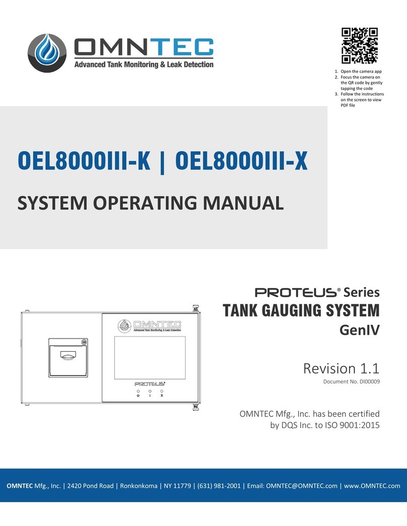
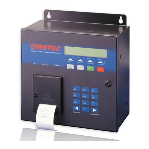
Omntec OEL8000II User manual

OMNTEC®Mfg., Inc.
1993 Pond Rd., Ronkonkoma, NY 11779 Tank Gau
g
in
g
• Li
q
uid Level and Leak Detection S
y
stems •
OEL8000II
Owner’s Manual
Version 5.33E August 2006
OMNTEC
FAULT ALARMOK
1
ABC
2
DEF
3
GHI
4
JKL
5
MNO
6
PQR
7
STU
8
V
WX
9
Y
Z
_
0
- .
,
CURSOR RIGHT
CURSOR LEFT
PRINT
TEST ACK
MENU
DEL
OEL800OII TANK MONITORING SYSTEM


OEL8000II
Owner’s Manual iii
PROPRIETARY INFORMATION NOTICE
This document contains information and material developed by OMNTEC®Mfg., Inc.
All rights are reserved.
No part of this document may be reproduced, transmitted, processed or recorded by any
means or form, electronic, mechanical, photographic or otherwise, without the express
written consent of OMNTEC® Mfg., Inc.
Printed in the United States of America
© Copyright 2007 OMNTEC® Mfg., Inc.


OEL8000II
Owner’s Manual v
NOTICE
Use of unauthorized parts in the OEL8000II system or modification to any parts of the
system will nullify U.L. listing and our warranty. OMNTEC®Mfg., Inc. will not be
responsible for any liability claims arising from the performance of modified units.
If you have any questions, please contact OMNTEC®Mfg., Inc. at (631) 981-2001.


OEL8000II
Owner’s Manual vii
WARRANTY
The seller, OMNTEC Mfg., Inc. warrants to buyer that product is free of defects when
properly installed and maintained by user. Warranty period is one year from date of
installation or 15 months from date of shipment from factory, whichever occurs first. The
seller’s sole obligation is to repair or replace parts found to be defective upon evaluation
by OMNTEC. Parts can be returned for evaluation by requesting an RMA (Return
Material Authorization) from OMNTEC. The liability of the seller shall not exceed the
price paid for components found to be defective. The above warranty is exclusive of all
other warranties whether implied or expressed. Seller assumes no obligation for special
or indirect damages incurred by user.
OMNTEC warranty for custom probes, custom controllers, add ons, spare or replacement
parts is for 90 days from date of shipment. All items must be properly installed for
warranty to be valid. Any items found to have factory defects after evaluation by
OMNTEC through return material authorization process, will be repaired or replaced.
The liability of seller shall not exceed price paid for item found to be defective by factory
evaluation. The above warranty is exclusive of all other warranties whether implied or
expressed. OMNTEC assumes no responsibility or obligation for special or indirect
damages incurred by user.


OEL8000II
Owner’s Manual ix
Table of Contents
READ THIS FIRST!............................................................................................................. XI
SECTION 1 INTRODUCTION................................................................................... 1-1
1.1 THE OEL8000II ........................................................................................................ 1-1
1.2 ABOUT THIS MANUAL ............................................................................................... 1-1
1.3 MANUAL CONVENTIONS............................................................................................ 1-2
SECTION 2 SYSTEM DESCRIPTION...................................................................... 2-1
2.1 MAIN FUNCTIONS...................................................................................................... 2-1
2.2 SYSTEM COMPONENTS .............................................................................................. 2-1
2.2.1 Controller ......................................................................................................... 2-1
2.2.1.1 Controller Front Panel Features.............................................................................. 2-2
2.2.1.2 Self Test.................................................................................................................. 2-2
2.2.1.3 Warnings, Alarms, and Setpoints............................................................................2-3
2.2.1.4 Inventory Management...........................................................................................2-5
2.2.1.5 Volumetric Leak Detection (VLD) .........................................................................2-6
2.2.1.6 System of Measurement..........................................................................................2-6
2.2.1.7 Communications..................................................................................................... 2-7
2.2.2 Probes............................................................................................................... 2-7
2.2.3 Sensors ............................................................................................................. 2-7
2.2.4 Optional Features............................................................................................. 2-7
2.2.4.1 Annunciators (RAS-series Remotes) ......................................................................2-7
2.2.4.2 Interface Boards...................................................................................................... 2-8
2.2.4.3 Remote Communications (OMNTEC-PC interactive software) .............................2-8
2.2.4.4 Additional Options..................................................................................................2-8
SECTION 3 SYSTEM OPERATIONS ....................................................................... 3-1
3.1 CONTROL PANEL ....................................................................................................... 3-1
3.1.1 LCD Display Screen......................................................................................... 3-1
3.1.2 LEDs................................................................................................................. 3-2
3.1.3 Arrow Keys....................................................................................................... 3-2
3.1.4 Function Keys (PRINT, MENU, TEST, and ACK) ........................................... 3-2
3.1.4.1 PRINT Key.............................................................................................................3-3
3.1.4.2 MENU/DELETE Key............................................................................................. 3-3
3.1.4.3 TEST Key...............................................................................................................3-3
3.1.4.4 ACK Key ................................................................................................................ 3-4
3.1.5 Data Keypad..................................................................................................... 3-4
3.1.6 Printer .............................................................................................................. 3-4
3.1.7 Lock and Keys .................................................................................................. 3-5
3.1.8 Horn ................................................................................................................. 3-5
3.2 MENUS,SCREENS,AND PRINTOUTS........................................................................... 3-5
3.2.1 MAIN Menu ...................................................................................................... 3-5
3.2.1.1 Screen #1 (MAIN Menu)........................................................................................3-6
3.2.1.2 Screen #2 (MAIN Menu)........................................................................................3-7
3.2.1.3 Screen #3 (MAIN Menu)........................................................................................3-8
3.2.1.4 Screen #4 (MAIN Menu)........................................................................................3-8
3.2.1.5 Screen #5 (MAIN Menu)........................................................................................3-9
3.2.1.6 Screen #6 (Main Menu) ........................................................................................3-10
3.2.2 Submenus........................................................................................................ 3-10
3.2.2.1 STATUS Submenu ...............................................................................................3-10
3.2.2.2 ALARMS Submenu..............................................................................................3-15

Table of Contents
x OMNTEC®Mfg., Inc.
3.2.2.3 SETUP Submenu..................................................................................................3-17
3.2.2.4 TIME Submenu ....................................................................................................3-17
3.2.2.5 ALRM LOG Submenu .........................................................................................3-18
3.2.2.6 ALRM PRNT Submenu........................................................................................3-19
3.2.2.7 VLD Submenu......................................................................................................3-19
3.2.2.8 DROP E/D Submenu ............................................................................................3-21
3.2.2.9 PRNT DROP Submenu ........................................................................................3-22
3.2.2.10 TMP SNSR Submenu ........................................................................................... 3-23
3.2.2.11 SHIFT LOG Submenu.......................................................................................... 3-24
3.2.2.12 DIAG Submenu ....................................................................................................3-25
3.2.2.13 PRINTER Submenu..............................................................................................3-27
SECTION 4 FUNCTIONS AND PROCEDURES ..................................................... 4-1
4.1 BASIC FUNCTIONS AND PROCEDURES........................................................................ 4-1
4.1.1 Printouts ........................................................................................................... 4-1
4.1.1.1 System Inventory Printout ......................................................................................4-1
4.1.1.2 Inventory Printout for Specific Tank ......................................................................4-1
4.1.1.3 Printout of Alarms and Warnings in Effect.............................................................4-1
4.1.1.4 View/Print Alarm Log ............................................................................................4-2
4.1.1.5 Printout Drop Information ......................................................................................4-2
4.1.1.6 Printout Shift Log Report .......................................................................................4-2
4.1.1.7 Enable/Disable Automatic Printout for Alarm........................................................ 4-2
4.1.1.8 Enable/Disable Automatic Printout upon Drop ......................................................4-3
4.1.2 View Inventory Data......................................................................................... 4-3
4.1.3 View Alarms Currently in Effect....................................................................... 4-3
4.1.4 System Setup ..................................................................................................... 4-3
4.1.5 Changing the Date and Time............................................................................ 4-3
4.1.6 Perform VLD .................................................................................................... 4-4
4.1.7 Enable/Disable Communications ..................................................................... 4-4
4.1.8 Testing Alarms for Product and Water............................................................. 4-4
4.1.9 Data Direction.................................................................................................. 4-4
4.1.10 Remote Testing of RAS Annunciator ................................................................ 4-4
4.2 RESPONDING TO ALARMS .......................................................................................... 4-4
4.3 FAULTS...................................................................................................................... 4-6
4.4 TESTING SYSTEMS ..................................................................................................... 4-6
4.5 LCD FIELDS IN MAIN MENU.................................................................................... 4-6
SECTION 5 FAQ’S FOR OEL8000II ......................................................................... 5-1
FREQUENTLY ASKED QUESTIONS....................................................................................... 5-1
APPENDIX A INSTALLING THERMAL PAPER ..................................................... A-1
A.1 INSTALLING THERMAL PAPER IN THE PRINTER......................................................... A-1
APPENDIX B ELECTRICAL RATINGS .....................................................................B-1
B.1 ELECTRICAL RATINGS FOR THE OEL8000II ..............................................................B-1

OEL8000II
Owner’s Manual xi
Read This First!
The OEL8000II has been designed using intrinsically safe principals and is
Underwriters Laboratories (U.L.) listed, CUL listed, and CE listed for petroleum
storage tanks. It is approved for Class I, Groups C and D or Class I, Zone 0, Group
IIB Hazardous locations when connected in accordance with control drawing number
CDOEL8000II.
Do not attempt to make any other adjustments no matter how simple they may
appear.
All work must be performed only by authorized personnel who are qualified
using intrinsically safe design principles (NEC procedures) and are thoroughly
familiar with the OEL8000II Installation Manual. At a minimum, it is the
installer’s responsibility to be familiar with and to comply with intrinsic design
principles as defined in the National Electrical Code. It is also the installer’s
responsibility to be familiar with and to comply with applicable local codes.
Improper wiring or installation can compromise the intrinsically safe design of
the system and create an electric shock or explosion hazard. YOU CAN CAUSE
DEATH OR SERIOUS PERSONAL INJURY TO YOURSELF AND OTHERS
AND EXTENSIVE PROPERTY DAMAGE.
Observe the following rules. Failure to do so will create an electric shock or
explosion hazard that can result in death, personal injury, or property damage.
1. Do not install or service the equipment yourself.
2. Do not permit unauthorized personnel to install or service the equipment.
WARNING
WARNING

Read This First!
xii OMNTEC®Mfg., Inc.
3. Power to the controller must be removed before installing or servicing the
equipment.
4. The only adjustments that you are allowed to make are:
a. Loading the printer paper.
b. Programming the controller as described in this manual.

OEL8000II
Owner’s Manual 1-1
Section 1 INTRODUCTION
1.1 The OEL8000II
The OMNTEC®Mfg., Inc. OEL8000II is a comprehensive tank gauging and leak
detection system designed to bring tank owners into compliance with EPA
regulations. It provides real time simultaneous monitoring of up to eight tanks,
identifying water and product levels. Up to forty-four additional sensors can be
monitored for detecting discrete liquid levels and leaks. The OEL8000II is also an
effective, user friendly, inventory management system that identifies usage and alerts
the customer to low inventory.
The OEL8000II has been designed to be easy to use, but you can take full advantage
of its capabilities by taking some time to read this manual. If you do nothing else,
make certain that everyone who will have access to the controller reads the previous
section – Read This First!
1.2 About this Manual
This manual is organized into five sections as follows:
Read This First! Users must read and understand this
section thoroughly before reading the
rest of this manual or using the
OEL8000II.
Section 1 Introduction Introduces the OEL8000II system,
discusses safety requirements, and
describes the organization of the
manual.
Section 2 System Description Describes the system features.
Section 3 System Operations Familiarizes the user with the
OEL8000II front panel and describes
the LCD’s menus and submenus.
Section 4 Functions and Procedures Provides instructions for system
functions and procedures.
Section 5 FAQ’s for OEL8000II Provides answers to frequently asked
questions.

Introduction
1-2 OMNTEC®Mfg., Inc.
Appendix A Installing Thermal Paper Provides instructions for replacing the
printer’s paper.
Appendix B Electrical Ratings for the
OEL8000II Contains electrical rating data.
1.3 Manual Conventions
This manual uses the following conventions:
♦Bold indicates emphasis or heading.
♦Note is used to set off important information from the rest of the text.
This manual also uses the following warning and caution formats:
WARNING
The WARNING symbol alerts you to a hazard that
may result death, personal injury, or property
damage.
CAUTION
The CAUTION symbol alerts you that if directions
are not properly followed, the system may not
operate as expected.

OEL8000II
Owners Manual 2-1
Section 2 SYSTEM DESCRIPTION
2.1 Main Functions
The OMNTEC®Mfg., Inc. OEL8000II is an easy to use system that monitors
underground and above ground storage tanks and piping systems. It is used with
single wall and double wall steel or fiberglass tanks. Its two main functions are to
detect leaks and to provide the owner with an efficient inventory monitoring system.
A loud (up to 95 dB) horn and an LED (light emitting diode) on the controller panel
are simultaneously activated to alert the owner when an alarm condition occurs. The
LCD (liquid crystal display) identifies the cause and location of the alarm condition,
and the controller’s optional printer can be used to provide a permanent record of all
data and alarm occurrences.
2.2 System Components
The OEL8000II consists of a controller panel and a combination of probes and
sensors. The probes and sensors are installed in the storage tanks, interstitial spaces,
piping sumps, double wall piping, dispenser pans, dykes, and observation wells for
monitoring the tank contents and detecting leaks. These are connected to the
controller via electrical cables that are run inside conduit. Unlike other types of
electrical installations, special installation and wiring techniques are used by
authorized installers who are qualified using intrinsically safe design principles (NEC
procedures) and are familiar with the OEL8000II Installation Manual.
WARNING
All installations and repairs must be performed by
authorized installers. Do not attempt to perform any
repairs yourself. Failure to comply may create an
electric shock or explosion hazard that can result in
death, personal injury, or property damage.
2.2.1 Controller
The controller is a programmable device that is wall-mounted within a non-hazardous
area where it can be easily seen and heard. It monitors all of the probes and sensors
and alerts the owner when a warning or alarm condition occurs (see Figure 3-1). If
outdoor installation is required, an ENC-4X enclosure, heater, and thermostat are
available. Contact OMNTEC® Mfg. Inc. for assistance.

System Description
2-2 OMNTEC®Mfg., Inc.
2.2.1.1 Controller Front Panel Features
The following features are available or accessible at the Controller’s front panel (see
Figure 3-1).
Note: Some features must be enabled and/or programmed by an authorized installer.
♦LCD
The LCD allows for easy programming of the controller, provides status and
inventory data, and provides immediate identification of warning and alarm
sources.
♦Arrow Keys
The arrow keys are pushbuttons located below the LCD display. To select a field
on the bottom line of the LCD, press the arrow key that points to the field. This
will allow navigation through menus and select functions.
♦Function Keys
Four function keys, located directly below the arrow keys (PRINT, MENU,
TEST, and ACK), allow you to obtain printouts, return to the previous or MAIN
Menu, delete characters on the LCD, initiate system test, and acknowledge
alarms.
♦Data Keypad
The data keypad resembles a telephone keypad containing alpha-numeric
characters and is used for entering data. It also contains CURSOR LEFT and
CURSOR RIGHT keys for positioning the cursor on the LCD.
♦LEDs
Three LEDs are used to indicate system status (OK), detection of a fault condition
(FAULT), and indication of an alarm condition (ALARM).
♦Printer
A 36-character thermal printer can be activated manually or automatically to
provide permanent records.
♦Lock and Keys
The OEL8000II controller has with a lock to prevent internal tampering. The end-
user is provided with two keys. Do not open the controller yourself. Only
authorized and qualified professionals may service or install components in the
OEL8000II system. Contact OMNTEC® Mfg. Inc. for replacement of lost keys.
2.2.1.2 Self Test
When activated by pressing the green TEST key on the controller panel, the self-test
program will test various elements of the system including the RAM, EPROM, LCD,
horn, front panel LED’s, level probes, and the leak sensors. If an optional remote
annunciator is installed, it will also test the annunciator by causing its lights to blink
and horn to sound. The self-test feature includes an automatic printout (see Figure
2-1).

OEL8000II
Owners Manual 2-3
2.2.1.3 Warnings, Alarms, and Setpoints
The OEL8000II controller will respond to certain conditions by initiating an alarm,
warning condition, or a programmed response when the product level rises or drops
to a specific setpoint.
The controller responds to a warning condition by displaying a message on its LCD.
If the system includes a remote annunciator, its LED will flash.
In the event of an alarm, the controller will illuminate its red ALARM LED, activate
its audible alarm, and display a message on its LCD. If the system includes a remote
annunciator, its LED will illuminate and its audible alarm will also be activated.
Pressing the ACK key on the controller’s front panel will silence the horns, but the
LEDs will remain illuminated, and the controller’s LCD will continue to provide
alarm data until the alarm condition has been eliminated.
.
.
.
- - - Testing PROM
Prom Tests OK
- - - Testing RAM PASSED
RAM tests OK
- - -
Testing Level Probes
T# PRODUCT TYPE TEST
T1 DIESEL P
T2 REGULAR P
.
.
.
T8 GAS P
- - -
Testing Leak Sensors
S# P/N LABEL TEST
01 BXLS T 1, Dbl_Wall#: 1 P
(S/N: 000000001)
02 BXLS T 2, Sump#: 1 P
(S/N: 000000002)
03 BXPDS T 3, Dispenser#: 1 P
.
.
.
Figure 2-1: Sample Self-Test Printout

System Description
2-4 OMNTEC®Mfg., Inc.
High/High
Level
Alarm
Overfill
Alarm*
High
Warning
High
Product
Level
Low
Product
Level
Delivery
Needed
Alarm
Low/Low
Level
Alarm
High
Water
Alarm
Sensor
Alarm
Sudden
Loss
Alarm
OEL8000II
Piezo Horn
OEL8000II
Alarm LED
OEL8000II
LCD
Display
X X X
X X X X X
Audible
Alarm
Remote
Annunciator
Flashing
LED
Alarm LED
Remote
Annunciator
Solid LED
Flashing
LED
Remote
Annunciator
Horn
Illuminated
(solid) LED
IB-RB2
Relay
Trigger
Point
X X
X X
X X
X
Other
Response
IB-12V
Trigger
Point
X X
X X
X X
Table 2-1: Controller Alarm and Warning Response
* Factory disabled. End user can enable function and set alarm to trigger at any
level up to 90%.
Following is a description of the system’s warnings, alarms and events. Table 2-1
shows how the system responds to these occurrences.
♦High/High Level Alarm – occurs when the product level in the tank reaches an
emergency height during a fill condition. The factory default value is 90%, but
this can be adjusted up to 95%.
♦Overfill Alarm – similar to High/High Level Alarm. It is factory disabled but can
be enabled by the end user, and the trigger can be set at any level up to 90%.
♦High Warning – occurs when the product level in the tank reaches the
programmed high warning level.
♦High Product Level – occurs when the product in the tank rises to the
programmed high product level. This is a setpoint that can be used to initiate a
programmed response such as triggering a relay. It is not a warning or an alarm.
♦Low Product Level – occurs when the product in the tank drops to the
programmed low product level. This is a setpoint that can be used to initiate a
programmed response such as triggering a relay. It is not a warning or an alarm.
♦Delivery Needed Alarm – occurs when the product level has dropped to a level at
which point a delivery is needed.

OEL8000II
Owners Manual 2-5
♦Low/Low Level Alarm – programmable feature, occurs when the product level in
the tank drops to a critical level.
♦High Water Alarm – programmable feature, it occurs when the water level in the
tank is too high.
♦Sensor Alarm – occurs when a leak has been detected.
♦Sudden Loss Alarm – occurs during VLD testing indicating a large loss that is not
consistent with a leak (e.g., pumping gas while test is in progress).
For all alarms, the LCD and the printer will identify the probe or sensor that initiated
the alarm.
2.2.1.4 Inventory Management
The controller provides product volume data for each tank and maintains logs
showing changes in inventory volume due to deliveries and usage during shifts.
♦Inventory Increase Detection (DROP)
Inventory increase detection determines when a delivery is being made. This
feature is automatically activated when the system detects an increase in volume
that is in excess of a preprogrammed value. Upon activation, the system will wait
for several minutes for the contents to settle and then store the data. The controller
will store data for up to five deliveries per tank and up to forty (40) deliveries for
the entire system. Afterwards, it will delete the oldest data each time a new
delivery is made.
Note: To obtain an automatic printout following a delivery, the DROP mode
must be enabled (see Section 3.2.2.8 – DROP E/D Submenu).
CAUTION
Do not dispense product from tank between delivery
and printout. Failure to comply will yield false data.
♦Shift Function
The Shift function is designed to automatically print tank volume information at
the end of employee shifts. A printout is provided at the end of each employee
shift to reflect that shifts start volume, end volume, and delta volume for each tank
connected to the system. The Shift function can be designed for 1 to 4 different
daily shift times. Below (see Figure 2-2) is an example of the automatic printout
(in this case shift #1 begins at noon and ends at 8:00 PM).
Note: An authorized, qualified installer must program this feature. The installer
should refer to the programming section in the OEL8000II Installation Manual.

System Description
2-6 OMNTEC®Mfg., Inc.
2.2.1.5 Volumetric Leak Detection (VLD)
Using the tank’s magnetostrictive probe, the controller performs a highly accurate
volumetric leak detection test (VLD). The end user has the option of selecting the
0.1 gal/hour or the 0.2 gal/hour EPA standards for comparison purposes. A printout
will provide the results of the comparison. The system stores the VLD data of the last
thirty-two tests.
The automatic VLD feature is used for setting a specific time interval for running the
VLD test. It can be run automatically every day, every week, or every month at a
specific time of the day. Remember that the VLD test time is 4 hours long plus dwell
time, and while the test is being conducted the product level must remain constant.
This feature also automatically prints the VLD test results.
Note: The automated VLD feature must be enabled by an authorized installer as
instructed in the programming section of the OEL8000II Installation Manual.
2.2.1.6 System of Measurement
The OEL8000II can be configured in the SETUP submenu to display data using
either the standard English system of measurement or the Metric system, but not
both.
---
SHIFT REPORT
Shift Number 1
End Time: FR 02/02/07 20:00:00
Start Time: FR 02/02/07 12:00:00
Tank 1, DIESEL
End Product Level: 34.01 (In)
Start Product Level: 34.01 (In)
End Product Vol.: 4724.23(G)
Start Product Vol.: 4724.23(G)
End T.C. Vol.: 4693.80(G)
Start T.C. Vol.: 4692.51(G)
End Water Level: 0.35 (In)
Start Water Level: 0.35 (In)
End Water Vol.: 49.15(G)
Start Water Vol.: 49.15(G)
End Temperature: 74.5(F)
Start Temperature: 75.2(F)
Delivery Vol.: 0.00(G)
Delivery T.C. Vol: 0.00(G)
Sold/Used Vol.: 0.00
(
G
)
Fig. 2-2: Sample Shift Report Printout
Other manuals for OEL8000II
1
Table of contents
Other Omntec Measuring Instrument manuals
Popular Measuring Instrument manuals by other brands

Unit
Unit UTS1000 Series Service manual

POOL LAB
POOL LAB ASP PL Series owner's manual

red lion
red lion PAX2D user manual

Kyoritsu Electrical Instruments Works, Ltd.
Kyoritsu Electrical Instruments Works, Ltd. KEW8146 instruction manual

Care Fusion
Care Fusion Micro Diary operating manual

Heal-Tech
Heal-Tech GIpro DS Series Installation and operation manual