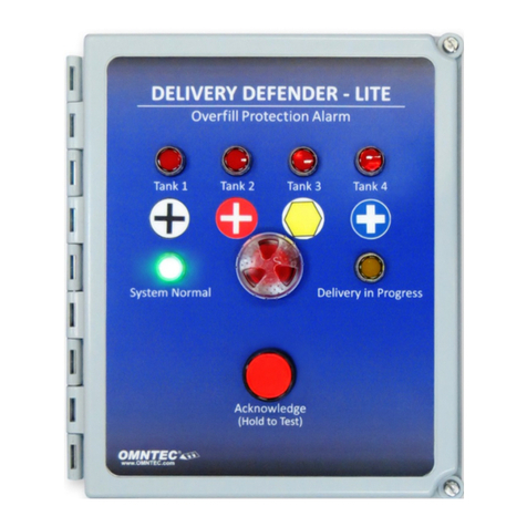
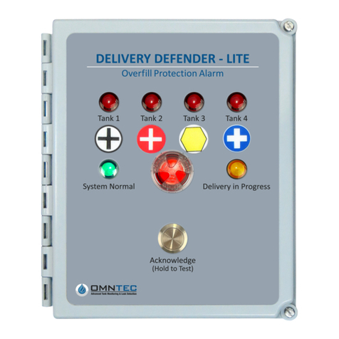
Omntec LU6-BF-4H2L User manual

LU6-BF-4H2L
INSTALLATION GUIDE
SIX CHANNEL ALARM PANEL
Revision 2322
Document No. LU6-BF-4H2L rev2322
1. Open the camera app
2. Focus the camera on
the QR code by gently
tapping the code
3. Follow the instructions
on the screen to view
PDF file
OMNTEC Mfg., Inc. | 2420 Pond Road | Ronkonkoma | NY 11779 | (631) 981-2001 | Email: [email protected] | www.omntec.com

OMNTEC Mfg., Inc., 2420 Pond Road, Ronkonkoma, NY 11779
Phone (631) 981-2001 Fax (631) 981-2007 www.OMNTEC.com
File Name: LU6-BF-4H2L rev2322.docx Page 2 of 17 Rev Date: 5-31-2023
TABLE OF CONTENTS
LU6-BF-4H2L SPECIFICATIONS................................................................................................................. 3
DIMENSIONS FOR MOUNTING AND KNOCKOUTS.................................................................................. 4
LU6-BF-4H2L CONTROLLER CONNECTION DIAGRAM ........................................................................... 6
LS-ASC SENSOR ......................................................................................................................................... 7
LWS SENSOR .............................................................................................................................................. 8
LWF SENSOR .............................................................................................................................................. 9
OWI-BF-1 SENSOR.................................................................................................................................... 10
RA-SERIES REMOTE HIGH-LEVEL ALARM ............................................................................................ 11
LU-SERIES SYSTEM OPERATION AND TEST INSTRUCTIONS ............................................................ 12
LU-SERIES TROUBLESHOOTING PROCEDURES ................................................................................. 13
LOG SHEET................................................................................................................................................ 16
WARRANTY................................................................................................................................................ 17

OMNTEC Mfg., Inc., 2420 Pond Road, Ronkonkoma, NY 11779
Phone (631) 981-2001 Fax (631) 981-2007 www.OMNTEC.com
File Name: LU6-BF-4H2L rev2322.docx Page 3 of 17 Rev Date: 5-31-2023
LU6-BF-4H2L
SIX CHANNEL ALARM PANEL
LU6-BF-4H2L SPECIFICATIONS
AUDIO/VISUAL CONSOLE
Audible Alarm - 95 dB pulsing horn with 30 second
timeout
Red Light - Indicates level alarm for OWI-BF-1 sensors
and leak sensors
Test Button - When pressed will test system lights and
horn
Green Light - Indicates the power is on
Horn Off Button - Silences the audible alarm when
pressed
SENSORS
(4) OWI-BF-1 Ball float level sensor
(2) L-Series Leak sensor
OPTIONAL ACCESSORIES
RA Series Remote annunciator
RLY-RA Series Relay (consult factory)
LABELS
Provided with controlle
r
POWER INPUT
85-125 VAC, 47-440 Hz
16 Watts maximum
POWER TO SENSORS
2 VDC @ 13 mA
RELAY OUTPUT
SPST normally open dry contacts 0.5 AMPS, 120 AC
switches when an alarm condition occurs
WEIGHT DIMENSIONS
6 LBS. (W) 9” x (H) 10.5”
SENSOR CABLE
Shielded 22 AWG UL-E118830 CM
Maximum length 2000 feet
ENCLOSURE OPERATING TEMPERATURE
NEMA 4X -40to 140F
UL LISTED
Intrinsically safe circuits for use in class I group D
hazardous locations when connected in accordance
with control drawings L6

OMNTEC Mfg., Inc., 2420 Pond Road, Ronkonkoma, NY 11779
Phone (631) 981-2001 Fax (631) 981-2007 www.OMNTEC.com
File Name: LU6-BF-4H2L rev2322.docx Page 4 of 17 Rev Date: 5-31-2023
LU6-BF-4H2L
DIMENSIONS FOR MOUNTING AND KNOCKOUTS

OMNTEC Mfg., Inc., 2420 Pond Road, Ronkonkoma, NY 11779
Phone (631) 981-2001 Fax (631) 981-2007 www.OMNTEC.com
File Name: LU6-BF-4H2L rev2322.docx Page 5 of 17 Rev Date: 5-31-2023
1. CONTROL UNIT
The control unit (see pg. 3) should be mounted in a manned area. Route sensor control
cable through conduit from the junction box to the control unit. Sensor control cables
enter the control unit through the output port only. The cables are wired as shown in the
appropriate drawing (see pg. 6). The control unit accepts any possible combination of L-
series sensors.
INPUT POWER HOOKUP
Input power requirements are:
85 – 125 VAC
16 Watts max
47 – 440 Hz
Input power cable should be wired in accordance with all pertinent electrical codes. This
cable should enter the control unit through the input power port only. The power is
hooked up to the power supply and wired as per control drawing. NOTE: EARTH
GROUND TERMINAL MUST BE CONNECTED.
1. REMOTE ANNUNCIATOR OPTION
Mount remote annunciator (see pg. 11) within audio / visual range of the filling operator.
NOTE: the remote must be outside of the HAZARDOUS AREA. Pull appropriate low
voltage wire from the remote to the control unit. See appropriate drawing for wiring
details. Run wires through output port. Connect color coded nuts.
2. SK-4 CONNECTOR SEALING KIT
Make all splices using SK-4 connector kit (supplied)

OMNTEC Mfg., Inc., 2420 Pond Road, Ronkonkoma, NY 11779
Phone (631) 981-2001 Fax (631) 981-2007 www.OMNTEC.com
File Name: LU6-BF-4H2L rev2322.docx Page 6 of 17 Rev Date: 5-31-2023
LU6-BF-4H2L CONTROLLER CONNECTION DIAGRAM
COLOR CODE
CABLES FROM SENSORS TO REMOVABLE SENSOR
INPUT CONNECTORS
1 UNUSED SENSOR #1 OWI-BF-1
95% LEVEL
2 WHITE
3 UNUSED SENSOR #2 OWI-BF-1
75% LEVEL
4 WHITE
5 UNUSED SENSOR #3 OWI-BF-1
50% LEVEL
6 WHITE
7 BLACK FROM SENSOR #1 - #3
8 SHIELD DRAIN
9 BLACK FROM SENSOR #4 - #6
10 SHIELD DRAIN
11 UNUSED SENSOR #4 OWI-BF-1
25% LEVEL
12 WHITE
13 RED SENSOR #5 LEAK SENSOR
14 WHITE
15 RED SENSOR #6 LEAK SENSOR
16 WHITE
WIRES TO OPTION BOARD
WIRES FROM RA-SERIES REMOTE
1 GREEN - HORN
2 RED +HORN
3 BLACK GROUND
4 WHITE SENSOR #1 95% LEVEL
5 ORANGE SENSOR #2 75% LEVEL
6 BLUE SNESOR #3 50% LEVEL
7 BROWN SENSOR #4 25% LEVEL
8 YELLOW SENSOR #5 LEAK SENSOR
9 PURPLE SENSOR #6 LEAK SENSOR
10 UNUSED
11 UNUSED
12 UNSED
120 VAC
WIRES TO POWER SUPPLY
F.G. FIELD GROUND
L LINE
N NEUTRAL
NOTE: To maintain proper shielding, BLACK sensor wires and SHIELD DRAINS should
not be connected togethe
r
at sensors.
SENSOR INPUTS
FRONT KNOCKOUT OPTIONAL OUTPUTS
REAR KNOCKOUT INPUT POWER

OMNTEC Mfg., Inc., 2420 Pond Road, Ronkonkoma, NY 11779
Phone (631) 981-2001 Fax (631) 981-2007 www.OMNTEC.com
File Name: LU6-BF-4H2L rev2322.docx Page 7 of 17 Rev Date: 5-31-2023
LS-ASC SENSOR
NON-PRODUCT DISTINGUISHING OPTIC SENSOR
LS-ASC SPECIFICATIONS
U.L. LISTED 5L04 PRINCIPLES OF OPERATION
Intrinsically safe Class I, Group D Hazardous Locations
when connected in accordance with control drawing
nos. L1, L2, L3, L4, L6, L9
LIQUIDS (ex: fuel, water) – Photo optic
DRY CONDITION – Normally closed light beam
ALARM CONDITION – Opens (refracts) normally closed
light beam
OPERATING TEMPERATURE SENSOR CABLE
-40 TO +140 F Shielded 22 AWG UL-E118830 CM
Maximum length 2000 feet
POWER
2 VDC @ 13 mA RESPONSE TIME
Immediate
WEIGHT
1/2 pound
3/4” NPT NIPPLE
RED
SHIELD
DRAIN
WHITE
BLACK
CABLE LENGTH
12 FEET
PRINCIPLES OF OPERATION
3”
1-5/8”

OMNTEC Mfg., Inc., 2420 Pond Road, Ronkonkoma, NY 11779
Phone (631) 981-2001 Fax (631) 981-2007 www.OMNTEC.com
File Name: LU6-BF-4H2L rev2322.docx Page 8 of 17 Rev Date: 5-31-2023
LWS SENSOR
NON-PRODUCT DISTINGUISHING DOUBLEWALL OPTIC SENSOR
LWS SPECIFICATIONS
U.L. LISTED 5L04 PRINCIPLES OF OPERATION
Intrinsically safe Class I, Group D Hazardous Locations
when connected in accordance with control drawing
nos. L1, L2, L3, L4, L6, L9
LIQUIDS (ex: fuel, water) – Photo optic
DRY CONDITION – Normally closed light beam
ALARM CONDITION – Opens (refracts) normally closed
light beam
OPERATING TEMPERATURE SENSOR CABLE
-40 TO +140 F Shielded 22 AWG UL-E118830 CM
Maximum length 2000 feet
POWER
2 VDC @ 13 mA RESPONSE TIME
Immediate
WEIGHT
1/2 pound
3/4” NPT NIPPLE
RED
SHIELD
DRAIN
WHITE
BLACK
CABLE LENGTH
25 FEET
PRINCIPLES OF OPERATION
3”
1-5/8”

OMNTEC Mfg., Inc., 2420 Pond Road, Ronkonkoma, NY 11779
Phone (631) 981-2001 Fax (631) 981-2007 www.OMNTEC.com
File Name: LU6-BF-4H2L rev2322.docx Page 9 of 17 Rev Date: 5-31-2023
LWF SENSOR
NON-PRODUCT DISTINGUISHING FIBERGLASS TANK DRY INTERSTITIAL SENSOR
LWF SPECIFICATIONS
OPERATING TEMPERATURE PRINCIPLES OF OPERATION
-40 TO +140 F LIQUIDS (ex: fuel, water) – Photo optic
DRY CONDITION – Normally closed light beam
ALARM CONDITION – Opens (refracts) normally closed
light beam
POWER SENSOR CABLE
2 VDC @ 13 mA Shielded 22 AWG UL-E118830 CM
Maximum length 2000 feet
WEIGHT
2 pounds
RESPONSE TIME
Immediate
BLACK
SHIELD
DRAIN
WHITE
RED
LENGTH CUT TO
TANK SPECIFICATION
5/8”
1-5/8”
18”
LIQUID TIGHT
STRAIN RELIEF
SUPPLIED WITH 20 FT
OF CABLE
PRINCIPLES OF OPERATION

OMNTEC Mfg., Inc., 2420 Pond Road, Ronkonkoma, NY 11779
Phone (631) 981-2001 Fax (631) 981-2007 www.OMNTEC.com
File Name: LU6-BF-4H2L rev2322.docx Page 10 of 17 Rev Date: 5-31-2023
OWI-BF-1 SENSOR
FLOAT SENSOR
designed for sewage and sanitary waste applications

OMNTEC Mfg., Inc., 2420 Pond Road, Ronkonkoma, NY 11779
Phone (631) 981-2001 Fax (631) 981-2007 www.OMNTEC.com
File Name: LU6-BF-4H2L rev2322.docx Page 11 of 17 Rev Date: 5-31-2023
RA-SERIES REMOTE HIGH-LEVEL ALARM
SPECIFICATIONS
Audible Alarm 95 dB pulsing horn
Red Light Liquid-high-level alarm
Response Time Immediate
Power Input 12VDC @200mA
maximum from controller
Wire 22 AWG minimum
Weight 1 lb.
RA-1 RA-2 RA-3 RA-4
INTERNAL WIRING COLOR CODE
*Warning Label Placed Here WARNING: LOW VOLTAGE INPUTS ONLY
Note: It is recommended that knockouts be placed in the bottom of enclosure.

OMNTEC Mfg., Inc., 2420 Pond Road, Ronkonkoma, NY 11779
Phone (631) 981-2001 Fax (631) 981-2007 www.OMNTEC.com
File Name: LU6-BF-4H2L rev2322.docx Page 12 of 17 Rev Date: 5-31-2023
LU-SERIES SYSTEM OPERATION AND TEST INSTRUCTIONS

OMNTEC Mfg., Inc., 2420 Pond Road, Ronkonkoma, NY 11779
Phone (631) 981-2001 Fax (631) 981-2007 www.OMNTEC.com
File Name: LU6-BF-4H2L rev2322.docx Page 13 of 17 Rev Date: 5-31-2023
LU-SERIES TROUBLESHOOTING PROCEDURES
FOR LU-SERIES CONTROLLERS WHEN USED WITH ELECTRO-OPTIC SENSORS
9
10
13
SHIELD DRAIN
(
BARE WIRE
)
RED
WHITE
BLACK
12
12
8
4
2
6
5
WARNING: THIS TERMINAL
MUST BE CONNECTE D TO
EARTH GROUND TO
MAINTAIN INTRINSIC SAFETY
F.G.
N
L
OPTION BOARD
REMOVABLE SENSOR
INPUT CONNECTOR
1
8
3
YELLOW
GREY
Be sure the following criteria are met before proceeding:
1. Controllers have their own separate isolated Earth Ground
2. Controllers have their own separate isolated Field Ground
3. The Controller should have 13.8 VDC on the output of the power supply (Across the
yellow-positive and gray-negative wires)
4. 120VAC wires are in their own separate isolated conduit
5. Remote Annunciator wires are in their own separated isolated conduit
6. Sensor wires are in their own separate isolated conduit
7. Sensor shield drain wire is not connected to black wire at sensor splice
8. Black & shield drain are connected to ground at removable input connector
9. Sensor head (prism) is not exposed to any external light (i.e.: sunlight, indoor light, etc)
10. Sensors are free of dirt and debris
11. Sensor extension cables are minimum 3 conductor #22 AWG shielded with drain wire
12. Sensors wires do not exceed 2000 ft.
13. The “POWER” should be illuminated
SHIELD
DRAIN
BLAC
K
WHITE
RED
7
11
Be sure
that the sensor
head (prism) is not
exposed to any external
light (ie: sunlight, indoor
light, etc.)

OMNTEC Mfg., Inc., 2420 Pond Road, Ronkonkoma, NY 11779
Phone (631) 981-2001 Fax (631) 981-2007 www.OMNTEC.com
File Name: LU6-BF-4H2L rev2322.docx Page 14 of 17 Rev Date: 5-31-2023
TROUBLESHOOTING PROCEDURES
SYMPTOM TROUBLESHOOTING PROCEDURE RESULT
“Red Light” does
not come on when
test button is
pressed.
1) Unplug sensors “Removable input
connector” at controller. Does the “red
Light” illuminate?
(YES) controller is functioning.
Proceed to step 2.
(NO) controller is not functioning
(consult factory).
2) Check wiring at removable input
connector. Concentrate on white, black
and shield wire inputs from sensors,
making sure no shorts are present. Re-
plug connector and press test button.
Does the “Red Li
g
ht” illuminate?
(YES) system is functioning
properly.
(NO) Proceed to step 3.
3) Check splice at sensor for moisture or
mis-wire (concentrating on white and
black wires from sensor). Correct
problem and press test button. Does the
“Red Li
g
ht” illuminate?
(YES) problem are in the wire
connections at splice
(NO) sensor is not functioning
properl
y
. Proceed to step 4.
4) Remove sensor from installation,
connect at controller, shroud from light
and press test button. Sensor head
(prism) is not exposed to any external
light (ie: sunlight, indoor light, ect.).
Does the “Red Li
g
ht” illuminate?
(YES) problem in wire run to
sensor. System is functioning
properly.
(NO) The sensor failed (consult
factor
y)
TEST BUTTON HORN OFF BUTTON
HORN
RED LIGHTS
POWER
LU-SERIES Controller

OMNTEC Mfg., Inc., 2420 Pond Road, Ronkonkoma, NY 11779
Phone (631) 981-2001 Fax (631) 981-2007 www.OMNTEC.com
File Name: LU6-BF-4H2L rev2322.docx Page 15 of 17 Rev Date: 5-31-2023
“Red Light”
remains on.
1) Check if sensor is actually in alarm
(submerged)
(YES) correct alarm condition.
(
NO
)
proceed to step 2.
2) Check wiring at removable input
connector concentrating on red, white,
black and shield wire inputs from
sensors. Make sure no open circuits
are present. Re-plug the connector and
press test. Does the “Red Light” stay
on?
(YES) proceed to step 3.
(NO) System is functioning
properly. Problem was in the wire
or connections.
3) Disconnect sensor wires from
removable sensor input connector.
Connect a jumper from the white input
to the black input at the connector.
Make sure all sensor wiring is
disconnected. Does the “Red Light” stay
on?
(YES) Controller is not
functioning properly (consult
factory)
(NO) Controller driver boards are
functioning properly. Proceed to
step 4.
4) Check DC voltage from red input to
black input. Is it 7.5 – 9V DC?
(YES) proceed to step 5
(NO) Controller is not functioning
properl
y
. Consult factor
y
.
5) Check splice at sensor for moisture or
mis-wire. Correct problem. Does the
“Red Light” stay on?
(YES) proceed to step 6.
(NO) If light goes off before
pressing test button and goes on
after pressing test button
System is functioning properly.
Problem was in the connection or
wire.
6) Connect sensor directly to controller.
Make sure sensor head is not exposed
to light during test. Does the “Red Light”
stay on?
(YES) Sensor is not functioning
properly (consult factory)
(NO) Problem is in the wire or
connections.
Horn does not
sound on controller
when the “TEST”
button is pressed.
1) Are any “Red Lights” illuminated on
controller?
(YES) Make sure at least one
input is not in alarm state. Then
proceed to step 2.
(
NO
)
proceed to step 2.
2) Shut down system for 30 seconds.
Turn system back on. Does horn sound
when hitting the “TEST” button?
(YES) Controller is functioning
properly.
(NO) Controller is not functioning
properl
y
. Proceed to step 3.
3) While holding the “TEST” button
down put a voltmeter on the positive and
negative on the back of the horn. Do
you get 13.8 volts +/- 1?
(YES) Your horn does not work.
Replace horn.
(NO) Your horn board is not
workin
g
(
consult factor
y)

OMNTEC Mfg., Inc., 2420 Pond Road, Ronkonkoma, NY 11779
Phone (631) 981-2001 Fax (631) 981-2007 www.OMNTEC.com
File Name: LU6-BF-4H2L rev2322.docx Page 16 of 17 Rev Date: 5-31-2023
LOG SHEET
DATE NAME SYSTEM STATUS SIGNATURE

OMNTEC Mfg., Inc., 2420 Pond Road, Ronkonkoma, NY 11779
Phone (631) 981-2001 Fax (631) 981-2007 www.OMNTEC.com
File Name: LU6-BF-4H2L rev2322.docx Page 17 of 17 Rev Date: 5-31-2023
WARRANTY
The seller OMNTEC Mfg., Inc. warrants to buyer defects when properly installed, and maintained
by user. The seller’s sole obligation is to repair or replace parts found to be defective, or non-
conforming for one year and only after evaluation by factory. The liability of the seller shall not
exceed the price paid for the components found to be defective. The above warranty is exclusive
of all other warrantees whether implied or expressed. Seller assumes no obligation for special or,
indirect damages incurred by user.
All standard tank gauging systems are free of defects when properly installed and maintained by
user. Warranty on tank gauging systems will only be effective after proper documentation has
been submitted by the buyer to OMNTEC Mfg., Inc. The seller’s sole obligation is to repair or
replace parts found to be defective, or non-conforming for one year and only after evaluation by
factory. Technical support must be contacted for a Return Material Authorization (RMA #) prior
to sending any potentially defective parts. The liability of the seller shall not exceed the price paid
for the components found to be defective. The above warranty is exclusive of all other
warrantees whether implied or expressed. Seller assumes no obligation for special or indirect
damages incurred by user.
All standard replacement parts, "add-ons", or spare parts are free of defects when properly
installed and maintained by user. The seller’s sole obligation is to repair or replace parts found
to be defective or non-conforming for 90 days and only after evaluation by factory. The liability
of the seller shall not exceed the price paid for the components found to be defective. The above
warranty is exclusive of all other warrantees whether implied or expressed. Seller assumes no
obligation for special or indirect damages incurred by user.
Equipment not covered by this warranty includes but is not limited to: custom equipment and
control systems.
Table of contents
Other Omntec Security System manuals