3. Loosely assemble two M8 x 16mm Button Head
Socket Screws and T-Nuts in the Camera
Bracket as shown in Step 2.
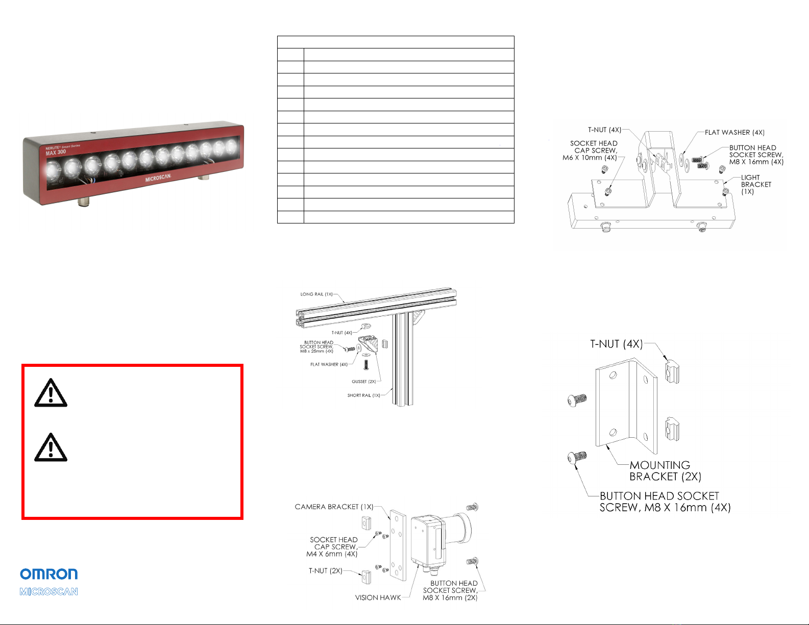
4. Attach the MAX 300 illuminator to the Light
Bracket with the hardware shown below.
Note: The MAX 300 can be mounted with the
connectors oriented opposite of what is shown
below (up vs. down) if required by the application.
5. Loosely assemble four M8 x 16 mm Button Head
Socket Screws, Flat Washers, and T-Nuts in the
Light Bracket as shown in Step 4.
6. Loosely assemble four M8 x 16 mm Button Head
Socket Screws and T-Nuts in the two Mounting
Brackets as shown below.
Kit Contents
1. Attach the Short Rail to the Long Rail using the
two Gussets and the hardware shown below.
Note: T-Nuts must be inserted into the slots in the
rails from the rail ends.
2. Attach the Vision HAWK camera
to the Camera Bracket with the
hardware shown below.
Note: The mounting hole pattern in the
Camera Bracket is not symmetrical. The
Camera Bracket must be positioned as
shown relative to the camera.
MAX 300 Bracket Kit (98-000268-01)
Qty. Description
1Long Rail
1Short Rail
1Camera Bracket
1Light Bracket
2Mounting Bracket
2Gusset
14 T-Nut
3End Cap
10 Button Head Socket Screw M8 x 16 mm
4Button Head Socket Screw M8 x 25 mm
4Socket Head Cap Screw M6 x 10 mm
4Socket Head Cap Screw M4 x 6 mm
8Flat Washer
Quick Start Guide
NERLITE Smart Series
MAX 300 Bracket Kit
(Vision HAWK C-Mount)
P/N 83-9200060-02 Rev A
Caution: Be sure that all
connections are secure BEFORE
applying power. Power down
BEFORE disconnecting cables.
Important: All specified wire
colors apply to Omron Microscan
cables. If non-Omron Microscan
cables are used, it is the customer’s
responsibility to make sure the
illuminator is connected per the
specified connector pin numbers.
Copyright ©2018 Omron Microscan Systems, Inc.


