Omron G8C-501M User manual

A
PPROVEDCHECKEDDESIGNED
G8C-501M
Receiver, RF Keyless Entry System
戸谷 彰信

Table of contents
1. Constitution
of the Radio Frequency Keyless Entry system for vehicle............. 1
2. User’s manual (provisionally) .......................................................................... 2
3. Block diagram ................................................................................................ 3
4. Specification ................................................................................................... 4
5. Features .......................................................................................................... 5
6. Supplement ...................................................................................................
7. PCB
7.1 Circuit diagram ........................................................................................... 6
7.2 Parts layout ................................................................................................. 8
7.3 Printed circuit pattern ................................................................................. 10
7.4 Parts list ..................................................................................................... 12
7.5 Connector ................................................................................................... 14
8. HIC
8.1 Circuit diagram ........................................................................................... 15
8.2 Parts layout ................................................................................................. 16
8.3 Printed circuit pattern ................................................................................. 18
8.4 Parts list ...................................................................................................... 22
9. RF MODULE
9.1 Circuit diagram ........................................................................................... 25
9.2 Parts layout ................................................................................................. 26
9.3 Parts list ...................................................................................................... 28
10. Photographs .................................................................................................... 30

1. Constitution of the Radio Frequency Keyless Entry System for Vehicle
The radio frequency keyless entry system controls door lock/unlock by wireless remote control.
This system consists of 2 components:the TRANSMITTER and the RECEIVER.
The TRANSMITTER, when activated by pressing the appropriate button, sends a signal that
consists of several synchronous codes, unique identification code and security code and function
code.
The second component is the RECEIVER, which is installed in the vehicle.
It works intermittently to reduce the battery exhaustion of the car.
It runs continuously to receive signals completely when it detects the synchronous code.
The user can select the following functions by pressing one of two buttons on the
TRANSMITTER.
BUTTON FUNCTION
LOCK Lock the door
UNLOCK Unlock the door
PANIC Starts sounding the horn and flashing the headlight intermittently
Transmitter
f =313.8〜313.9MHz

2. User’s manual (provisional)
3BUTTON TRANSMITTER (OMRON TYPE:G8D-525M-A6-C)
2BUTTON TRANSMITTER (OMRON TYPE:G8D-525M-A9-C)
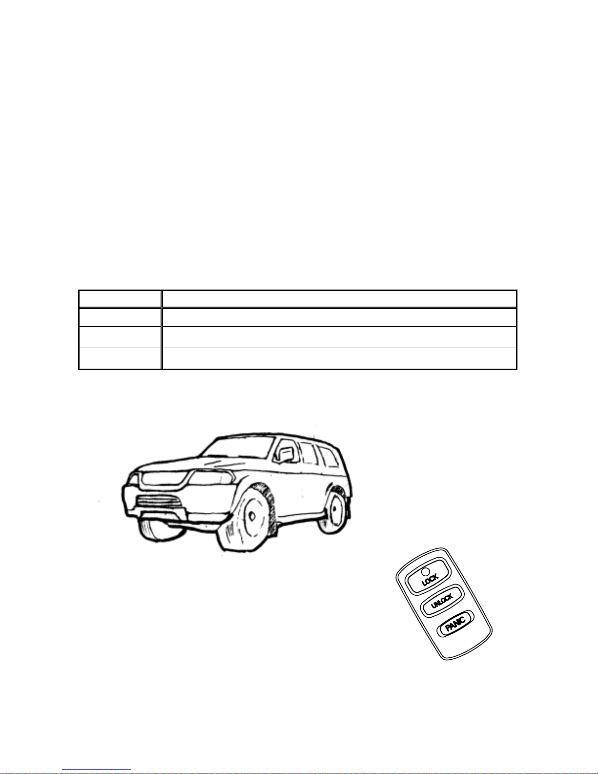
You can control door lock/unlock and panic alarm with the TRANSMITTER.
LOCK
When you press the LOCK button, all the doors will lock.
You cannot lock the doors with the TRANSMITTER if the key is in the key cylinder.
UNLOCK
When you press the UNLOCK button, to begin with, the driver’s door will unlock.
Secondly, if you press it once more continuing the state that driver’s door is UNLOCK,
all the doors will unlock. You cannot unlock the doors with the TRANSMITTER
if key is in the key cylinder. If the doors are not opened within 30 seconds after you unlock
the door with the TRANSMITTER, all the doors will be automatically relocked.
PANIC ALARM
When you press the PANIC button, the vehicle starts sounding the horn and flashing
the head light intermittently. These functions continue for 175 seconds unless any of
the buttons on the TRANSMITTER are pressed.
△CAUTION
The remote control switch (TRANSMITTER) is a precision electronic device.
Therefore please pay attention to the following:
Do not impose shock to the TRANSMITTER.
KeeptheTRANSMITTERdry.
Do not disassemble the TRANSMITTER.
When the TRANSMITTER is opened, avoid getting water and dust, etc
inside it. In addition, do not touch the precision electronic parts.

3. Block diagram
ANT
※
16BIT
CPU
RECEIVE
CIRCUIT
POWER
SOURCE(5V)
data
DOORLOCK
A
CTUATOR
Signal of vehicle status
input
12V (car battery)
data
data
FRONT
ECU
CLOCK
O.S.C
8.00MHz
313.8〜313.9MHz
EEPROM
output DRIVE
CIRCUIT
figure 3.1 Block diagram of the receiver
A
NT
BP
FILTER RF
-AMP MIX
IF
FILTER LOW- Freq
AMP
AMP
COMPAR
ATOR
CPU
O.S.C
figure3.2Block diagram ※RECEIVE CIRCUIT

4. Specification
4.1 CPU
Type MB90F548GLSPFV-GS
Manufacturer: FUJITSU
ROM 128Kbyte
RAM 4Kbyte
Clock frequency 8.00MHz
Clock frequency generation Crystal resonator
Package 100pin LQFP
4.2 EEPROM
Type S93C56AMFN
Manufacturer: Seiko instruments.
Memory 2Kbit
Package 8pin MSOP
4.3 RF Receiver Module
Type G8X-21RX-R
Manufacturer: IAM
Local clock frequency 10.14MHz
Frequency generation Crystal resonator
Modulation Scheme FM
Carrier Detect Sensitivity 3 dBuVemf
4.4 Others
Dimension 187.3mm×80.6mm×39.5mm
Weight 260g
Battery Car Battery (DC 12V)
Operation Voltage , Current DC 12V, 120mA
Operation temperature -30℃~ +75℃

5. Features
5.1 Door lock control
The RECEIVER sends “LOCK”signal to the door-lock actuators when LOCK button on the TRANSMITTER
is pressed. The RECEIVER also sends “UNLOCK”signal to the door-lock actuators when UNLOCK button
on the TRANSMITTER is pressed.
These functions don’t work if the key is in the key cylinder.
5.2 Automatic locking
The RECEIVER sends “LOCK”signal to the door-lock actuators if any of the doors are not opened within
30 seconds after UNLOCK button on the TRANSMITTER is pressed.
This function prevents the key from continuing the state of UNLOCK when the UNLOCK button is pressed
by accident, such as the key is in user’s pockets.
5.3Theft alarm(panic alarm)
The RECEIVER sends signal to the horn circuit and Front ECU when PANIC button on the TRANSMITTER.
Afterward the vehicle starts sounding the horn and flashing the headlight intermittently.
These functions continue for 175 seconds unless any of the buttons on the TRANSMITTER are pressed.
5.4 Battery saving
Because the power source of the receiver is the car battery, it is very important to minimize power
consumption. The RECEIVER (CPU: within RECEIVER) works intermittently to reduce the battery
exhaustion.
6. SUPPLEMENT
G8C-501M is an integrated controller for function of the car, such as door lock (includes the keyless entry ) ,
theft alarm, turn signal-light, interior light, power window timer, ignition key illumination, warning buzzer, etc.
This controller has many input and output signals, some of them are concerned with the keyless entry system.
This document refers only to keyless entry system (not refers to other functions.)
Table of contents
Other Omron Automobile Accessories manuals
Popular Automobile Accessories manuals by other brands

Kolpin Outdoors
Kolpin Outdoors 15-0070 Assembly & owners manual

Rear view safety
Rear view safety RVS-916619P Product manual installation & instructions

VBG
VBG Onspot Mounting instruction/Spare Parts List

Metra Electronics
Metra Electronics 99-7322 installation instructions

Volvo
Volvo 32296522 user guide

ACV
ACV 381114-21-1 installation manual