(15) Use M4 screws and washers to install the switch and actuator.
Tighten the screws with a specified torque. After installing and
commissioning, coat the switch-actuator fixing screws with
tamper-proof varnish or similar compound for locking. Using
anaerobic locking compounds can have a detrimental effect on
the plastic switch case if the compounds contact with the switch case.
Compact Non-Contact Door Switch
INSTRUCTION MANUAL
Type D40Z
English
Precautions for Safe Use
Meaning of Warning Sign
The following warning sign is used in this manual.
Indicates mandatory actions.
Meaning of Alert Symbol
The following alert symbol is used in this manual.
Alert Statements
WARNING
WARNING
Precautions for Safe Use
Precautions for Correct Use
D1 D2 D3 D4
G9SX-NS202
G9SX-NSA222
Total wiring length
100m max.
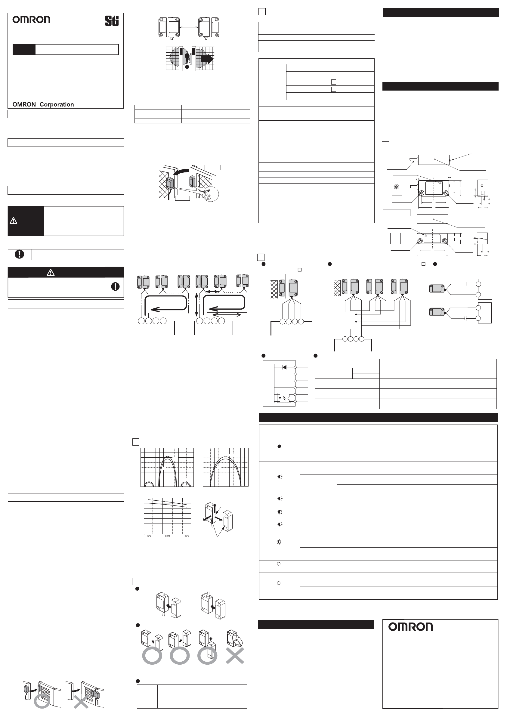
Connection Example
5
Black
Brown
White
Blue
Black
Brown
Black
Brown
Black
Brown
White
Blue
White
Blue
White
Blue
Yellow
Gray
Yellow
Gray
Ratings and Specifications
3
Item
Power consumption (Note 1)
D40Z-1Cڧ
0.5 W max.
Supply voltage 24 VDC +10% / -15%
Operating
distance
(Note 2)
Response time (ON to OFF)
(Note 3)
Ambient humidity
Degree of protection
Material
Mounting method
Tightening torque
5 mm min.
25 ms max.
25 to 85%RH
IP67
Molded PBT
M4 screws
1N .m
Auxiliary output
Photocoupler output
24VDC Load current: 10 mA
Ambient temperature
-10 to +65
°
C
(No freezing or condensation)
Operating time (OFF to ON)
(Note 3)
100 ms max.
(for a 5-mm distance between sensing
surfaces of switch and actuator)
OFF to ON
ON to OFF
Differential travel
Temperature influence
15 mm max.
Note1. Power consumption of loads is not included.
Note2. This is the distance where the switch operates from OFF to ON
when approaching and the distance where the switch operates
from ON to OFF when separating when the switch and actuator
target marks are on the same axis, and the sensing surfaces
coincide.
Note3. The value of Non-contact door switch output is indicated.
Dimensions
4
Performance Levels / Safety Categories
Inspection / Maintenance
• Daily inspection:
1. Check every guard door to see that machine stops
when guard door is opened.
• 6-month inspection:
1. Isolate all power.
2. Check the switch and actuator for proper alignment.
3. Check terminals for proper connections.
4. Check wiring for signs of damage.
5. Before resuming normal machine operation,
check every guard door to see that machine stops
when the guard door is opened.
Fault in power supply
Input (brown/blue)
Fault in Non-contact
door switch output
(black)
Sensing fault
Fault in Non-contact
door switch signal
input (white)
Actuator fault
Note1. Another possible cause is a failure in internal circuit. In this case, replace with a new D40Z.
Yet another possible cause is excessive noise. In this case, check and correct ambient noise environment.
Note2. The case where the guard door is closed (Switch detects actuator) is indicated.
Causes and Corrective Action (Note 1)
LED indicator
Noise or
D40Z failure There may be excessive noise. Check and correct ambient noise environment.
There may be a failure in internal circuit. Replace with a new D40Z.
Invalid actuator may be in a close range to switch.
Use the dedicated actuator.
Another D40Z may be in OFF state.
Check status of another D40Z connected to the white line and the wiring.
Refer to Section 2. Switch and actuator operation and Section 5. Connection Examples.
There may be a failure in actuator. Replace with a new D40Z.
OFF
Red continuously
blinking
Red Solid-ON (Note 2)
Red blinks twice for 2s
Red blinks once for 2s
Red blinks thrice for 2s
Yellow
Blinking
Power supply input may be improperly wired. Check and correct wiring of brown and blue lines.
Refer to Section 5. Connection Examples.
Black line may be shorted to other line. Check and correct wiring of black line if the black line is
shorted to other lines. Refer to Section 5. Connection Examples.
Faulty signal may be input to white line. Check and correct wiring of white line.
Refer to Section 5. Connection Examples.
White line may be disconnected.
Check and correct wiring of white line.
Refer to Section 5. Connection Examples.
Troubleshooting
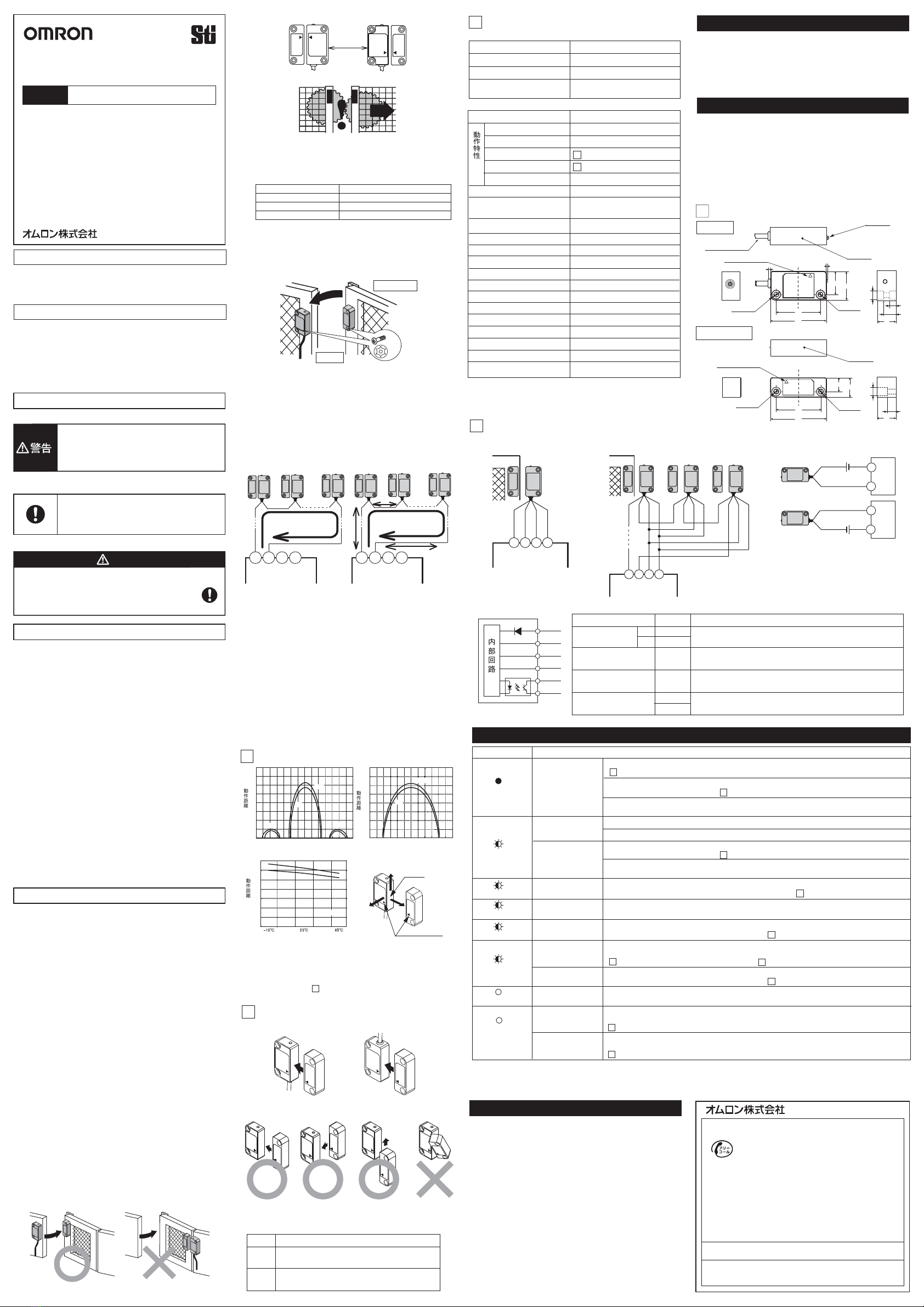
Switch and actuator operation
2Switch and Actuator Mounting Directions
Switch and Actuator Operating Directions
Switch Actuator Switch
Actuator
Detection Ranges (Typical data)
1
XSensing surface
(12) When installing two or more adjacent switches, keep a distance
of at least 50 mm from one another.
50mm Min.
Switch
Actuator
LED Display
LED color
Status
ON: Switch does NOT detect actuator.
Blinking: Switch detects a fault.
ON: Switch detects actuator.
Blinking: Switch detects actuator,
and non-contact door switch signal input is in OFF state.
RED
YELLOW
Metallic material Operating distance
Iron Approximately 75% of the original value
Aluminum Approximately 85% of the original value
Stainless steel Approximately 85% of the original value
ZY
Target mark
D1 D2 D3 D4
G9SX-NS202
G9SX-NSA222
D1 D2 D3 D4
G9SX-NS202
G9SX-NSA222
Single switch connection
with G9SX-NS Multiple switch connection with G9SX-NS Wiring example of
auxiliary output
Maximum 30 switches connectable in series
Note 1. Maximum auxiliary output current is 10mA.
Incorrect wiring may damage the auxiliary output circuit.
Note 2. Refer to the D40Z catalog for other types of wiring.
24VDC
PLC, etc
24VDC
Internal Circuit
brown
white
black
gray
yellow
blue
Signal Name
Color of
Conductor
Brown
Blue
White
Black
Yellow
Gray
+
-
Non-contact door switch
power input
Non-contact door switch
signal input
Non-contact door switch
Output
Description of Operation
Power supply for D40Z
To set non-contact door switch output in ON state,
non-contact door switch signal input must be in ON state.
Auxiliary monitoring
Output Output status depends on status of actuator.
When a fault is detected, turns into OFF state regardless of actuator status.
Output status depends on statuses of actuator and
non-contact door switch signal input.
EU Declaration of Conformity
Standards
Original instructions
See 1 Detection ranges
See 1 Detection ranges
Thank you for purchasing D40Z Compact Non-contact
Door Switch.
Please read and understand this manual before using
the products.
Keep this manual ready to use whenever needed.
Only qualified person trained in professional electrical
technique should handle D40Z.
Please consult your OMRON representative if you have
any questions or comments.
Make sure that information written in this document are
delivered to the final user of the product.
OMRON declares that D40Z is in conformity with the
requirements of the following EU Directives:
Machinery Directive 2006/42/EC
EMC Directive 2004/108/EC
D40Z is designed and manufactured in accordance with the
following standards:
EN954-1 Cat. 4 (with G9SX-NSڧ)
EN ISO13849-1:2008 Cat. 4 PL e (with G9SX-NSڧ),
IEC/EN61508 SIL3 (with G9SX-NSڧ)
IEC/EN60947-5-3 PDF-M (with G9SX-NSڧ),
IEC/EN61000-6-4, EN1088,
UL508, CAN/CSA C22.2 No.14
Indicates a potentially hazardous
situation which, if not avoided, will result
in minor or moderate injury, or may result
in serious injury or death.
Additionally there may be significant
property damage.
Machine may start operating and may result serious
injury or death.
Do not put the actuator close to the switch when the
door is opened.
(1) Disconnect D40Z from power supply when wiring D40Z. Failure to
do so may cause unexpected operation of devices connected to
D40Z.
(2) Do not operate D40Z with flammable or explosive gas.
(3) Incorrect wiring may lead to loss of safety function. Wire
conductors correctly and verify the operation of D40Z before using
the system in which D40Z is incorporated.
(4) Auxiliary monitoring output is NOT safety output. Do not use
auxiliary monitoring output individually for any safety function. Such
incorrect use causes loss of safety functions of D40Z and its
relevant systems.
(5) After installation of D40Z, qualified personnel should verify to see
that the installation, inspection, and maintenance are properly
performed. The qualified personnel should be qualified and
authorized to secure the safety on each phases of design,
installation, running, maintenance and disposal of system.
(6) Qualified personnel, who are familiar to the machine in which
D40Z is to be installed, should conduct and verify the installation.
(7) Be sure to inspect D40Z daily and every 6 months. Otherwise,
serious injury may possibly occur due to a system malfunction.
(8) Do not dismantle, repair, or modify D40Z. Doing so may lead to
loss of its safety functions.
(9) Do not apply DC voltages exceeding the rated voltages, nor any
AC voltages to D40Z.
(10) Use a DC supply satisfying the requirements given below to
prevent electric shock.
- A DC power supply with double or reinforced insulation, for
example, according to IEC/EN 60950 or EN 50178, or a
transformer according to IEC/EN 61558.
- A DC supply satisfying the requirements for class 2 circuits or
limited voltage/current circuits stated in UL 508.
(11) Use only appropriate components or devices complying with
relevant safety standards corresponding to the required
performance level and safety category. Conformity to
requirements of the performance level and safety category must
be determined as an entire system. It is recommended to consult
a certification body regarding assessment of conformity to the
required safety level.
(1) Always use D40Z with dedicated actuator and dedicated controller
to comply with the requirements of EN ISO 13849-1.
(2) Handle with care
Do not drop D40Z to the ground or expose to excessive vibration or
mechanical shocks. Doing so may damage D40Z and cause failure.
(3) Conditions of storage and usage
Do not store or use D40Z under the following conditions. Doing so
may damage D40Z and cause failure.
1) In direct sunlight
2) At ambient temperatures out of the range of -10 to +65
°C
3) At relative humidities out of the range of 25% to 85% or under
such temperature change that causes condensation.
4) In corrosive or combustible gases
5) With vibration or mechanical shocks out of the rated values.
6) Under splashing of oil or chemicals
7) In the atmosphere containing dust, saline or metal powder.
8) Where steel scrap or metal powder may fall directly to D40Z.
(4) Do not use D40Z at altitudes over 1,000 meters.
(11) Be sure to install D40Z switch and actuator in such as appropriate
distance that does not create a gap accessible to the hazard.
(13) Be sure that the machine is stopped whenever the guard door
is open.
(18) D40Z is a class A product. In residential areas D40Z may cause
radio interference, in which case the user may be required to take
adequate measures to reduce interference.
(19)
D40Z may not function properly in surrounding environment with strong
electromagnetic equipment such as RFID system, proximity sensor, motor,
inverter, and switching power supply. If you use D40Z near such equipment,
be sure to verify effects of such equipment on D40Z before using.
(20) Handle cables with care:
1) For bending cables, it is recommended to bend them with a
radius of bend no less than six times the cable outer diameter.
2) Do not apply a tensile strength of 50N or greater to the cables.
(21) To determine safety distance to hazards, take into account the
delay of non-contact door switch output caused the response time.
(22)
If there is any machine that has a large surge current (e.g., a motor) near
D40Z, connect a surge absorber to D40Z between the blue and the other
cables (white, black, and brown), respectively, and between the yellow and
the gray cables. Suggested surge absorber's specification is as follows:
- Peak pulse power: 600W (10/1000ȣs) or more
(Per IEC61000-4-5(surge immunity))
- Breakdown voltage: 27-33V
Note1. Operating distance means the distance of the sensing surfaces
between the switch and actuator.
Note2. Above graph is only for reference temperature at 23°C.
Actual operating distance may vary depending on the
surrounding metals or temperature.
Note3. Surfaces other than the sensing surfaces of the switch and
actuator may activate the detection. Be sure to install the switch
and actuator so that the sensing surfaces oppose one another,
according to the following "2. Switch and Actuator Operation"
D40Z can achieve the corresponding performance levels and
categories up to PL e and Category 4 per EN ISO 13849-1 by
the combined use with the controller G9SX-NSڧ.
Note that the performance levels and categories are based on
the example circuits that we recommend. This does NOT
mean that the combination of D40Z and G9SX-NSڧcan
always achieve the performance levels and categories under
all the similar conditions and situations.
UL does not provide ULcertification for any functional safety
rating or aspects of the D40Z device.
Conformity to the performance levels and categories must be
assessed as a whole system. When using D40Z and
G9SX-NSڧfor performance levels and safety categories,
perform the installation, inspection, and maintenance properly,
and be sure to confirm the conformity as a whole system.
Internal connection
ە30 or less D40Z connected
Item D40Z-1Cڧ
ەRatings
ەSpecification and Performance
Wiring
Power supply to D40Z may be insufficient.
Check the power-supply voltage of D40Z fills ratings. Refer to Section 3. Ratings and Specification.
The wiring length or size of the wire may not be to the specification.
Check the wiring length and size of the wire. Refer to Precautions for Correct Use.
Power supply to D40Z may be insufficient.
Check the power-supply voltage of D40Z fills ratings. Refer to Section 3. Ratings and Specification.
The wiring length or size of the wire may not be to the specification.
Check the wiring length and size of the wire. Refer to Precautions for Correct Use.
Fault in power supply
Input (brown/blue)
Fault in Non-contact
door switch signal
input (white)
OFF state
of another D40Z
Yellow Solid-ON
(Note 3)
Note3. The case where the system stops though the guard door is closed (Switch detects actuator) is indicated.
Fault in Non-contact
door switch signal
input (white)
Fault in Non-contact
door switch output
(black)
White line connected to D1 terminal of G9SX-NSڧmay be shorted to other line.
Check and correct wiring of white line connected to D1 terminal of G9SX-NSڧ
if the white line is shorted to other lines. Refer to Section 5. Connection Examples.
Black line connected to D2 terminal of G9SX-NSڧmay be disconnected.
Check and correct wiring of black line connected to D2 terminal of G9SX-NSڧ.
Refer to Section 5. Connection Examples.
Weight (D40Z-1C5) Switch: approx. 175 g
Actuator: approx. 20 g
D1 D2 D3 D4
G9SX-NS202
G9SX-NSA222
Total wiring length
200m max.
ە15 or less D40Z connected
(Note)
(Note)
(Note)
Note. The wiring length between the products must be 100m max.
(17) Use cables of a total length of 100m max. to connect multiple
D40Z switches. However, the total length of 200m max. is possible
depending on the number of D40Z switches connected. The
supply voltage to D40Z may decrease by the voltage drop
depending on the cable or the wiring configuration. Check the
power-supply voltage is in the rated range.
(5) Do not use to connect other switches or sensors to the wire
conductors of D40Z.
(6) Disconnect D40Z and the controller connected to D40Z from power
supply when replacing D40Z. Failure to do so may cause
unexpected operation of devices connected to D40Z.
(7) Keep D40Z from solvent such as alcohol, thinner, trichloroethane or
gasoline. Such solvents make the marking on D40Z illegible and
cause deterioration of parts.
(8) Do not use D40Z in the magnetic field of 1.5 mT or more, otherwise
D40Z may not function properly.
(9) Do not use D40Z in the water or continuous water exposure
environment, otherwise water may leak into D40Z. (An enclosure of
IP67 rating, which D40Z is rated, protects against temporary
immersion in water.)
(10) Do not use D40Z switch or actuator as a stopper. Use a stopper to
protect the switch and the actuator. Keep a distance of at least
1mm between the switch and the actuator.
(16) Wiring:
1.Use conductors of the following sizes to wire D40Z:
-Stranded wire: 0.2 to 2.5mm
2
AWG24 to AWG12
-Solid wire: 0.2 to 2.5mm
2
AWG24 to AWG12
2.
When not using auxiliary output, cut off the unused conductors and
protect by insulating-taping to prevent contacting with other terminals.
3.When you use an additional cable of 20m or longer, use a
multiconductor cable to group the white, black, brown, and
blue lines together.
(Note)
Note. When using the operating direction along the sensing surface,
be sure to install the switch and actuator so as not to be affected
by the side lobe.
COM
IN
PLC, etc
COM
IN
Repeat accuracy (max.)s10% of operating distance at 23Υ
As per IEC/EN 60947-5-3
Electromagnetic compatibility
Pollution degree 3
Dielectric strength
(Between all conductive parts
and switch case) 1000 VAC for 1min
Insulation resistance
(Between all conductive parts
and switch case) 50 Mohm min.
(at 500 VDC megger)
Shiokoji Horikawa, Shimogyo-ku, Kyoto, 600-8530 JAPAN
OMRON Corporation (Manufacturer)
OMRON EUROPE B.V. (Importer in EU)
Wegalaan 67-69, NL-2132 JD Hoofddorp THE NETHERLANDS
PHONE 31-2356-81-300 FAX 31-2356-81-388
OMRON SCIENTIFIC TECHNOLOGIES INC.
6550 Dumbarton Circle, Fremont CA 94555-3605 U.S.A
PHONE: 1-510-608-3400 FAX: 1-510-744-1442
OMRON ASIA PACIFIC PTE. LTD.
438A Alexandra Road # 05-05/08,
Alexandra Technopark Singapore 119967 SINGAPORE
PHONE: 65-6-835-3011 FAX: 65-6-835-2711
Note: Specifications subject to change without notice.
OMRON (CHINA) CO., LTD.
Room 2211, Bank of China Tower, 200 Yin Cheng Zhong Road,
PuDong New Area, Shanghai, 200120, China
PHONE: 86-21-5037-2222 FAX: 86-21-5037-2200
Suitability for Use
OMRON shall not be responsible for conformity with any
standards, codes, or regulations that apply to the
combination of the products in the customer's application or
use of the product.
Take all necessary steps to determine the suitability of the
product for the systems, machines, and equipment with
which it will be used. Know and observe all prohibitions of
use applicable to this product.
NEVER USE THE PRODUCTS FORAN APPLICATION
INVOLVING SERIOUS RISK TO LIFE OR PROPERTY
WITHOUT ENSURING THAT THE SYSTEM AS A WHOLE
HAS BEEN DESIGNED TO ADDRESS THE RISKS, AND
THAT THE OMRON PRODUCT IS PROPERLY RATED
AND INSTALLED FOR THE INTENDED USE WITHIN THE
OVERALL EQUIPMENT OR SYSTEM.
Vibration resistance
Frequency: 10 to 55 to 10Hz
Amplitude: 0.75mm half amplitude
Mechanical shock resistance 300m/s
2
Min.
(14)
Installing the switch and actuator on a metallic material may affect the
operating distance. In addition, any instruments nearby that generate strong
radio waves or magnetic fields may affect the operating distance via the
metal. Do not install the switch and actuator directly on a metallic material.
If installation on a metallic material is necessary, be sure to check the effect
on the operating distance before use. Reference values for the effects of
installation on a metallic material.
It is recommended that the switch and actuator unit be separated
at least 10 mm from any metal parts or metallic materials.
M4
1N.m
21.5
38
48
25
20
16 10.5
5.5
(7.2 dia.)
38
48
17
12
16 7
(7.2 dia.)
Sensing surface
Sensing surface
Switch
Actuator
(mm)
(mm)
Cable diameter
: 4.2 dia.
Indicator
Target mark
Target mark
Two. 4.2 dia.
Two. 7.2 dia.
Two. 4.2 dia. Two. 7.2 dia.
Operating Distance Y (mm)
Distance from the target mark on the switch X (mm) Distance from the target mark on the switch Z (mm)
Temperature Influence
Operating Distance Y (mm)
Operating Distance Y (mm)
㻜
㻞
㻠
㻢
㻤
㻝㻜
㻝㻠
㻝㻢
㻝㻞
㻙㻟㻡 㻙㻟㻜 㻙㻞㻡 㻙㻞㻜 㻙㻝㻡 㻙㻝㻜 㻙㻡 㻜 㻡 㻝㻜 㻝㻡 㻞㻜 㻞㻡 㻟㻜 㻟㻡
㻜
㻞
㻠
㻢
㻤
㻝㻜
㻝㻠
㻝㻢
㻝㻞
OFF
ON
OFF
ON
㻙㻟㻜 㻙㻞㻡 㻙㻞㻜 㻙㻝㻡 㻙㻝㻜 㻙㻡 㻜 㻡 㻝㻜 㻝㻡 㻞㻜 㻞㻡 㻟㻜
Side lobe Side lobe
㻜
㻞
㻠
㻢
㻤
㻝㻜
㻝㻠
㻝㻞
OFF
ON
X=0, Z=0
2137840-7C