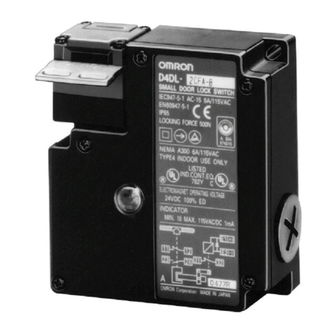
Omron D41L User manual

1
High-Coded Guard Lock Safety Door Switch
D41L
Keep your machines hygienic
• Tamper-proof safety door switch to prevent human error
• Hygienically designed switch
Unique locking mechanism prevents water
and foreign matter from collecting
Smooth surface leaves no wiping unevenness
• Complies with ISO 14119 (Type 4/High Coded),
ISO 13849-1 (PLe)
• ECOLAB certified
Identical mounting for left and right hinged doors
Features
Refer to Safety Precautions on page18
Large actuator tolerances
• Actuator tolerance in
longitudinal direction ± 3.5 mm,
lateral direction ± 2.0 mm
Easy latching force adjustment
• The latching force can be increased
from 25 N to 50 N simply
by turning the star handle 180°.
• Position I: approx. 25 N,
Position II: approx. 50 N
LED display
• Smart diagnostic
by means of 3-color LED's
• LED red: Fault
LED yellow: Status
LED green: Power
For the most recent information on models that have been certified for
safety standards, refer to your OMRON website.
*The actuator is sold separately.
±3.5 mm
±2.0 mm
A high-coded safety switch is defined as one where a sensor is paired with a high level coded actuator for which more than 1,000 variations are
available.

D41L
2
Model Number Structure
Model Number Legend
Safety Door Switch
Sensor
Actuator
D41L - @ @ D@ @ - N2
(2) (3) (4) (5) (6)
(1) Model
L: Guard Lock
(2) Coding level / Teaching limitation
1: High (Individual coding)
2: High (Individual coding, No limitation)
(3) OSSD configuration
Y: Guard monitoring AND lock monitoring
Z: Only guard monitoring
(4) Diagnosis output
D: With diagnosis output
(5) Lock/release logic
A: Power to unlock (Mechanical lock)
G: Power to lock (Solenoid lock)
(6) Release type
Blank: Manual release
E: Emergency exit
(7) Connector
N2: M12
(7)
(1)
D41L - A 1
(2)
(1)
(1) Model
L: Guard Lock
(2) Actuator type

D41L
3
Ordering Information
List of Models
Sensors
Actuator (Sold separately)
Accessory (Sold separately)
Connecting cables
Mounting
Classification
(Lock and Release) Appearance Coding level /
Teaching limitation OSSD configuration Emergency
exit Model
Power to unlock
(Mechanical lock)
High
(Individual coding) Only guard monitoring - D41L-1ZDA-N2
High
(Individual coding,
No limitation)
Only guard monitoring - D41L-2ZDA-N2
High
(Individual coding)
Guard monitoring AND
lock monitoring -D41L-1YDA-N2
High
(Individual coding,
No limitation)
Guard monitoring AND
lock monitoring -D41L-2YDA-N2
High
(Individual coding,
No limitation)
Guard monitoring AND
lock monitoring
Emergency
exit D41L-2YDAE-N2
Power to lock
(Solenoid lock)
High
(Individual coding) Only guard monitoring - D41L-1ZDG-N2
High
(Individual coding,
No limitation)
Only guard monitoring - D41L-2ZDG-N2
High
(Individual coding)
Guard monitoring AND
lock monitoring -D41L-1YDG-N2
High
(Individual coding,
No limitation)
Guard monitoring AND
lock monitoring -D41L-2YDG-N2
High
(Individual coding,
No limitation)
Only guard monitoring Emergency
exit D41L-2ZDGE-N2
Appearance Name Features Model
Actuator 3 different directions of actuation D41L-A1
Appearance Name Specifications Cable length Model
Connecting cables
with Connector M12
Connecting cables
with Connector (M12) (female),
8-pole – 8 x 0.25mm2, straight,
IP69
5 m D41L-8P5-CFM12-905M
10 m D41L-8P5-CFM12-910M
Appearance Name Application Model
Mounting plate For Sensor D41L-MP
Mounting set For Actuator D41L-MS

D41L
4
Standards Certification
EU Declaration of Conformity
• Machinery Directive
•REDirective
•RoHSDirective
• WEEE Directive
Dispose in accordance with applicable regulations.
Standards
• EN ISO 13849-1: PL e Category 4
• EN 60947-5-3
• IEC 61508
• EN 300 330
• EN ISO 14119
UL Certification
• UL508
• CAN/CSA C22.2 No.14
Regions where D41L can be used
The product can be used in Japan, the United States of America, Canada, EU member states, the United Kingdom, and People's Republic of China.
The use in other countries may conflict with radio laws of the countries.

D41L
5
Ratings and Specifications
Model D41L
Technical
Detection method RFID
Frequency band 125 kHz
Transmitter output -6 dBm max.
Interlock type (ISO 14119) Type 4
Coded level (ISO 14119) D41L-1: High (individual coding)
D41L-2: High (individual coding, No limitation)
Actuator D41L-A1
Response time (ON to OFF) 100 ms max.
Response time (input) 1.5 ms max.
Risk time 200 ms max.
Startup time 5 s max.
Typical operating distance (Sn)
(IEC 60947-5-3) 2 mm
Assured operating distance (Sao)
(IEC 60947-5-3) 1 mm
Assured switch-off distance (Sar) 20 mm
Electrical
Supply voltage (Ue) 24 VDC (-15%/+10%)
(stabilized PELV-power supply)
Current consumption (Io) < 0.1 A
Overvoltage category III
Pollution degree 3
Operating current device with magnet switched on Average: <0.2 A
Peak: 0.35 A/200 ms
Magnet switch on time (ED) 100%
Conditional short-circuit current 100 A
External device fuse rating 2 A(T)
Safety input
Switching thresholds -3 V to 5 V (low)
15 V to 30 V (high)
Current consumption per input 5 mA / 24 V max.
Accepted test pulse duration on input signal 1.0 ms max.
Test pulse interval ≥100 ms
Safety output
(OSSD)
Switching element PNP type, short-circuit proof
Utilization category DC-12: 24 VDC (Ue)/0.25 A (Ie)
DC-13: 24 VDC (Ue)/0.25 A (Ie)
Rated operating current (Ie) 0.25 A
OFF-state leakage current (Ir) 0.5 mA max.
Voltage Drop (Ud) 4 V max.
Short-circuit monitoring Yes
Test pulse duration 0.3 ms max.
Test pulse interval 1,000 ms
Auxiliary output
Switching element PNP type, short-circuit proof
Utilization category DC-12: 24 VDC (Ue)/0.05 A (Ie)
DC-13: 24 VDC (Ue)/0.05 A (Ie)
Rated operating current (Ie) 0.05 A
Voltage drop (Ud) 4 V max.
Solenoid
Switching thresholds -3 to 5 V (low)
15 to 30 V (high)
Power consumption 10 mA/24 V
Magnet switching-on time 100%
Accepted test pulse duration on input signal 5.0 ms max.
Test pulse interval 40 ms min.

D41L
6
*1. Refer to Connection on page 10 for connection specifications with the Safety controller.
Mechanical
Protection class III
Switching frequency 0.5 Hz max.
Rated insulation voltage (Ui) 32 VDC
Rated impulse withstand voltage (Uimp) 0.8 kV
Minimum operating current (Im) 0.5 mA
Fixing screws 2 × M6
Tightening torque of fixing screws 6 to 7 N·m
Latching force 25 N/50 N
Guard door weight 5 kg max.
Angular misalignment between safety door switch and actuator 2° max.
Holding force (Fzh) (min.) 1,150 N
Operating speed 0.5 m/s max.
Mechanical durability 1,000,000 operations min.
Mechanical durability (when used as door stop) 50,000 operations min.
Material Fiberglass reinforced thermoplastic self-digestion (Enclosure)
Weight Unit: <580 g, Package: <650 g
Environmental
Ambient operating temperature 0 to 60 °C
Ambient storage temperature (including during transportation) -10 to 90 °C
Ambient operating humidity 93% max. (non-condensing, non-icing)
Degree of protection (IEC 60529) IP66, IP67 and IP69
Vibration resistance 10 to 150 Hz, amplitude 0.35 mm
Shock resistance 30 g/11 ms
Connection
Series connection 31 max. *1
Cable lengths 70 m max. (between switch and power supply)
Connection Connector plug M12, 8-pole
Model D41L

D41L
7
Safety classification information
Note: 1. The actuation of the interlock must be compared with the external OSSD enabler. If a shut-down now occurs due to an unintentional
unlocking this is detected by an external diagnostic.
2. The safety consideration of the guard locking function only applies for monitored safety door switch D41L-@Y.
3. If for a certain application the power to unlock type of a safety door switch cannot be used, then for this exception the power-to-lock type
of a safety door switch can be used if additional safety measure need to be realized that have an equivalent safety level.
4. The safety analysis of the guard locking function refers to the component safety door switch as part of the complete system.
In the event of a fault resulting in the unlocking of the guard locking, this is detected by the safety outputs Y1/Y2 of the safety door switch
switch off. When such a fault occurs the protection equipment may open immediately, just once, before the safe condition of the machine
is reached. The system reaction of category 2 allows that a fault can occur between tests causing the loss of the safety function which
is detected by the test.
5. If multiple safety door switches are involved in the same safety function, the PFH values of the individual components must be added.
UL
This device is intended to be powered by a Listed Limited Voltage, Limited Current or Class 2 source.
This device shall be powered with the use of a Listed (CYJV) cable/connector assembly rated 24 Vdc, 0,8 A minimum.
FCC
This device complies with part 15 of the FCC Rules and contains license-exempt transmitter(s)/receiver(s) that comply with Innovation, Science
and Economic Development Canada’s license-exempt RSS(s): Operation is subject to the following two conditions:
1. This device may not cause harmful interference, and
2. this device must accept any interference received, including interference that may cause undesired operation.
This device complies with the Nerve Stimulation Exposure Limits (ISED RSS-102) for direct touch operations. Changes or modifications not
expressly approved by OMRON Corporation could void the user‘s authority to operate the equipment.
Safety classification (interlocking function)
Standard ISO 13849-1, IEC 61508, IEC 62061
PL e
DC 99%
Safety Category 4
PFH 5.2 x 10⁻¹⁰
PFD 4.5 x 10⁻⁵
SIL Suitable for SIL3 applications
Mission time 20 years
Safety classification (guard lock function)
Standard ISO 13849-1, IEC 61508, IEC 62061
PL d
DC 99%
Safety Category 2
PFH 2.0 x 10⁻⁹
PFD 1.8 x 10⁻⁴
SIL Suitable for SIL2 applications
Mission time 20 years

D41L
8
Structure and Nomenclature
Sensor and Actuator
1. High degree of protection against defeating due to the coded RFID sensor (also available with individual coding)
2. Dampener for door stop - saves costs: no additional mounting parts required
3. Star handle - adjustable latching force - 25 N or 50 N
4. Mounting hole for M6 screws
5. Connector plug M12, 8-pole
6. Manual release
7. LED display
8. Triangular (both sides) for installation of the emergency exit or the emergency release lever.
9. Lever for emergency exit or emergency release
Three actuating directions
(2)
(1)
(3)
(4)
(5)
(5) (8) (9)
(6) (7)
Emergency exit (D41L-@@D@E-N2)
Actuation from the side Actuation from the rear side Actuation from the front

D41L
9
Connection
Pin assignment
Wiring Examples
The application examples shown are suggestions. They however do not release the user from carefully checking whether the safety door switch
and its set-up are suitable for the individual application.
The power supply for the safety door switch must provide protection against permanent overvoltage. To that effect, stabilized PELV supply units
must be used. The safety outputs can be directly connected in the safety circuit of the control system. For applications of PL e / safety category 4
in accordance with ISO 13849-1, the safety outputs of safety door switch or safety door switch of the chain must be connected to a safety controller
or safety relay unit of the same Safety Category.
If the safety door switch is connected to the safety input of a safety controller or safety relay unit, the controller must have a dual-channel monitoring
time of at least 100 ms and the accepted test pulse duration of at least 1 ms. Also, the cross-wire-short monitoring function must be disabled.
D41L series connection example
When connecting multiple safety door switches in series, apply 24 VDC to safety inputs X1 and X2 on the Nth unit, as shown in the figure below.
Connect safety outputs Y1 and Y2 to safety inputs X1 and X2 of the following safety door switch.
Connect safety outputs Y1 and Y2 of the first unit to the safety controller or safety relay unit.
Connect the auxiliary output to the PLC, etc.
When connecting a single safety door switch to the safety controller or safety relay unit, apply 24 VDC to safety inputs X1 and X2 in the same
manner as the Nth unit shown below, and then connect safety outputs Y1 and Y2 to the safety controller or safety relay unit.
Function
Pin configuration of
the connector Color codes of the
OMRON’s connectors
D41L-8P5-CFM12-9@@M
A1 Ue1WHITE
X1 Safety input 1 2BROWN
A2 GND 3GREEN
Y1 Safety output 1 4 YELLOW
OUT Auxiliary output 5GRAY
X2 Safety input 2 6PINK
Y2 Safety output 2 7BLUE
IN Solenoid control 8RED
5
8
4
3
2
1
7
6
1
3
256 8
X1
4
Y1
IN
X2
7
Y2
OUT
24V
GND
X1
Y1
IN
X2
Y2
OUT
24V
GND
X1
Y1
IN
X2
Y2
OUT
24V
GND
1
3
256 847 1
3
256 847
Nth D41L N-1st D41L 1st D41L
Terminal block,
etc.
Safety
outputs
between switch and power supply
PLC, etc.
PLC, etc.
PLC, etc.
PLC, etc.
IN1
IN2
24 VDC
GND
Safety
Controller
PLC, etc. PLC, etc.

D41L
10
Safety controller settings
Combination with a safety relay unit
*Refer to the instruction manual or user’s manual of each product for how to extend the wiring.
OMRON’s
safety controller
NX-SL and NX-SI GI-SMD/SID G9SP
Input device
setting
Input device
Semiconductor Output for
Dual Channel Equivalent
Semiconductor Output for
Dual Channel Equivalent
Dual Safety Semiconductor Output
(Equivalent)
Discrepancy
time
Set discrepancy time to
100 ms or more
NX-Series
Safety Control Unit User's Manual
Refer to the Dual Channel Evaluation
in No.Z930.
Set discrepancy time to
100 ms or more
GI-S series
Safety I/O Terminal User's Manual
Refer to the Dual Channel Evaluation
in No.Z400.
Example
Set discrepancy time to
0 (disabled) or 100 ms or more
G9SP series
Safety Controller User's Manual
Refer to the Dual Channel Evaluation
in No.Z922.
Example
Filtering out
test pulses
Set input filter ON->OFF delay time
to 1 ms or more
NX-Series
Safety Control Unit User's Manual
Refer to the Input Filters
in No.Z930.
Example
Set input filter ON->OFF delay time
to 1 ms or more
GI-S series
Safety I/O Terminal User's Manual
Refer to the Input Filter Function
in No.Z400.
Example
Set input filter OFF delay time to
1 ms or more
G9SP series
Safety Controller User's Manual
Refer to the Input Filters
in No.Z922.
Example
OMRON’s safety relay unit
G9SA G9SE G9SB G9SX
Input device
Safety-door switch D41L Connectable Not connectable Connectable Connectable

D41L
11
Release
Manual Release
For the machine set-up, the safety door switch can be unlocked in a de-energized condition.
The safety door switch is unlocked by turning the manual release in the position (unlock).
The normal locking function is only restored after the manual release has been returned to its original position (lock).
After being put into operation, the manual release must be sealed by means of the seal, which is included in delivery.
Emergency exit (D41L-@@D@E-N2)
To activate the emergency exit, turn the red lever in the direction of the arrow to the end stop. The safety outputs switch off and the guard system
can be opened. The blocked position is cancelled by turning the lever in the opposite direction. In the unlocked position, the guard system is
secured against unintentional locking.
With variants that have emergency-exit, the red lever is included with delivery.
The lever should be fastened to the position intended with the supplied screws before first being used.
The lever should be installed on the unlocking triangle in such a way that the arrow on the triangle and the lever pivot are congruent. The installation
of the lever is possible on both sides.
The opposite is to be sealed with the seal included with delivery.
Fitting and actuation only from within the hazardous area.
POWER
STATUS
FAULT
Manual release

D41L
12
Teaching
Individually coded safety door switch and actuators will require the following teach-in procedure:
1. Keep the actuator away from the detection range and switch the safety door switch's voltage supply off and back on.
2. Introduce the actuator in the detection range. The teach-in procedure is signaled at the safety door switch, green LED off, red LED on, yellow
LED flashes (1 Hz).
3. After 10 seconds, the yellow LED gives brief cyclic flashes (3 Hz). Switch off the supply voltage of the safety door switch. (If the voltage is not
switched off within 5 minutes, the safety door switch cancels the teach-in procedure and signals a false actuator by 5 red flashes).
4. Switch the supply voltage back on. The actuator must be detected once more in order to activate the taught actuator code.
In this way, the activated code is definitively saved.
For ordering suffix D41L-1, the thus executed allocation of safety door switch and actuator is irreversible.
When the above procedure is attempted with a D41L-1 which already completed teaching, the teaching procedure will not start.
For ordering suffix D41L-2, the teach-in procedure for a new actuator can be repeated an unlimited number of times. When a new actuator is taught,
the code, which was applicable until that moment, becomes invalid.
Subsequent to that, the safety outputs will be disabled for ten minutes, thus providing for an increased protection against intentional tampering.
The green LED will flash until the expiration of the time (10 minutes) of the enabling inhibit and the detection of the new actuator. In case of power
failure during the lapse of time, the 10-minutes tampering protection time will restart.
When the above procedure is attempted with a combination of D41L-2 and actuator which already completed teaching, the teaching procedure will
not start.

D41L
13
Operating Principle
Operating Principle
Magnet control
In the power-to-unlock version of the D41L, the safety door switch is
unlocked when the Solenoid Control signal (= 24V) is set. In the
power-to-lock version of the D41L, the safety door switch is locked
when the Solenoid Control signal (= 24 V) is set.
If the risk analysis indicates the use of a monitored interlock then a
variant with the monitored interlock (D41L-@Y) is to be used, labelled
with the symbol.
The actuator monitoring variant (D41L-@Z) is a safety switch with an
interlock function for process protection.
Mode of operation of the safety outputs
In the standard D41L variant, the unlocking of the safety door switch
causes the safety outputs to be disabled. The unlocked guard door
can be relocked as long as the actuator is inserted in the D41L safety
door switch; in that case, the safety outputs are re-enabled.
The guard door must not be opened.
In the D41L-@Z version, only the opening of the guard door causes
the safety outputs to be disabled.
If the safety outputs are already enabled, any error that does not
immediately affect the functionality of the safety door switch (e.g. too
high ambient temperature, interference potential at the safety outputs,
cross-wire short) will lead to a warning message, disabling of the
auxiliary output and a delayed shutdown of the safety outputs.
(Refer to Troubleshooting on page 17.)
Safety outputs are disabled if the error warning is active for 30
minutes. The signal combination, auxiliary output disabled and safety
channels still enabled, can be used to stop the production process in
a controlled manner. After the rectification of the error, the error
message is reset by opening the corresponding guard door.
Latching Force Adjustment
Adjustment of the latching force
In order to enable trouble-free functionality of the device, the rotary
handle must be in position I or II when the guard door is open.
In the intermediate positions, locking is impossible.
The latching force is changed by turning the rotary handle by 180°.
In position I, the latching force is approx. 25 N.
In position II, the latching force is approx. 50 N.
Diagnostic Function
Diagnostic LEDs
The safety door switch signals the operating condition, as well as
errors through 3-color LEDs.
Green (Power): Supply voltage on
Yellow (Status): Operating condition
Red (Fault): Error (refer to Table 2)/ flash codes red diagnostic LED
Safety door switch with conventional auxiliary output
The auxiliary output OUT can be used for central visualization or
control functions, e.g. in a PLC.
The auxiliary output is not a safety-related output.
• Input signal magnet control
• Normal sequence, door was locked
• Door could not be locked or fault
Key
IN
t d200 ms
OUT
OUT
Guard door open Guard door closed
Unlock guard door Guard door locked
Locking time Guard door not locked or fault

D41L
14
Dimensions (Unit: mm)
Sensors
D41L-@@D@-N2
87.4
78
102.6
43
34 dia.
9.2
25
95.3
13.3
6.5 dia.
6.3 dia.
120.3
17.5
34.4
D41L-@@D@E-N2
17.5
55
34.4
87.4
78
102.6
43
34 dia.
9.2
25
95.3
13.3
6.5 dia.
120.3
6.3 dia.
128.5
26 dia.
35
20.5

D41L
15
Actuator (Sold separately)
Accessory (Sold separately)
D41L-A1
55 16.4
127
6.7 dia.
35
18.5
37.4
8.6
46
23.4
5 dia.
Mounting plate/Mounting Set
Mounting plate
D41L-MP
40
24
R2.5
101
R15
R8
18.5
78
8
6.8
dia.
1x45°

D41L
16
Mounting
For the correct fixing of the safety door switch and the actuator, two
mounting holes for M6 screws are provided
(tightening torque: 6 to 7 N•m).
Any mounting position. The system must only be operated with an
angle of ≤2° between the safety door switch and the actuator.
The actuator must be permanently fitted to the safety guard and
protected against displacement by suitable measures
(tamperproof screws, gluing, drilling of the screw heads, pinning).
Actuating directions
The diagrams show a closed guard system with a set latching force of 50 N
To avoid any interference inherent to this kind of system and any
reduction of the switching distances, please observe the following
guidelines:
• The presence of metal chips in the vicinity of the safety door switch
is liable to modify the switching distance.
• Keep away from metal chips.
Provide for a sufficient insertion of the actuator into the rotary handle.
Minimum distance between two safety door switches as well as other
systems with same frequency (125 kHz)
The minimum distance from metallic securing surfaces to the face
side "A" and underside "B" of the device is 5 mm.
Accessories for installation (Mounting plate (D41L-MP))
It can be installed by using the following for the type to be installed on
the same side as the door frame.
2°
mm5.3±
mm2±
2°
Correct False
AA
BB
250 250
[Unit: mm]
250
70
[Unit: mm]

D41L
17
Troubleshooting
Errors
Errors that no longer guarantee the function of the safety door switch (internal errors) cause the safety outputs to be disabled immediately. Any
error that does not immediately affect the safe functionality of the safety door switch (e.g. too high ambient temperature, interference potential at
the safety outputs, cross-wire short) will lead to a warning message, disabling of the auxiliary output and a delayed shutdown of the safety outputs.
(Refer to Table 2.)
After fault rectification, the error message is reset by opening and re-closing the corresponding guard door.
Error warnings
A fault has occurred, which causes the safety outputs to be disabled after 30 minutes (LED "fault" flashes, see Table 2). The safety outputs initially
remain enabled. This signal combination, auxiliary output disabled and safety channels still enabled, can be used to stop the production process
in a controlled manner. An error warning is deleted when the cause of error is eliminated.
Table 1: Diagnostic information Safety door switch
*1. After 30 min: disabling due to fault
*2. Refer to flash code
*3. Refer to Teaching
Table 2: Error messages / flash codes red diagnostic LED
System condition
Solenoid control (IN) LED Safety outputs Y1, Y2 Auxiliary
output
OUT
Power-to-
unlock
Power-to-
lock Green Red Yellow D41L-@YD41L-@Z
Guard open 24 V (0 V) 0 V (24 V) On Off Off 0 V 0 V 0 V
Door closed, not locked 24 V 0 V On Off Flashes 0 V 24 V 24 V
Door closed, locking impossible 0 V 24 V On Off Flashes 0 V 24 V 0 V
Door closed and locked 0 V 24 V On Off On 24 V 24 V 24 V
Error warning *1 0 V 24 V On Flashes *2On 24V*1 24 V *10V
Error 0 V (24 V) 24 V (0 V) On Flashes *2Off 0V 0V 0V
Additionally for variant D41L-1/-2:
Teach-in procedure actuator
started - - Off On Flashes 0 V 0 V 0 V
Only D41L-2: Tampering
protection time *3- - Flashes Off Off 0 V 0 V 0 V
Flash codes (Red) Designation Autonomous
switch-off after Error cause
1 flash pulse Error (warning) at output Y1 30 min Fault in output test or voltage at output Y1,
although the output is disabled.
2 flash pulses Error (warning) at output Y2 30 min Fault in output test or voltage at output Y2,
although the output is disabled.
3 flash pulses Error (warning) cross-wire short 30 min Cross-wire short between the output cables or fault at
both outputs
4 flash pulses Error (warning) temperature too high 30 min The temperature measurement reveals an internal
temperature that is too high
5 flash pulses Actuator fault 0 min Incorrect or defective actuator, bracket broken
6 flash pulses Fault rotary handle 0 min Rotary handle not in authorised intermediate position
Continuous red signal Internal error 0 min Device defective

D41L
18
Safety Precautions
Be sure to read the precautions for all models in the website at: http://www.ia.omron.com/.
Warning Indications
Meaning of Product Safety Symbols
Alert Statements
Use only appropriate components or devices
complying with relevant safety standards
corresponding to the required performance level and
safety category. Failure to do so may result in serious
injury or death. Conformity to requirements of the
performance level and safety category must be
determined as an entire system. It is recommended to
consult a certification body regarding assessment of
conformity to the required safety level.
Do not apply DC voltages exceeding the rated
voltages, nor any AC voltages to the product.
Failure to do so may result in serious injury or death.
Install the switch and actuator in a position where the
opening of the guard door can be detected within a
safe distance. Failure to do so may result in serious
injury or death.
Do not apply force exceeding the specified holding
force (Fzh). Either install another locking component
(e.g., a hook) in addition to the product, or use a
warning measures or an indicator showing the
controlled system is locked to avid overloading the
holding force in lock mode. Failure to do so may result
in serious injury or death.
When complying with safety standards, install the
product in an appropriate manner in accordance with
ISO 14119, with due consideration of the risk of defeat
by the operator. Failure to do so may result in serious
injury or death.
Make sure that the DC power supply meets the
following items. Failure to do so may result in serious
injury or death.
- Satisfies the requirements of PELV power supply
defined in IEC 60204-1.
- Satisfies the requirements of class 2 circuits defined
in UL508.
1. Disconnect the product from power supply when wiring the
product. Failure to do so may cause unexpected operation of
devices connected to the product.
2. Wire the input and output terminals correctly and verify the correct
operation of the product before using the system in which the
product is incorporated. Incorrect wiring may lead to loss of the
safety function.
3. Install the actuator in a place where it will not come in contact with
your body when opening or closing the guard door. Failure to do
so may result in injury.
4. Do not use the product in any direction other than the specified
mounting orientations of the main body and actuator.
5. Dispose of the product in accordance with the laws set by each
country.
WARNING
Indicates a potentially hazardous
situation which, if not avoided, will
result in minor or moderate injury, or
may result in serious injury or death.
Additionally there may be significant
property damage.
Precautions for
Safe Use
Supplementary comments on what to
do or avoid doing, to use the product
safely.
Precautions for
Correct Use
Supplementary comments on what to
do or avoid doing, to prevent failure to
operate, or undesirable effect on
product performance.
General prohibition
Instructions on unspecified prohibited action.
General instructions
Instructions on unspecified general action.
WARNING
Precautions for Safe Use

D41L
19
1. Do not drop the product to the ground or expose to excessive
vibration or mechanical shocks. Doing so may damage the product
and cause failure.
2. Do not store or use the product under the following conditions.
Doing so may damage the product and cause failure.
1) At ambient operating temperatures out of the range of 0 to 60°C
2) At ambient storage temperatures out of the range of -10 to 90°C
3) At relative humidity of 93% or more
4) In direct sunlight
5) Under drastic temperature changes
6) In high humidity that causes condensation
3. Keep the product away from oil or solvent. Oil or solvent make the
marking on the product illegible and cause deterioration of some
parts.
4. Do not use in an environment with corrosive gas.
5. The product may not operate normally in the vicinity of devices that
generate strong radio waves or magnetic fields, such as RFID
systems, proximity sensors, motors, inverters, and switch-mode
power supplies. If the device is used in the vicinity of such devices,
check the effect before use.
6. Installing the switch and the actuator on a metallic material may
affect the operating distance. If installation on a metallic material
is necessary, be sure to check the effect on the operating distance
before use.
7. Tighten the screws with a specified torque.
8. Use the wires specified by OMRON to wire the product.
(Refer to Connection.)
9. Do not extend the cables in excess of the specification of this
product. Carry out electrical connection according to the wiring
examples shown in this document and verify the correct operation
of the product.
10.Do not pull or bend the cable excessively. A disconnection may
cause a malfunction.
11. Risk time remains unchanged by series connection. However,
carry out electrical connection according to the wiring examples
shown in this document.
12.Be sure to inspect the product daily and every 6 months. Failure to
do so may cause a system failure and serious injury.
13.When determining the safety distance, take into account the delay
of the output of the product caused by the response time. Failure
to do so may cause the operator to reach the hazardous source
before the machine is stopped, resulting in serious injury.
14.During installation, make sure that the safety door switch does not
come in contact with the actuator due to rattling of the guard door.
(The performance of the product may be degraded by a collision
caused by opening or closing the guard door.)
15.Install the product so that the LED indicators of the safety door
switch are as visible as possible. Misinterpreting the status of the
safety door switch may result in danger.
16.Do not use the product at an altitude of 2,000 m or higher.
17.Do not connect a product different from this product in series with
this product. Doing so may disturb waveforms of the input and
output signals, leading to loss of the safety function.
18.Do not use the product in the water or continuous water exposure
environment. Doing so may cause water to leak into the product.
(The degree of protection does not guarantee the protection under
continuous water exposure environment.)
19.Do not tamper the product with a replacement actuator. Store
replacement actuators in a safe place where they cannot be easily
reached.
20.Build a safety system using the outputs of both Safety Outputs 1
and 2. Wiring with only one safety output may lead to loss of the
safety function due to a single failure.
21.Wiring should meet the requirements specified in Section 9.4.3 of
IEC 60204-1 to prevent malfunction due to ground faults in the
safety output lines.
22.In the power-to-lock type, close the door before energizing the
safety door switch.
23.In the power-to-lock type, the safety door switch is locked only
when the solenoid is energized. If the solenoid is de-energized due
to a sudden power failure, the operator may be exposed to a
hazardous source. Use the power-to-lock type only for process
protection.
24.Do not use the emergency-exit type for switching the machine on
and off. Doing so may place operators at risk due to being trapped
inside or unexpected operation of the machine.
25.Install the emergency-exit type so that it cannot be operated from
outside a safety zone.
26.Do not apply excessive force on the actuator while the actuator is
inserted into the switch body or do not drop the product. Doing so
may deform the actuator or damage the switch body.
27.The safety function may not operate normally due to a malfunction
of the wiring, setting, or switch, and the machine may continue to
operate, which may result in personal injury. Make sure that the
safety function works before starting operation.
28.The current consumption of the safety door switch is different
between when it is turned on and when it is in a normal operation.
Apply the supply voltage to the safety door switch in consideration
of the voltage drop in the wiring.
29.Do not turn beyond the latching point. After being put into
operation, the manual release must be secured by closing the flap
cover with the seal, which is included in delivery.
30.After installation of the product, qualified personnel should verify
to see that the installation, inspection, and maintenance are
properly performed. The qualified personnel should be qualified
and authorized to secure the safety on each phase of design,
installation, running, maintenance and disposal of system.
31.Do not wire the product to an input of a safety controller in parallel.
32.Disconnect the product and the controller connected to the product
from power supply when replacing the product. Failure to do so
may cause unexpected operation of devices connected to the
product.
33.Install the product to a position near a handle of the guard door.
Installing it near a hinge may cause the locking part of the product
to receive larger load than the operating force, leading to damage
to the locking mechanism.
34.Do not try to disassemble, repair, or modify the product. Doing so
may cause loss of the safety function.
35.Do not operate the product in an environment with flammable or
explosive gas.
36.Auxiliary output is NOT a safety output. Do not use the Auxiliary
output individually for any safety function. Such incorrect use
causes loss of the safety function of the product and its relevant
systems.
Precautions for Correct Use

D41L
20
Set-up and Maintenance/Disassembly and Disposal
Set-up and Maintenance
Functional testing
The safety function of the safety components must be tested.
The following conditions must be previously checked and met:
1. Check maximum. axial misalignment of actuator and safety door
switch.
2. Check maximum. angular misalignment. (Refer to Mounting.)
3. Fitting and integrity of the cable connections.
4. Check the switch enclosure for damage.
5. Remove particles of dust and soiling.
6. For variants with an emergency exit, the following is to be
considered:
Note: 1. For variants with emergency exits it should be possible to
open the guard door inside the hazardous area; it should not
be possible to lock the guard door from inside.
Maintenance
Maintenance frequency
SIL3 / PLe at least once a month
SIL2 / PLd at least once a year
(Daily inspection)
• For each guard door, check that the machine stops when the guard
door opens.
(Inspection every 6 months)
• Check for a secure installation of the actuator and the safety door
switch
• Check maximum. axial misalignment of actuator and safety door
switch.
• Check maximum. angular misalignment. (Refer to Mounting.)
• Fitting and integrity of the cable connections.
• Check the switch enclosure for damages
• Remove soiling
Disassembly and Disposal
Disassembly
The product must be disassembled in a de-energized condition only.
Disposal
The product must be disposed of in an appropriate manner in
accordance with the national prescriptions and legislations.
• Ecolab and its logo are registered trademarks of Ecolab USA Inc.
This manual suits for next models
11
Table of contents
Other Omron Lock manuals
Popular Lock manuals by other brands

Stanley
Stanley Omnilock OM500 installation instructions

Orion
Orion Halo Series manual

Simons Voss Technologies
Simons Voss Technologies SI SmartLocker AX manual

Vemus
Vemus Kilitronik MiniK 10p operating manual

Kwikset
Kwikset Smartcode 910 Installation and user guide

WIEGAND
WIEGAND KL1000 G3 operating instructions

Dormakaba
Dormakaba RCI 3513-DM Installation

FUHR
FUHR multitronic 881 Installation, operation and maintenance instructions

Vimar
Vimar Elvox ZD14 Installation and operation manual

National Cabinet Lock
National Cabinet Lock C8106 Dimensional drawing

MERONI
MERONI Combilocks COMBI-PUBLIC instructions

Brown Safe
Brown Safe Biometric Lock operating instructions