manuals.online logo
Brands
  1. Home
  2. •
  3. Brands
  4. •
  5. Stanley
  6. •
  7. Lock
  8. •
  9. Stanley Omnilock OM500 User manual

Stanley Omnilock OM500 User manual

Stanley Omnilock
a Product Group of Stanley Security Solutions, Inc.
1
Planning the installation
T83321/Rev A 000000 Jan 2010
Contents
These installation instructions describe how to install
your Omnilock Wall Mount Unit for models OM500
OM2000 and Wireless. Topics covered include:
Planning the installation...........................................1
Installing outside escutcheon...................................4
Troubleshooting..........................................................8
Environment information
a. See Stanley installation instruction Addendum (T83323)
Extreme Weatherized Installation for the extreme weatherized
model installation.
Model Side of
door
Temperature
Range Exposure
Standard Outside +32°F to +129°F
0°C to +54°C
Drip proof.
Inadvertent
splashing of
water spray
acceptable.
Weatherized Outside -4°F to +129°F
-20°C to +54°C
Direct exposure
to rain and snow
Extreme
Weatherized a
Outside -40°F to +129°F
-40°C to + 54°C
Direct exposure
to rain and snow
Inside +32°F to +129°F
0°C to +54°C N/A
Installation Instructions for
Stanley Omnilock
Wall Mount Units
Components checklist
Use the following checklist to make sure that you
have the items necessary to install your Omnilock
Wall Mount Lock.
Components provided in the box:
❐ Outside escutcheon assembly
❐Installation template and instructions
❐Screw package
❐Wall anchors
❐Batteries
❐ Cylinder and key
Other components:
❐Programming Default ID Card (provided with
software)
Remote Switch
Note: Not available for wireless models.
The Omnilock does not come equipped with a
remote switch. However, if the external system has a
remote switch, such as one at a receptionist’s desk, it
may be routed through the terminal on the Omnilock
Wall Mount System circuit board. See “Install batter-
ies” on page 3.
Momentarily pressing the switch causes the system
to go through a normal lock and unlock sequence. If
the switch is held closed, the open time will be
extended.
Installation Instructions for Stanley Omnilock Wall Mount Units
Stanley Omnilock
a Product Group of Stanley Security Solutions, Inc.
2
Planning the installation
1Position template and mark drill
points
Note: When determining the location of the unit,
take wheel chair access into consideration.
1 Open the template provided Installation Template
for Omnilock Wall Mount Units (T83322).
Note: If installing an Extreme Weatherized model,
see Installation Template for OM Wall Mount
System Extreme Weatherized Units (T83323). This
is the template for locating the extreme weatherized
module mounting holes.
2 Position the template on the wall, making sure
that the top edge is horizontal and the centerline
is vertical.
3 Tape the template to the wall. See Figure 1.
2Center punch and drill holes
1 Center punch the necessary drill points. See the
instructions on the template.
2 Determine the hole sizes and anchors based on
the wall material.
3 Drill the holes.
Revdate Template
number
Rev
Title
Toensureaccuratedoorpreparation,use only factory-printed templates. Do not use copies or facsimiles. T83322/RevA– 0000000 ER-7991-42Jan2010
Backset
Series Trimstyle Doorthickness
STANLEYOMNILOCK
InstallationTemplateforOM Wall Mount Locks
—1/2010
OM1
OMWMS ——
A
B
A
C
A
A
BC
17mm
11/16in
17mm
11/16in
11/4in
32mm
Figure 1 Applying the template
Template
Installation Instructions for Stanley Omnilock Wall Mount Units
Stanley Omnilock
a Product Group of Stanley Security Solutions, Inc.
3
Installation Instructions for Stanley Omnilock Wall Mount Units
Planning the installation
3Install batteries
Four alkaline AA batteries (or two weatherized packs
if installing a weatherized unit) are furnished with
your Omnilock system and must be installed before
proceeding with operation verification and system
installation.
Note: For the Extreme Weatherized model, see
Section 5 on page 5 for instructions and Installation
Template for OM Wall Mount System Extreme
Weatherized Units (T83323) for the mounting
template.
1 Remove the gasket and battery cover from the
rear of the housing assembly as shown in Figure
2.
2 Install batteries with proper polarity as shown in
Figure 3. (For weatherized battery packs, simply
connect the wires from the battery pack to the
circuit board as shown in Figure 4.)
Note: Be sure red and black motor wires are
connected before attempting step 4. Align the wires
together so that the wire colors match.
3 Press and hold the reset button on the circuit
board (as shown in Figure 3) until the green light
on the keypad flashes (about three seconds) then
release the button.
4 If using a remote switch, the wires may be routed
through the circuit board. Route the twisted pair
wires through the access hole and to the terminal
at the top of the unit. (Not available for wireless
units.) See Figure 3.
Note: When properly wired, momentarily pressing
the remote switch will cause the system to cycle and
the event will be recorded in the audit log.
5 Replace the battery cover. See Figure 2. Make
sure that the tabs on the lower edge of the
battery cover are hooked over the edge of the
back plate and secure the cover with the screw.
6 Replace the gasket. See Figure 2. Make sure that it
is inside the edge of the housing.
Figure 2 Installing batteries
Housing assembly
AA Batteries
Access hole
Battery cover
Gasket
Track setting
label
Screw
Figure 3 Wall Mount System circuit board
Reset
button
Terminal
Relay
wire
(not available
on wireless
models)
Figure 4 Installing weatherized batteries
Reset Button
Terminal
Installation Instructions for Stanley Omnilock Wall Mount Units
Stanley Omnilock
a Product Group of Stanley Security Solutions, Inc.
4
Install outside escutcheon
4Install outside escutcheon
Caution: Since the Wall Mount System
controls external circuits, care must be taken
to ensure that static electrical discharges will
not cause damage to equipment. All devices
connected with the system must be
electrically connected to a common ground.
The case grounding wire of the Wall Mount
System (green/yellow wire) must be
connected to the chassis of the device it
operates. Additionally, a device power supply
lead should be grounded to the common
ground. The equipment-grounding
conductor, (a green or bare wire normally
located in an electrical outlet box or a metal
box itself) is recommended for grounding. See
Figure 8.
Note: Ensure that the external system power supply
is turned off.
1 Route the power supply, device and grounding
wire through the wire access hole drilled in the
wall. Allow approximately 4 inches of wire to
protrude from the wall.
2 Thread the wires through the wire access hole in
the escutcheon.
3 Secure the escutcheon to the wall with the screws
and anchors provided. Ensure no wires are
pinched when attaching the escutcheon to the
wall.
4 Use the wire nuts provided to connect the
escutcheon wires to the system wires. Place wire
nuts on any unused wires. See Figure 8.
5 Tuck the wires and wire nuts into the escutcheon
housing.
6 Continue with Section 6.
Figure 5 Installing escutcheon
Tuck into housing
Installation Instructions for Stanley Omnilock Wall Mount Units
Stanley Omnilock
a Product Group of Stanley Security Solutions, Inc.
5
Installation Instructions for Stanley Omnilock Wall Mount Units
Install outside escutcheon
5Optional: Install Extreme
Weatherized Unit, if necessary
Note: Ensure that the external system power
supply is turned off.
Note 2: See Caution in Section 4 on page 4.
1 Thread the connecting cables through the wire
access hole from the outside wall to the inside
wall.
2 Secure the escutcheon to the wall with the
screws and anchors provided. Ensure no wires are
pinched when attaching the escutcheon to the
wall.
3 Route the connecting cables, power supply,
device and grounding wire through the wire
access hole drilled in the inside wall. Allow
approximately 4 inches of wire to protrude from
the wall. See Figure 6.
Note: If using a remote switch, also route the
twisted pair wires through the access hole and
attach to the terminal block. (Not available for
wireless units.)
4 Attach the inside wall mount unit to the wall with
the proper screws and anchors for the wall
material.
5 Plug the connecting cables into the circuit board
as shown in Figure 7.
6 Use the wire nuts provided to connect the wall
mount wires to the system wires. Place wire nuts
on any unused wires. See Figure 8.
7 Install batteries with proper polarity as shown in
Figure 7.
8 Press and hold the reset button on the circuit
board (as shown in Figure 7) until the green light
on the escutcheon keypad flashes (about three
seconds) then release the button.
9 Tuck the wires and wire nuts into the housing and
screw on cover.
Outside wall
Inside wall
Figure 6 Installing the Extreme Weatherized unit
External wiring
Connecting cables
Inside wall
mount
Figure 7 Extreme Weatherized circuit board
Terminal block
Connecting
Wire nuts
Reset button
Batteries
Relay
Ground
cables
(not available
on wireless
models)
Stanley Omnilock
a Product Group of Stanley Security Solutions, Inc.
6
NOTES:
Ground wire #18 AWG (10 MWG)
-
+
+
-
To common
See note 1
See
note 2
See diagram below Power
Supply
(1) Power Supply; 24volts (RMS or DC) nominal or less
(2) Door Device: current not to exceed 5A
(3) Connect a power supply output lead to the equipment
ground if not already connected
Exit
Device
for proper wire connections
-
+
+
-
Black
Green/
Yellow
White
Orange Fail safe
Fail secure
Wall
Mount
System
Power
supply
(24V max)
Device
(5A max)
Figure 8 Simplified wiring diagrams
Wire connection diagram
System diagram
Installation Instructions for Stanley Omnilock Wall Mount Units
Stanley Omnilock
a Product Group of Stanley Security Solutions, Inc.
7
Installation Instructions for Stanley Omnilock Wall Mount Units
Install outside escutcheon
6Install the cylinder assembly
1 With the control key in the core, insert the core
into the cylinder assembly.
2 Insert the rear threaded rod of the cylinder
assembly into the threaded hole between the
mounting screws. Thread in the cylinder
assembly.
3 Return the control key to the 12 o’clock position
and withdraw the key.
Caution: The control key can be used to
remove cores and to access doors. Provide
adequate security for the control key.
7Check operation
Check the operation of the unit. For example, check
that:
❐door opens and locks properly
❐key access works
❐remote switch, if present, operates properly
For assistance, contact your local Stanley Omnilock
dealer.
Figure 9 Installing the core
Insert cylinder
assembly
Installation Instructions for Stanley Omnilock Wall Mount Units
Stanley Omnilock
a Product Group of Stanley Security Solutions,
8
Troubleshooting
8Test unit
To test the unit for proper operation before the unit
is programmed, follow these instructions:
For keypad units
1 Press 1234 for the 2000 series, or 5011234
for the 500 series.
The green light flashes and the door unlocks.
2 Open the door.
During the unlock time, the green light flashes; then
the red light flashes and the door relocks.
For magnetic stripe or proximity card units only
Note: If the unit has a proximity card reader, it may
have already been activated by the presence of an
object near the card reader.
1 Align the magnetic stripe card with the V mark by
the card slot.
2 Insert and then remove the card.
The green light flashes and the door unlocks.
3 Open the door.
During the unlock time, if using the Programming
Default ID Card, the green light flashes; then the red
light flashes and the latch relocks.
If a remote switch has been installed, momentarily
press the switch. The green light will flash once (1)
and the device will change state. After approxi-
mately five (5) seconds, the red light will flash and
the device will return to its original state.
9Troubleshooting
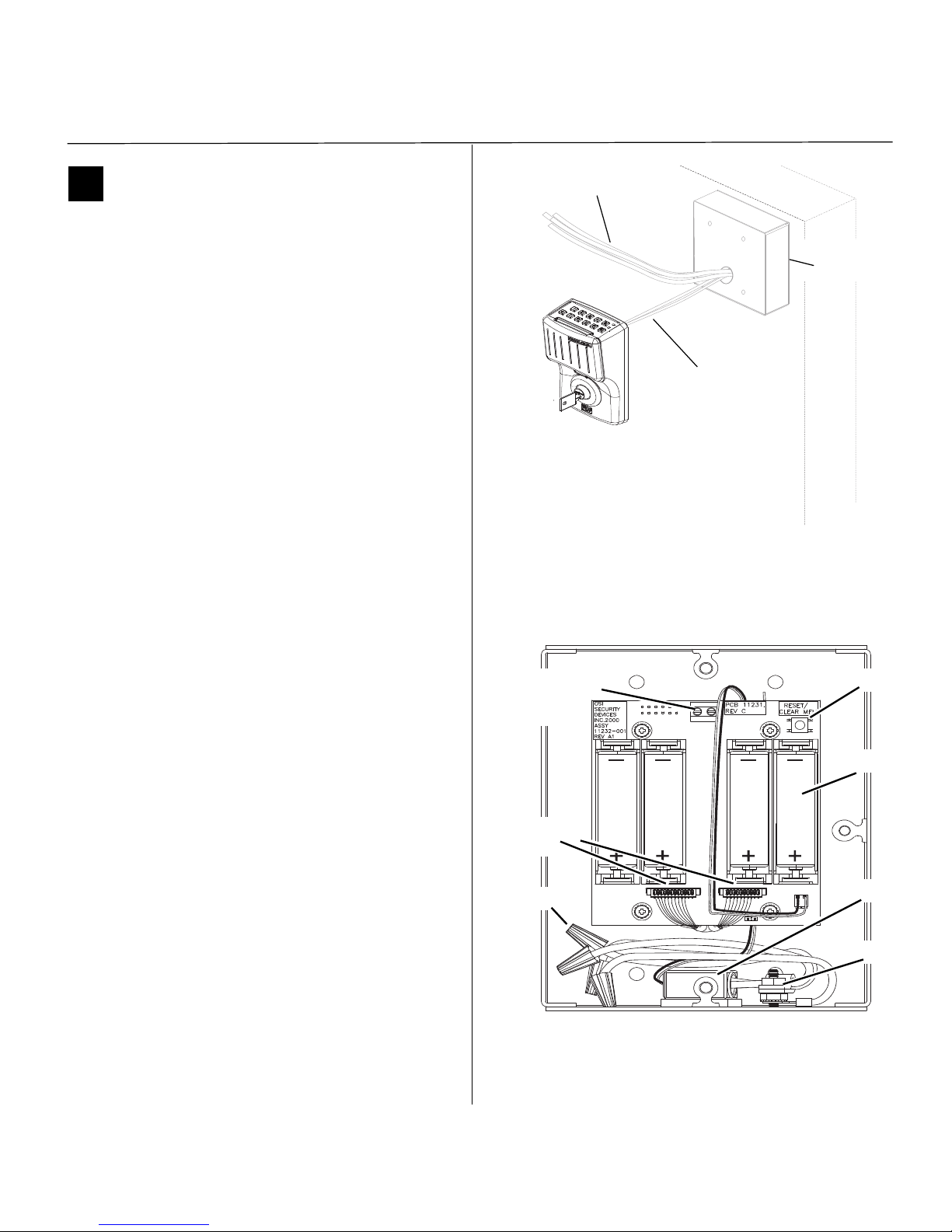
If the mechanism doesn’t unlock, remove the battery
cover and check for proper orientation and seating
of the batteries and motor connector. Ensure that
wires are not pinched. Reset the electronics by press-
ing and holding the reset button on the circuit board
until the light flashes green (approximately three
seconds), then releasing the button. See Figure 3.
Note: The system will go through a self-test and the
green light will flash. You will hear the unit unlock,
then relock three times. A red flash indicates a
circuit board or drive system problem. If a red flash
or no flash is observed, check for proper orientation
and seating of the batteries and motor connector,
ensure that wires are not pinched, then repeat the
reset process.

This manual suits for next models

1

Other Stanley Lock manuals

Stanley OmniLock Instruction Manual

Stanley

Stanley OmniLock Instruction Manual

Stanley BEST 45HG User manual

Stanley

Stanley BEST 45HG User manual

Stanley 3 Series User manual

Stanley

Stanley 3 Series User manual

Stanley QCI 200 User manual

Stanley

Stanley QCI 200 User manual

Stanley GS3-MT PIN User manual

Stanley

Stanley GS3-MT PIN User manual

Stanley Omnilock 45HOM User manual

Stanley

Stanley Omnilock 45HOM User manual

Stanley QEL 200 User manual

Stanley

Stanley QEL 200 User manual

Stanley Sargent and Greenleaf 6730 User manual

Stanley

Stanley Sargent and Greenleaf 6730 User manual

Stanley Omnilock 9KOM User manual

Stanley

Stanley Omnilock 9KOM User manual

Stanley BEST ACCESS SYSTEMS 45HM Series User manual

Stanley

Stanley BEST ACCESS SYSTEMS 45HM Series User manual

Stanley 203820 User manual

Stanley

Stanley 203820 User manual

Stanley Omnilock 45HOM User manual

Stanley

Stanley Omnilock 45HOM User manual

Stanley QEL 200 User manual

Stanley

Stanley QEL 200 User manual

Stanley Omnilock QAXOM User manual

Stanley

Stanley Omnilock QAXOM User manual

Stanley QET320 User manual

Stanley

Stanley QET320 User manual

Stanley QEL 200 User manual

Stanley

Stanley QEL 200 User manual

Stanley 83KM-93KM User manual

Stanley

Stanley 83KM-93KM User manual

Stanley Shelter 9KX User manual

Stanley

Stanley Shelter 9KX User manual

Stanley 9K Series User manual

Stanley

Stanley 9K Series User manual

Popular Lock manuals by other brands

IKEA ROTHULT E1778 manual

IKEA

IKEA ROTHULT E1778 manual

Porter-Cable 513 instruction manual

Porter-Cable

Porter-Cable 513 instruction manual

Chatsworth Products Communications Module 16147-010 Product application

Chatsworth Products

Chatsworth Products Communications Module 16147-010 Product application

Sargent Profile Series installation instructions

Sargent

Sargent Profile Series installation instructions

GTO FM145 installation manual

GTO

GTO FM145 installation manual

Kwikset Henley 300HYL 15 installation guide

Kwikset

Kwikset Henley 300HYL 15 installation guide

Burg Wächter Scan & Lock 610/53 Operation instructions

Burg Wächter

Burg Wächter Scan & Lock 610/53 Operation instructions

Schlage L9000 Series installation instructions

Schlage

Schlage L9000 Series installation instructions

Salto Aelement installation guide

Salto

Salto Aelement installation guide

Assa Abloy Yale P113 Fitting instructions

Assa Abloy

Assa Abloy Yale P113 Fitting instructions

urmet domus 1086 quick start guide

urmet domus

urmet domus 1086 quick start guide

Hongda USA Shepherd 210A Operation manual

Hongda USA

Hongda USA Shepherd 210A Operation manual

ZKTeco AL20B user manual

ZKTeco

ZKTeco AL20B user manual

COMPX Chicago Tubar IC-12L instruction sheet

COMPX

COMPX Chicago Tubar IC-12L instruction sheet

CDVI V3E36R quick start guide

CDVI

CDVI V3E36R quick start guide

danalock V3 US Easy install

danalock

danalock V3 US Easy install

DESi DAK user manual

DESi

DESi DAK user manual

SilverCloud YR300 user manual

SilverCloud

SilverCloud YR300 user manual

manuals.online logo
manuals.online logoBrands
  • About & Mission
  • Contact us
  • Privacy Policy
  • Terms and Conditions

Copyright 2025 Manuals.Online. All Rights Reserved.