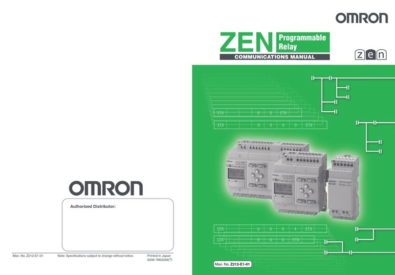
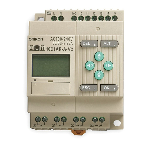
Omron ZEN User manual

ZEN
C
at.No. W
385
-E1-
04

ZEN Programmable Relay
Operation Manual
Produced April 2003

iv

v
Notice:
OMRON products are manufactured for use according to proper procedures by a
qualified operator and only for the purposes described in this manual.
The following conventions are used to indicate and classify precautions in this man-
ual. Always heed the information provided with them. Failure to heed precautions
can result in injury to people or damage to property.
!DANGER Indicates an imminently hazardous situation which, if not avoided, will
result in death or serious injury.
!WARNING Indicates a potentially hazardous situation which, if not avoided, could
result in death or serious injury.
!Caution Indicates a potentially hazardous situation which, if not avoided, may
result in minor or moderate injury, or property damage.

vi
OMRON Product References
All OMRON products are capitalized in this manual. The word “Unit” is also capital-
ized when it refers to an OMRON product, regardless of whether or not it appears in
the proper name of the product.
Visual Aids
The following headings appear in the left column of the manual to help you locate dif-
ferent types of information.
Note Indicates information of particular interest for efficient and convenient
operation of the product.
1,2,3... 1. Indicates lists of one sort or another, such as procedures, check-
lists, etc.
Precaution Indicates precautionary information that should be heeded in using
the ZEN.
Indicate the buttons that needs to be pressed in operating proce-
dures. Press each button once.
Indicate buttons that needs to be pressed in operating procedures.
Press one of the buttons once or more.
▲▼
Indicates that the display (the word “LANGUAGE” in this case) is
flashing. In this manual, this state is described by saying that the
“flashing cursor” is at the word “LANGUAGE”. In this state it is possi-
ble to change settings and the position of the cursor.
/$1*8$*(
Indicates that the display (the letter “H” in this case) is flashing in
reverse video. In this manual, this state is described by saying that
the “highlighted cursor” is at the word “H”. In this state it is not possi-
ble to change settings but the cursor can be changed to the flashing
cursor by pressing the OK button.
581
3$5$0(7(5
6(7&/2&.
/$1*8$*(
(1*/,6+
OMRON, 2001
All rights reserved. No part of this publication may be reproduced, stored in a retrieval sys-
tem, or transmitted, in any form, or by any means, mechanical, electronic, photocopying,
recording, or otherwise, without the prior written permission of OMRON.
No patent liability is assumed with respect to the use of the information contained herein.
Moreover, because OMRON is constantly striving to improve its high-quality products, the
information contained in this manual is subject to change without notice. Every precaution
has been taken in the preparation of this manual. Nevertheless, OMRON assumes no
responsibility for errors or omissions. Neither is any liability assumed for damages resulting
from the use of the information contained in this publication.
vii
TABLE OF CONTENTS
PRECAUTIONS. . . . . . . . . . . . . . . . . . . . . . . . . . . . . . . . . . . . . . . .xi
1 Safety Precautions . . . . . . . . . . . . . . . . . . . . . . . . . . . . . . . . . . . . . . . . . . . . . xii
2 Application Precautions. . . . . . . . . . . . . . . . . . . . . . . . . . . . . . . . . . . . . . . . . xiii
3 Operating Environment Precautions . . . . . . . . . . . . . . . . . . . . . . . . . . . . . . . xvi
4 Conformance to EC Directives . . . . . . . . . . . . . . . . . . . . . . . . . . . . . . . . . . . xvi
5 Operating Mode at Startup. . . . . . . . . . . . . . . . . . . . . . . . . . . . . . . . . . . . . . . xix
6 Memory Backup. . . . . . . . . . . . . . . . . . . . . . . . . . . . . . . . . . . . . . . . . . . . . . . xx
7 Version Upgrades. . . . . . . . . . . . . . . . . . . . . . . . . . . . . . . . . . . . . . . . . . . . . . xxi
SECTION 1
Outline . . . . . . . . . . . . . . . . . . . . . . . . . . . . . . . . . . . . . . . . . . . . . . . .1
1-1 Outline . . . . . . . . . . . . . . . . . . . . . . . . . . . . . . . . . . . . . . . . . . . . . . . . . . . . . . 2
1-2 Features and Part Names . . . . . . . . . . . . . . . . . . . . . . . . . . . . . . . . . . . . . . . . 8
1-3 Display Screen and Basic Operations . . . . . . . . . . . . . . . . . . . . . . . . . . . . . . 16
1-4 Memory Areas . . . . . . . . . . . . . . . . . . . . . . . . . . . . . . . . . . . . . . . . . . . . . . . . 27
1-5 Allocating I/O Bit Numbers. . . . . . . . . . . . . . . . . . . . . . . . . . . . . . . . . . . . . . 29
1-6 Preparations for Operation. . . . . . . . . . . . . . . . . . . . . . . . . . . . . . . . . . . . . . . 30
SECTION 2
Installation and Wiring . . . . . . . . . . . . . . . . . . . . . . . . . . . . . . . . . .31
2-1 Mounting . . . . . . . . . . . . . . . . . . . . . . . . . . . . . . . . . . . . . . . . . . . . . . . . . . . . 32
2-2 Wiring . . . . . . . . . . . . . . . . . . . . . . . . . . . . . . . . . . . . . . . . . . . . . . . . . . . . . . 33
SECTION 3
Programming and Operating Methods . . . . . . . . . . . . . . . . . . . . .49
3-1 Selecting Display Language . . . . . . . . . . . . . . . . . . . . . . . . . . . . . . . . . . . . . 50
3-2 Setting the Date and Time . . . . . . . . . . . . . . . . . . . . . . . . . . . . . . . . . . . . . . . 51
3-3 Creating Ladder Programs. . . . . . . . . . . . . . . . . . . . . . . . . . . . . . . . . . . . . . . 52
3-4 Confirming Ladder Program Operation. . . . . . . . . . . . . . . . . . . . . . . . . . . . . 62
3-5 Correcting Ladder Programs . . . . . . . . . . . . . . . . . . . . . . . . . . . . . . . . . . . . . 64
3-6 Using Timers (T) and Holding Timers (#). . . . . . . . . . . . . . . . . . . . . . . . . . . 67
3-7 Using Counters (C) . . . . . . . . . . . . . . . . . . . . . . . . . . . . . . . . . . . . . . . . . . . . 70
3-8 Using Weekly Timers (@) . . . . . . . . . . . . . . . . . . . . . . . . . . . . . . . . . . . . . . . 72
3-9 Using Calendar Timers (*). . . . . . . . . . . . . . . . . . . . . . . . . . . . . . . . . . . . . . . 74
3-10 Analog Inputs (Analog Comparators (A)). . . . . . . . . . . . . . . . . . . . . . . . . . . 75
3-11 Comparing Timer/Counter Present Values Using Comparators (P) . . . . . . . 79
3-12 Displaying Messages (Display Bits (D)) . . . . . . . . . . . . . . . . . . . . . . . . . . . . 82
3-13 Using Button Switches (B) . . . . . . . . . . . . . . . . . . . . . . . . . . . . . . . . . . . . . . 85

viii
TABLE OF CONTENTS
SECTION 4
Special Functions. . . . . . . . . . . . . . . . . . . . . . . . . . . . . . . . . . . . . . . 87
4-1 Protecting Programs. . . . . . . . . . . . . . . . . . . . . . . . . . . . . . . . . . . . . . . . . . . . 88
4-2 Stabilizing Input Operations. . . . . . . . . . . . . . . . . . . . . . . . . . . . . . . . . . . . . . 90
4-3 Changing Backlight Automatic Cutout Time. . . . . . . . . . . . . . . . . . . . . . . . . 92
4-4 Adjusting LCD Screen Contrast. . . . . . . . . . . . . . . . . . . . . . . . . . . . . . . . . . . 93
4-5 Setting Summertime. . . . . . . . . . . . . . . . . . . . . . . . . . . . . . . . . . . . . . . . . . . . 93
4-6 Reading System Information . . . . . . . . . . . . . . . . . . . . . . . . . . . . . . . . . . . . . 94
SECTION 5
Optional Products . . . . . . . . . . . . . . . . . . . . . . . . . . . . . . . . . . . . . . 95
5-1 Mounting Battery Units . . . . . . . . . . . . . . . . . . . . . . . . . . . . . . . . . . . . . . . . . 96
5-2 Using Memory Cassettes . . . . . . . . . . . . . . . . . . . . . . . . . . . . . . . . . . . . . . . . 97
5-3 Connecting the ZEN Support Software . . . . . . . . . . . . . . . . . . . . . . . . . . . . . 99
SECTION 6
Troubleshooting. . . . . . . . . . . . . . . . . . . . . . . . . . . . . . . . . . . . . . . . 101
6-1 Troubleshooting . . . . . . . . . . . . . . . . . . . . . . . . . . . . . . . . . . . . . . . . . . . . . . . 102
6-2 Error Messages. . . . . . . . . . . . . . . . . . . . . . . . . . . . . . . . . . . . . . . . . . . . . . . . 102
6-3 Deleting Error Messages . . . . . . . . . . . . . . . . . . . . . . . . . . . . . . . . . . . . . . . . 104
Appendices
A Product Configurations . . . . . . . . . . . . . . . . . . . . . . . . . . . . . . . . . . . . . . . . . 105
B Specifications . . . . . . . . . . . . . . . . . . . . . . . . . . . . . . . . . . . . . . . . . . . . . . . . 109
C Ladder Program Execution . . . . . . . . . . . . . . . . . . . . . . . . . . . . . . . . . . . . . . 121
D Application Examples . . . . . . . . . . . . . . . . . . . . . . . . . . . . . . . . . . . . . . . . . . 123
E Allocations and Setting Sheets . . . . . . . . . . . . . . . . . . . . . . . . . . . . . . . . . . . 137
Index . . . . . . . . . . . . . . . . . . . . . . . . . . . . . . . . . . . . . . . . . . . . . . . . . 145
Revision History . . . . . . . . . . . . . . . . . . . . . . . . . . . . . . . . . . . . . . . 149

ix
About this Manual:
This manual describes the installation and operation of the ZEN Programmable
Relay and includes the sections described below.
Please read this manual carefully and be sure you understand the information
provided before attempting to install or operate the ZEN. Be sure to read the
precautions provided in the following section.
Precautions provides general precautions for using the ZEN and related
devices.
Section 1 gives an outline of the ZEN, including example applications, the sys-
tem configurations and basic operations.
Section 2 explains how to mount and wire the ZEN CPU Units and Expansion
I/O Units.
Section 3 explains how to create and edit ladder programs and how to use the
timers, counters, comparators, display function and buttons switches.
Section 4 describes how to protect ladder programs, stabilize inputs, make
LCD screen adjustments, and make summer time settings.
Section 5 describes how to mount Battery Units, use Memory Cassettes, and
how to connect the ZEN Support Software.
Section 6 lists the error messages and provides probable causes and counter-
measures for troubleshooting.
The following two manuals are provided for the ZEN Programmable Relay.
Refer to them as required in operation.
Manual Contents Cat. No.
ZEN Programmable Relay
Operation Manual ZEN specifications, functions, and operat-
ing methods. W385
ZEN Support Software
Operation Manual Installation and operating procedures for
the ZEN Support Software W386
!WARNING Failure to read and understand the information provided in this manual may
result in personal injury or death, damage to the product, or product failure.
Please read each section in its entirety and be sure you understand the infor-
mation provided in the section and related sections before attempting any of
the procedures or operations given.


xi
PRECAUTIONS
This section provides general precautions for using the ZEN Programmable Relay.
The information contained in this section is important for the safe and reliable application
of the ZEN. You must read this section and understand the information contained before
attempting to set up or operate the ZEN.
1 Safety Precautions . . . . . . . . . . . . . . . . . . . . . . . . . . . . . . . . . . . . . . . . . . . . . xii
2 Application Precautions. . . . . . . . . . . . . . . . . . . . . . . . . . . . . . . . . . . . . . . . . xiii
2-1 Circuit Design and Ladder Programming . . . . . . . . . . . . . . . . . . . xiii
2-2 Installation . . . . . . . . . . . . . . . . . . . . . . . . . . . . . . . . . . . . . . . . . . . xiii
2-3 Wiring and Connections. . . . . . . . . . . . . . . . . . . . . . . . . . . . . . . . . xiii
2-4 I/O Connections and Startup Precautions . . . . . . . . . . . . . . . . . . . xiv
2-5 Handling. . . . . . . . . . . . . . . . . . . . . . . . . . . . . . . . . . . . . . . . . . . . . xiv
2-6 Maintenance. . . . . . . . . . . . . . . . . . . . . . . . . . . . . . . . . . . . . . . . . . xv
2-7 Transportation and Storage . . . . . . . . . . . . . . . . . . . . . . . . . . . . . . xv
3 Operating Environment Precautions . . . . . . . . . . . . . . . . . . . . . . . . . . . . . . . xvi
4 Conformance to EC Directives . . . . . . . . . . . . . . . . . . . . . . . . . . . . . . . . . . . xvi
4-1 Applicable Directives. . . . . . . . . . . . . . . . . . . . . . . . . . . . . . . . . . . xvi
4-2 Concepts. . . . . . . . . . . . . . . . . . . . . . . . . . . . . . . . . . . . . . . . . . . . . xvi
4-3 Conformance to EC Directives . . . . . . . . . . . . . . . . . . . . . . . . . . . xvii
4-4 Relay Output Noise Reduction Methods . . . . . . . . . . . . . . . . . . . . xvii
5 Operating Mode at Startup. . . . . . . . . . . . . . . . . . . . . . . . . . . . . . . . . . . . . . . xix
6 Memory Backup. . . . . . . . . . . . . . . . . . . . . . . . . . . . . . . . . . . . . . . . . . . . . . . xx
7 Version Upgrades. . . . . . . . . . . . . . . . . . . . . . . . . . . . . . . . . . . . . . . . . . . . . . xxi
7-1 Application Precautions for Differences between Versions. . . . . . xxii
7-2 CPU Units Covered in this Manual . . . . . . . . . . . . . . . . . . . . . . . . xxiii

xii
Safety Precautions 1
1 Safety Precautions
!WARNING Never attempt to disassemble any Units while power is being
supplied. Doing so may result in serious electrical shock or elec-
trocution.
!WARNING Never touch the I/O terminals, computer connector, Expansion
Unit connector, or Battery Unit connector while power is being
supplied. Doing so may result in serious electrical shock or elec-
trocution.
!WARNING Provide safety measures in external circuits (i.e., not in the ZEN),
including the following items, to ensure safety in the system if an
abnormality occurs due to malfunction of the ZEN or another
external factor affecting the ZEN operation. Not doing so may
result in serious accidents.
• Emergency stop circuits, interlock circuits, limit circuits, and simi-
lar safety measures must be provided in external control circuits.
• The ZEN will turn OFF all outputs when its self-diagnosis func-
tion detects any error. As a countermeasure for such errors,
external safety measures must be provided to ensure safety in
the system.
• The ZEN outputs may remain ON or OFF due to deposition or
burning of the output relays or destruction of the output transis-
tors. As a countermeasure for such problems, external safety
measures must be provided to ensure safety in the system.
• Provide double safety mechanisms to handle incorrect signals
that can be generated by broken signal lines or momentary
power interruptions.
!WARNING Do not short the battery terminals or charge, disassemble, heat,
or incinerate the battery. Do not subject the battery to strong
shocks. Doing any of these may result in leakage, rupture, heat
generation, or ignition of the battery. Dispose of any battery that
has been dropped on the floor or otherwise subjected to exces-
sive shock. Batteries that have been subjected to shock may leak
if they are used.
!Caution Tighten the AC power supply terminal block screws to the torque
specified in the manual. Loose screws can result in fire or faulty
operation.

xiii
Application Precautions 2
2 Application Precautions
Observe the following precautions when using the ZEN.
2-1 Circuit Design and Ladder Programming
• Provide external interlock circuits, limit circuits, and other safety
circuits in addition to any provided within the ZEN to ensure
safety.
• The output relays or the output transistors may remain ON due to
faults in internal circuits such as output relays or output transis-
tors. As a countermeasure for such problems, external safety
measures must be provided to ensure safety in the system.
• Always turn ON power to the ZEN before turning ON power to
the I/O circuits. If the ZEN power supply is turned ON after the I/
O power supply, temporary errors may result in operation.
• The life of the output relays is largely affected by the switching
conditions. Confirm the operation of the system under actual
operating conditions and set the switching frequency to ensure
that adequate performance will be provided. Insulation faults and
burning in the ZEN may result if relays are used after their perfor-
mance has deteriorated.
2-2 Installation
• Install the ZEN according to instructions in the operation manual.
Improper installation may cause faulty operation.
• Do not install the ZEN in locations subject to excessive noise.
Malfunction may occur.
• Do not allow the ZEN to fall during installation.
• Be sure that all the mounting screws on the ZEN and Expansion
I/O Unit are tightened to the torque specified in the manual.
Incorrect tightening torque may result in malfunction.
• Use with the cover of the computer connector mounted. Using
without the cover may result in malfunction due to dust or other
foreign matter.
• Be sure that the DIN rail mounting levers, Expansion I/O Units,
Memory Cassettes, Battery Units, cable connectors, and other
items with locking devices are properly locked into place.
Improper locking may result in malfunction.
2-3 Wiring and Connections
• Use the wires specified in this manual when wiring. Use straight
crimp terminals when connecting loose wires.

xiv
Application Precautions 2
• Provide circuit breakers and other safety measures to provide
protection against shorts in external wiring.
• Use separate wiring ducts for signal wires from those used for
power supply and high-voltage lines.
• Always check polarity when connecting cables.
• Leave the label attached to the Unit when wiring. Removing the
label may result in malfunction if foreign matter enters the Unit.
• Remove the label after the completion of wiring to ensure proper
heat dissipation. Leaving the label attached may result in mal-
function.
• Tighten the terminal block screws to the torque specified in the
manual.
• Wire the ZEN according to instructions in the operation manual.
Improper installation may cause faulty operation.
2-4 I/O Connections and Startup Precautions
• Use the Units only with the power supplies and voltages speci-
fied in the operation manual. Other power supplies and voltages
may damage the Units.
• Take measures to stabilize the power supply to conform to the
rated supply if it is not stable.
• Do not apply voltages exceeding the rated input voltage to input
circuits. The input circuits may be destroyed.
• Do not apply voltages exceeding the maximum switching capac-
ity to output circuits. The output circuits may be destroyed.
• Double-check all wiring before turning ON the power supply.
Incorrect wiring may result in burning.
• Check the user program for proper execution before actually run-
ning it on the Unit. Not checking the program may result in an
unexpected operation.
2-5 Handling
• Use, store, and transport the ZEN under the limits given for gen-
eral specifications in this manual.
• Do not attempt to disassemble, repair, or modify any Units. Any
attempt to do so may result in malfunction, fire, or electric shock.
• Always turn OFF the power supply to the ZEN before attempting
any of the following.
• Assembling the ZEN.
• Attaching or removing the Expansion I/O Unit.
• Connecting or disconnecting any cables or wiring.

xv
Application Precautions 2
• Attaching or removing the Memory Cassette.
• Attaching or removing the Battery Unit.
• Confirm that no adverse effect will occur in the system before
attempting any of the following. Not doing so may result in an
unexpected operation.
• Changing the operating mode.
• Using the button switches.
• Changing bit status or parameter settings.
• Before touching a Unit, be sure to first touch a grounded metallic
object in order to discharge any static build-up.
• Do not pull on the cables or bend the cables beyond their natural
limit. Doing either of these may break the cables.
• Do not place objects on top of the cables or other wiring lines.
Doing so may break the cables.
• Do not short the battery terminals or charge, disassemble, heat,
or incinerate the battery. Do not subject the battery to strong
shocks. Doing any of these may result in leakage, rupture, heat
generation, or ignition of the battery. Dispose of any battery that
has been dropped on the floor or otherwise subjected to exces-
sive shock. Batteries that have been subjected to shock may
leak if they are used.
• Abide by all local ordinances and regulations when disposing of
the ZEN.
2-6 Maintenance
• When replacing parts, be sure to confirm that the rating of a new
part is correct.
• When replacing a Unit, transfer to the new Unit and confirm all
settings for clock data, internal holding bits, holding timers, and
counter before starting operation again.
2-7 Transportation and Storage
• Use special packaging boxes when transporting the ZEN and do
not subject it to excessive shock or vibration or drop it during
shipment.
• Store the ZEN in the following temperature and humidity ranges
without condensation or icing.
Model Ambient
temperature Humidity
LCD –20 to 75°C 10% to 90%
LED –40 to 75°C

xvi
Operating Environment Precautions 3
3 Operating Environment Precautions
Do not operate the control system in the following places.
• Where the ZEN is exposed to direct sunlight.
• Where the ambient temperature or humidity is beyond the speci-
fied ranges.
• Where the ZEN may be affected by condensation due to radical
temperature changes.
• Where there is any corrosive or inflammable gas.
• Where there is excessive dust, saline air, or metal powder.
• Where the ZEN is affected by vibration or shock.
• Where any water, oil or chemical may splash on the ZEN.
• Any other place with conditions beyond those specified in the
general specifications.
Take appropriate and sufficient countermeasures when installing sys-
tems in the following locations:
• Locations subject to static electricity or other forms of noise.
• Locations subject to strong electromagnetic fields.
• Locations subject to possible exposure to radioactivity.
• Locations close to power supplies.
4 Conformance to EC Directives
4-1 Applicable Directives
•EMCDirectives
• Low Voltage Directive
4-2 Concepts
EMC Directives
OMRON devices that comply with EC Directives also conform
to the related EMC standards so that they can be more easily
built into other devices or the overall machine. The actual
products have been checked for conformity to EMC standards
(see the following note). Whether the products conform to the
standards in the system used by the customer, however, must
be checked by the customer.
EMC-related performance of the OMRON devices that comply
with EC Directives will vary depending on the configuration,

xvii
Conformance to EC Directives 4
wiring, and other conditions of the equipment or control panel
on which the OMRON devices are installed. The customer
must, therefore, perform the final check to confirm that devices
and the overall machine conform to EMC standards.
Note Applicable EMC (Electromagnetic Compatibility) standards are as
follows:
EMS (Electromagnetic Susceptibility): EN61000-6-2
EMI (Electromagnetic Interference): EN50081-2
(Radiated emission: 10-m regulations)
Low Voltage Directive
Always ensure that devices operating at voltages of 50 to
1,000 VAC and 75 to 1,500 VDC meet the required safety
standards for the ZEN (EN61131-2).
4-3 Conformance to EC Directives
The ZEN complies with EC Directives. To ensure that the machine or
device in which the ZEN is used complies with EC Directives, the
ZEN must be installed as follows:
1,2,3... 1. The ZEN must be installed within a control panel.
2. You must use reinforced insulation or double insulation for the DC
power supplies used for the communications power supply and I/
O power supplies.
3. ZEN models complying with EC Directives also conform to the
Common Emission Standard (EN50081-2). Radiated emission
characteristics (10-m regulations) may vary depending on the
configuration of the control panel used, other devices connected
to the control panel, wiring, and other conditions.
You must therefore confirm that the overall machine or equipment
complies with EC Directives.
4-4 Relay Output Noise Reduction Methods
The ZEN conforms to the Common Emission Standards (EN50081-2)
of the EMC Directives. However, noise generated by relay output
switching may not satisfy these Standards. In such a case, a noise fil-
ter must be connected to the load side or other appropriate counter-
measures must be provided external to the ZEN.
Countermeasures taken to satisfy the standards vary depending on
the devices on the load side, wiring, configuration of machines, etc.
Following are examples of countermeasures for reducing the gener-
ated noise.

xviii
Conformance to EC Directives 4
Countermeasures
(Refer to EN50081-2 for more details.)
Countermeasures are not required if the frequency of load switching
for the whole system with the ZEN included is less than 5 times per
minute.
Countermeasures are required if the frequency of load switching for
the whole system with the ZEN included is more than 5 times per
minute.
Countermeasure Examples
When switching an inductive load, connect an surge protector,
diodes, etc., in parallel with the load or contact as shown below.
Circuit Current Characteristic Required element
AC DC
CR method Yes Yes If the load is a relay or
solenoid, there is a time
lag between the moment
the circuit is opened and
the moment the load is
reset.
If the supply voltage is 24
or 48 V, insert the surge
protector in parallel with
the load. If the supply volt-
age is 100 to 200 V, insert
the surge protector
between the contacts.
The capacitance of the capaci-
tor must be 1 to 0.5 µF per
contact current of 1 A and
resistance of the resistor must
be 0.5 to 1 Ωper contact volt-
age of 1 V. These values, how-
ever, vary with the load and
the characteristics of the relay.
Decide these values from
experiments, and take into
consideration that the capaci-
tance suppresses spark dis-
charge when the contacts are
separated and the resistance
limits the current that flows
into the load when the circuit is
closed again.
The dielectric strength of the
capacitor must be 200 to 300
V. If the circuit is an AC circuit,
use a capacitor with no polar-
ity.
Power
supply
Inductive
load

xix
Operating Mode at Startup 5
5 Operating Mode at Startup
The operating mode at startup depends on the model and the pres-
ence of a user program as shown in the following table.
Diode method No Yes The diode connected in
parallel with the load
changes energy accumu-
lated by the coil into a cur-
rent, which then flows into
the coil so that the current
will be converted into
Joule heat by the resis-
tance of the inductive
load.
This time lag, between
the moment the circuit is
opened and the moment
the load is reset, caused
by this method is longer
than that caused by the
CR method.
The reversed dielectric
strength value of the diode
must be at least 10 times as
large as the circuit voltage
value. The forward current of
the diode must be the same as
or larger than the load current.
The reversed dielectric
strength value of the diode
may be two to three times
larger than the supply voltage
if the surge protector is
applied to electronic circuits
with low circuit voltages.
Varistor method Yes Yes The varistor method pre-
vents the imposition of
high voltage between the
contacts by using the con-
stant voltage characteris-
tic of the varistor. There is
time lag between the
moment the circuit is
opened and the moment
the load is reset.
If the supply voltage is 24
or 48 V, insert the varistor
in parallel with the load. If
the supply voltage is 100
to 200 V, insert the varis-
tor between the contacts.
---
Circuit Current Characteristic Required element
AC DC
Power
supply
Inductive
load
Power
supply
Inductive
load
User
program In CPU No Yes No Yes
In Memory
Cassette No No Yes Yes
LCD model (with LCD and
operation buttons) STOP
mode RUN mode with
program in CPU RUN mode with program
in Memory Cassette RUN mode with
program in CPU
LED model (with LED and
no operation buttons) STOP
mode RUN mode with
program in CPU RUN mode with program
in Memory Cassette RUN mode with
program in CPU

xx
Memory Backup 6
6 Memory Backup
The ladder program and settings are stored in EEPROM and thus will
not be lost even if the power supply is turned OFF for an extended
period of time (e.g., 2 days at 25°C). The status of the following data,
however, is backed up by an internal capacitor, and may be lost if
power is turned OFF for an extended period of time: ON/OFF status
of holding bits (H), holding timers (#), and counters (C) and the pre-
vent value areas. For models equipped with a clock/calendar, the
time and date may be reset. Always reconfirm system operation
before restarting operation after the power has been turned OFF for
an extended period of time. We recommend that a Battery Unit be
(optional) connected in any system in which power may be inter-
rupted for an extended period of time.

xxi
Version Upgrades 7
7 Version Upgrades
The following table shows the relationship between the versions and
functionality of the ZEN CPU Unit and ZEN Support Software
Note 1. Thenumber of the system software version in the CPU Unit is not
related to the model number. The system software version of
CPU Units with LCDs can be read by selecting SYSTEM INFO
from the OTHER Menu. “V02.00” will be displayed as the system
software version for V1 CPU Units.
Date of
upgrade CPU Unit Support Software
System
software
version
Main changes
January
2002 Ver. 1.10 The following functions were added to the CPU
Units with LCD displays.
• A Clear Display function
• A Day/Month display object (DAT1)
The following functions
were added to version
2.00 (ZEN-SOFT01-V2).
• Support for changes to
display function
• Simulation function
• Improvements to func-
tions, operating proce-
dures, and displays
May
2003 Ver. 2.00 • The number of timers, counters, weekly tim-
ers, calendar timers, and display areas was
increased from 8 to 16 each and the number
of holding timers was increased from 4 to 8.
(See note 2.)
• A new CPU Unit with 20 I/O points was
added. (See note 2.)
• The input circuits of CPU Units with DC
power supply were made compatible with
both PNP and NPN.
• A password input was added to the memory
all clear function for CPU Units with LCDs.
Note The model numbers of CPU Units with
10 or 20 I/O points end in “-V1.”
The following functions
were added to version
3.00 (ZEN-SOFT01-V3).
• Support for V1 CPU
Units with 20 I/O points
• Support for V1 CPU
Units with 10 I/O points
Other manuals for ZEN
3
Table of contents
Other Omron Relay manuals

Omron
Omron G9SB - DATASHEET 1 User manual

Omron
Omron K8DT-VS Series User manual

Omron
Omron K8DT-AW Series User manual

Omron
Omron ZEN-8E Use and care manual

Omron
Omron G7SA User manual

Omron
Omron K8AK-AS User manual

Omron
Omron G2RV - 1 User manual

Omron
Omron G3PA-450B-VD-2 User manual

Omron
Omron G3PA User manual

Omron
Omron G3PE Series User manual

Omron
Omron MK-S - 2 User manual

Omron
Omron SYSMAC W398-E1-1 User manual

Omron
Omron G3PJ Series User manual

Omron
Omron K8AB-AS User manual

Omron
Omron G3PA-VD Series User manual

Omron
Omron LY - User manual

Omron
Omron SR203M User manual

Omron
Omron K8DT-TH User manual

Omron
Omron G2RV - 1 User manual

Omron
Omron J7KNA-AR User manual