manuals.online logo
Brands
  1. Home
  2. •
  3. Brands
  4. •
  5. Omron
  6. •
  7. Relay
  8. •
  9. Omron MYK User manual

Omron MYK User manual

Other Omron Relay manuals

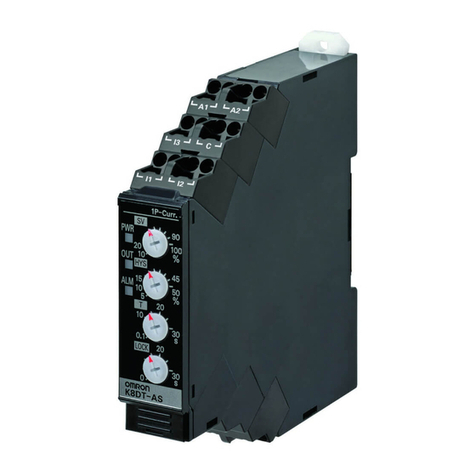
Omron K8DT-AS Seriesl User manual

Omron

Omron K8DT-AS Seriesl User manual

Omron K8AK-VW3 User manual

Omron

Omron K8AK-VW3 User manual

Omron G3PE Series User manual

Omron

Omron G3PE Series User manual

Omron K8AB-AS User manual

Omron

Omron K8AB-AS User manual

Omron G9SE-201 User manual

Omron

Omron G9SE-201 User manual

Omron SR104P Operation manual

Omron

Omron SR104P Operation manual

Omron SR203M User manual

Omron

Omron SR203M User manual

Omron K6EL User manual

Omron

Omron K6EL User manual

Omron G2RV -  1 User manual

Omron

Omron G2RV - 1 User manual

Omron K8AB-VW Series User manual

Omron

Omron K8AB-VW Series User manual

Omron G9SX-ADA222-T Series User manual

Omron

Omron G9SX-ADA222-T Series User manual

Omron K8AK-VS User manual

Omron

Omron K8AK-VS User manual

Omron K8DT-AS Series User manual

Omron

Omron K8DT-AS Series User manual

Omron MY4H User manual

Omron

Omron MY4H User manual

Omron K8DT-PZ Series User manual

Omron

Omron K8DT-PZ Series User manual

Omron K8AB-VW Series User manual

Omron

Omron K8AB-VW Series User manual

Omron Sti SR120MP User manual

Omron

Omron Sti SR120MP User manual

Omron K8AB-TH User manual

Omron

Omron K8AB-TH User manual

Omron K8AB-PM Series User manual

Omron

Omron K8AB-PM Series User manual

Omron K8AK-VW2 24 VAC/DC User manual

Omron

Omron K8AK-VW2 24 VAC/DC User manual

Omron K8DT-VW User manual

Omron

Omron K8DT-VW User manual

Omron G9SA - User manual

Omron

Omron G9SA - User manual

Omron G3PA-VD Series User manual

Omron

Omron G3PA-VD Series User manual

Omron K8AK-PH1 200/500VAC User manual

Omron

Omron K8AK-PH1 200/500VAC User manual

Popular Relay manuals by other brands

Woodward BU1-DC2 manual

Woodward

Woodward BU1-DC2 manual

ABB SSR32 product manual

ABB

ABB SSR32 product manual

Siemens SIRIUS 3UG4633 operating instructions

Siemens

Siemens SIRIUS 3UG4633 operating instructions

Siemens SIRIUS 3TK2824 A.20 Series Original operating instructions

Siemens

Siemens SIRIUS 3TK2824 A.20 Series Original operating instructions

Shelly Pro Series user manual

Shelly

Shelly Pro Series user manual

GE MVAX 11 Technical manual

GE

GE MVAX 11 Technical manual

ABB RELION REF615R manual

ABB

ABB RELION REF615R manual

Kemo Electronic B197 quick guide

Kemo Electronic

Kemo Electronic B197 quick guide

Seg MRM3 manual

Seg

Seg MRM3 manual

Basler BE1-700C manual

Basler

Basler BE1-700C manual

CD Automation REVEX 2PH 280A user manual

CD Automation

CD Automation REVEX 2PH 280A user manual

ABB SPAJ 142 C User manual and technical description

ABB

ABB SPAJ 142 C User manual and technical description

Ruelco 1S04 Operation manual

Ruelco

Ruelco 1S04 Operation manual

Basler V3E Z1P B2C1F instruction manual

Basler

Basler V3E Z1P B2C1F instruction manual

GE DGP instruction manual

GE

GE DGP instruction manual

Kyongbo Electronics GDR-D01 user manual

Kyongbo Electronics

Kyongbo Electronics GDR-D01 user manual

Eaton easyE4 series Application note

Eaton

Eaton easyE4 series Application note

Siemens BD2-AK03X/FS Series installation instructions

Siemens

Siemens BD2-AK03X/FS Series installation instructions

manuals.online logo
manuals.online logoBrands
  • About & Mission
  • Contact us
  • Privacy Policy
  • Terms and Conditions

Copyright 2025 Manuals.Online. All Rights Reserved.

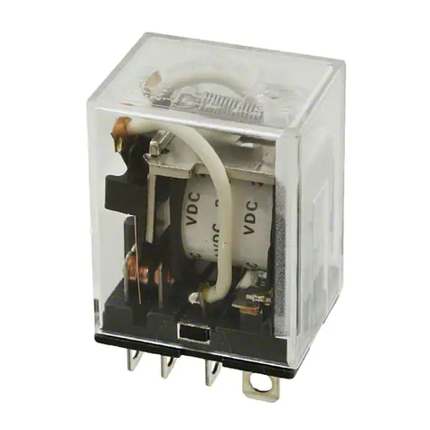
General-purpose Latching Relay MYK 1
General-purpose Latching Relay
MYK
Magnetic Latching Relay Ideal for Memory
and Data Transmission Circuits
• Double-winding latch system that holds residual magnetism.
• Changes due to aging are negligible because of use of special
magnetic materials, thus ensuring long continuous holding time.
• Little change in characteristics such as contact follow, contact
pressure, etc., throughout its long life.
• Excellent vibration/shock resistance.
• Easy monitoring of ON/OFF operation thanks to the built-in op-
eration indicator mechanism.
• Same outline dimensions as the MY Miniature Power Relay.
Ordering Information
■List of Models
■Accessories (Order Separately)
Connecting Sockets
Note: Refer to the MY Datasheet for detail information on the Relay Hold-down Clips and Relay-mounting Sockets.
Contact form Plug-in/solder
terminal model
PCB terminal
model
DPDT MY2K MY2K-02
Front-connecting Socket Back-connecting Socket
Screw terminals Solder terminals Wire-wrap terminals PCB terminals
Without Relay
Hold-down Clip
PYF14A-E
PYF14A
PYF14-N
PY14 PY14QN PY14-02
With Hold-down
Clip
--- PY14-Y1 PY14QN-Y1 ---
2General-purpose Latching Relay MYK
Specifications
■Coil Ratings
Note: 1. For AC models, the rated current values are half-wave rectified current values measured with a DC ammeter.
2. The rated current and coil resistance are measured at a coil temperature of 23°C with tolerances of +15%/–20% for AC rated current and
±15% for DC rated current, and +15% for DC coil resistance.
3. The AC coil resistance values are for reference only.
4. Performance characteristic data are measured at a coil temperature of 5°C to 35°C.
■Contact Ratings
*Note: P level: λ60 = 0.1 x 10⁻⁶/operation
■Characteristics
Note: The data shown above are initial values.
Rated voltage Set coil Reset coil Must-set
voltage
Must-
reset
voltage
Max.
voltage
Power
consumption
(Approx.)
Rated current Resistance Rated current Resistance % of rated voltage Set coil Reset
coil
50 Hz 60 Hz 50 Hz 60 Hz
AC 12 V 57 mA 56 mA 72 Ω39 mA 38.2 mA 130 Ω80%
max.
80%
max.
110% 0.6 to 0.9
(60 Hz)
0.2 to 0.5
(60 Hz)
24 V 27.5 mA 26.4 mA 320 Ω18.6 mA 18.1 mA 550 Ω
50 V 14.0 mA 13.4 mA 1,400 Ω3.5 mA 3.4 mA 3,000 Ω
100 V 7.1 mA 6.9 mA 5,400 Ω3.5 mA 3.4 mA 3,000 Ω
DC 12 V 110 mA 110 Ω50 mA 235 Ω1.3 W 0.6 W
24 V 52 mA 470 Ω25 mA 940 Ω
Item Resistive load (cosφ= 1) Inductive load (cosφ= 0.4) (L/R = 7 ms)
Rated load 3 A at 220 VAC, 3 A at 24 VDC 0.8 A at 220 VAC, 1.5 A at 24 VDC
Rated carry current 3 A
Max. switching voltage 250 VAC, 125 VDC
Max. switching current 3 A
Max. switching power 660 VA, 72 W 176 VA, 36 W
Failure rate* (reference value) 1 mA at 1 VDC
Contact resistance 50 mΩmax.
Set time Time: AC: 30 ms max.; DC: 15 ms max.
Min. pulse width: AC: 60 ms.; DC: 15 ms.
Reset time Time: AC: 30 ms max.; DC: 15 ms max.
Min. pulse width: AC: 60 ms.; DC: 15 ms.
Max. operating frequency Mechanical: 18,000 operations/hr
Electrical: 1,800 operations/hr (under rated load)
Insulation resistance 100 MΩmin. (at 500 VDC)
Dielectric strength 1,500 VAC, 50/60 Hz for 1 min (1,000 VAC between contacts of same polarity and between set and reset
coils)
Vibration resistance Destruction: 10 to 55 to 10 Hz, 0.5 mm single amplitude (1.0 mm double amplitude)
Malfunction: 10 to 55 to 10 Hz, 0.5 mm single amplitude (1.0 mm double amplitude)
Shock resistance Destruction: 1,000 m/s2
Malfunction: 200 m/s2
Endurance Mechanical: 100,000,000 operations min. (at 18,000 operations/hr)
Electrical: 200,000 operations min. (at 1,800 operations/hr)
Ambient temperature Operating: –55°C to 60°C (with no icing)
Ambient humidity Operating: 5% to 85%
Weight Approx. 30 g
General-purpose Latching Relay MYK 3
Engineering Data
Maximum Switched Power Endurance
Dimensions
10
500
1,000
5,000
10
500
1,000
5,000
Switchin
g
volta
g
e
(
V
)
Switching current (A)
AC resistive load
DC resistive load
Endurance (x103operations)
110 VAC resistive load
Switching current (A) Switchin
g
current
(
A
)
Endurance (x103operations)
110 VAC inductive load
(cosφ= 0.4)
30 VDC inductive load
(L/R = 7 ms)
220 VAC
inductive load
(cosφ= 0.4)
220 VAC
resistive load
30 VDC resistive
load
DC inductive load
(L/R = 7 ms)
AC
inductive
load
(cosφ=
0.4)
MY2K
MY2K-02
2.6
0.5
0.5
6.4
6.3
2.6
3.5
0.5
4
6.3
3.75
6.3
4.3
13.2
4.1
12.65
6.35
4.4
Mounting Holes
(Bottom View)
Note: Dimensional tolerances
are ±0.1 mm.
Ten, 1.2-dia. holes x 2.2 elliptic holes
36 max. 21.5 max.
28 max.
36 max. 21.5 max.
28 max.
Ten, 1.3-dia. holes
General-purpose Latching Relay MYK
R
Terminal Arrangement/Internal Connections (Bottom View)
Note: 1. Resistor is for ampere-turn compensation and is
incorporated in the Relay rated at 50 VAC or above.
2. Pay attention to the polarity of the set and reset coils,
as incorrect connection of positive and negative ter-
minal will result in the Relay malfunctioning.
AC Model DC Model
When using the Relay rated at 110 VAC at a supply volt-
age of 220 VAC, be sure to connect external resistors
Rs and Rr to the Relay.
If the supply voltage is applied to the set and reset coils
at the same time, the Relay will be put in the set state.
Use at 220 VAC
Rs: 7.3 kΩ3 W
Rr: 14.3 kΩ1 W
In the interest of product improvement, specifications are subject to change without notice.Cat. No. J013-E1-02
OMRON EUROPE B.V.
Wegalaan 67-69,
NL-2132 JD, Hoofddorp,
The Netherlands
Phone: +31 23 568 13 00
Fax: +31 23 568 13 88
www.eu.omron.com