Omron G9SA - User manual

-~
ARTISAN
®
~I
TECHNOLOGY
GROUP
Your definitive source
for
quality
pre-owned
equipment.
Artisan Technology
Group
Full-service,
independent
repair
center
with
experienced
engineers
and
technicians
on staff.
We
buy
your
excess,
underutilized,
and
idle
equipment
along
with
credit
for
buybacks
and
trade-ins
.
Custom
engineering
so
your
equipment
works
exactly as
you
specify.
•
Critical
and
expedited
services
•
Leasing
/
Rentals/
Demos
• In
stock/
Ready-to-ship
•
!TAR-certified
secure
asset
solutions
Expert
team
ITrust
guarantee
I
100%
satisfaction
All
tr
ademarks,
br
a
nd
names, a
nd
br
a
nd
s a
pp
earing here
in
are
th
e property of
th
e
ir
r
es
pecti
ve
ow
ner
s.
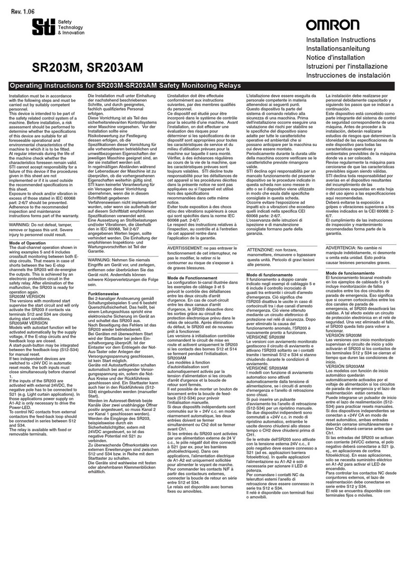
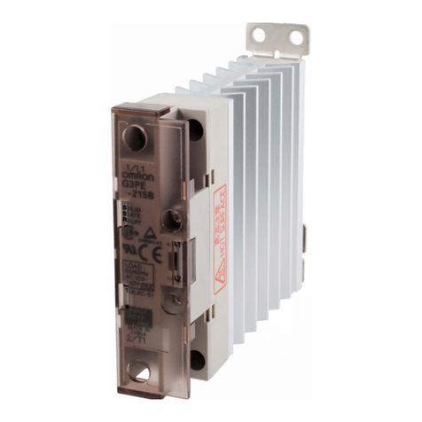
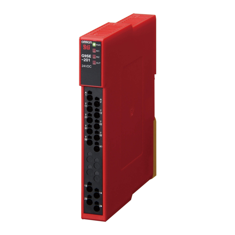
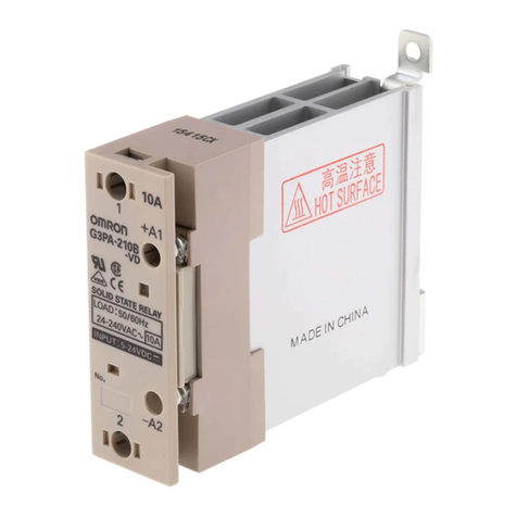
Find the OMRON G9SA-301 at our website: Click HERE

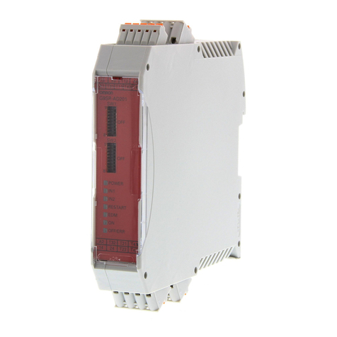
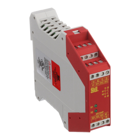
Safety Relay Unit
G9SA
The G9SA Series Offers a Complete Line-up
of Compact Units.
• Four kinds of 45-mm wide Units are available:
A 3-pole model, a 5-pole model, and models with 3 poles and 2
OFF-delay poles, as well as a Two-hand Controller.
Also available are 17.5-mm wide Expansion Units with 3 poles
and 3 OFF-delay poles.
• Simple expansion connection.
• OFF-delay models have 15-step OFF-delay settings.
• Conforms to EN standards. (BG approval)
• Certified by UL and CSA.
• Both DIN track mounting and screw mounting are possible.
Note: Be sure to read the “Safety Precautions” on page 13.
Ordering Information
Emergency-stop Units
Emergency-stop OFF-delay Units
Note: The following 15-step OFF-delay time settings are available:
T075: 0.5, 1, 1.5, 2, 2.5, 3, 3.5, 4, 4.5, 5, 5.5, 6, 6.5, 7, and 7.5 s
T15: 1, 2, 3, 4, 5, 6, 7, 8, 9, 10, 11, 12, 13, 14, and 15 s
T30: 2, 4, 6, 8, 10, 12, 14, 16, 18, 20, 22, 24, 26, 28, and 30 s
Two-hand Controller
Expansion Unit
The Expansion Unit connects to a G9SA-301, G9SA-501, G9SA-321, or G9SA-TH301.
Main contacts Auxiliary contact Number of input channels Rated voltage Model Category
3PST-NO SPST-NC 1 channel or 2 channels possible 24 VAC/VDC G9SA-301 4
100 to 240 VAC
5PST-NO 24 VAC/VDC G9SA-501
100 to 240 VAC
Main contacts OFF-delay
contacts
Auxiliary
contact
Number of
input channels
OFF-delay
time
Rated voltage Model Category
3PST-NO DPST-NO SPST-NC 1 channel or
2 channels
possible
7.5 s 24 VAC/VDC G9SA-321-T075 Main contacts:
4
OFF-delay
contacts:
3
100 to 240 VAC
15 s 24 VAC/VDC G9SA-321-T15
100 to 240 VAC
30 s 24 VAC/VDC G9SA-321-T30
100 to 240 VAC
Main contacts Auxiliary contact Number of input channels Rated voltage Model Category
3PST-NO SPST-NC 2 channels 24 VAC/VDC G9SA-TH301 4
100 to 240 VAC
Main contacts Auxiliary contact Model Category
3PST-NO SPST-NC G9SA-EX301 4
http://www.ia.omron.com/ 1
(c)Copyright OMRON Corporation 2007 All Rights Reserved.
Artisan Technology Group - Quality Instrumentation ... Guaranteed | (888) 88-SOURCE | www.artisantg.com
G9SA
Expansion Units with OFF-delay Outputs
The Expansion Unit connects to a G9SA-301, G9SA-501, G9SA-321, or G9SA-TH301.
Note: The following 15-step OFF-delay time settings are available:
T075: 0.5, 1, 1.5, 2, 2.5, 3, 3.5, 4, 4.5, 5, 5.5, 6, 6.5, 7, and 7.5 s
T15: 1, 2, 3, 4, 5, 6, 7, 8, 9, 10, 11, 12, 13, 14, and 15 s
T30: 2, 4, 6, 8, 10, 12, 14, 16, 18, 20, 22, 24, 26, 28, and 30 s
Model Number Structure
■Model Number Legend
1. Function
None: Emergency stop
EX: Expansion Unit
TH: Two-hand Controller
2. Contact Configuration (Safety Output)
0: None
3: 3PST-NO
5: 5PST-NO
3. Contact Configuration (OFF-delay Output)
0: None
2: DPST-NO
3: 3PST-NO
4. Contact Configuration (Auxiliary Output)
0: None
1: SPST-NC
5. Input Configuration (for G9SA-301/501/321)
None: 1-channel or 2-channel input possible
6. OFF-delay Time (Max. setting time)
None: No OFF-delay
T075: 7.5 seconds
T15: 15 seconds
T30: 30 seconds
Main contact form Auxiliary contact OFF-delay time Model Category
3PST-NO SPST-NC 7.5 s G9SA-EX031-T075 3
15 s G9SA-EX031-T15
30 s G9SA-EX031-T30
1 2 3 4 5 6
G9SA-@@@@@@-@@@@
http://www.ia.omron.com/ 2
(c)Copyright OMRON Corporation 2007 All Rights Reserved.
Artisan Technology Group - Quality Instrumentation ... Guaranteed | (888) 88-SOURCE | www.artisantg.com
G9SA
Specifications
■Ratings
Power Input
Note: When an Expansion Unit is connected, the power consumption is increased by 2 VA/2 W max.
Inputs
Note: When an Expansion Unit is connected, the input current is increased by 30 mA max.
Contacts
■Characteristics
Note: 1. The contact resistance was measured with 1 A at 5 VDC using the voltage-drop method.
2. Not Including bounce time.
3. The response time is the time it takes for the main contact to open after the input is turned OFF. Includes bounce time.
4. The insulation resistance was measured with 500 VDC at the same places that the dielectric strength was checked.
5. The durability is for an ambient temperature of 15 to 35qC and an ambient humidity of 25% to 75%.
6. Weight shown is for 24-VAC/VDC type. For 100 to 240-VAC type, add approximately 20 g.
Item G9SA-301/TH301 G9SA-501 G9SA-321-T@
Power supply voltage 24 VAC/VDC:24 VAC, 50/60 Hz, or 24 VDC
100 to 240 VAC:100 to 240 VAC, 50/60 Hz
Operating voltage range 85% to 110% of rated power supply voltage
Power consumption
(See note.)
24 VAC/VDC: 1.8 VA/1.7 W max.
100 to 240 VAC: 9 VA max.
24 VAC/VDC: 2.8 VA/2.6 W max.
100 to 240 VAC: 11 VA max.
24 VAC/VDC: 3.5 VA/3.3 W max.
100 to 240 VAC: 12.5 VA max.
Item G9SA-301/321-T@/TH301 G9SA-501
Input current (See note.) 40 mA max. 60 mA max.
Item G9SA-301/501/321-T@/TH301/EX301/EX031-T@
Resistive load
Rated load 250 VAC, 5 A
30 VDC, 5 A
Rated carry current 5 A
Item G9SA-301/TH301 G9SA-501/321-T@G9SA-EX301/EX031-T@
Contact resistance (See note 1.) 100 m:
Operating time (See note 2.) 30 ms max.
Response time (See note 3.) 10 ms max.
Insulation resistance (See note 4.) 100 M:min. (at 500 VDC)
Dielectric
strength
Between different outputs 2,500 VAC, 50/60 Hz for 1 min
Between inputs and outputs
Between power inputs and outputs
Between power inputs and other inputs
(only for 100 to 240-V models)
Vibration resistance 10 to 55 to 10 Hz, 0.375-mm single amplitude (0.75-mm double amplitude)
Shock
resistance
Destruction 300 m/s2
Malfunction 100 m/s2
Durability
(See note 5.)
Mechanical 5,000,000 operations min. (at approx. 7,200 operations/hr)
Electrical 100,000 operations min. (at approx. 1,800 operations/hr)
Failure rate (P Level) (reference value) 5 VDC, 1 mA
Ambient operating temperature 25 to 55qC (with no icing or condensation)
Ambient operating humidity 35% to 85%
Terminal tightening torque 0.98 N·m
Weight (See note 6.) Approx. 210 g Approx. 270 g Approx. 130 g
http://www.ia.omron.com/ 3
(c)Copyright OMRON Corporation 2007 All Rights Reserved.
Artisan Technology Group - Quality Instrumentation ... Guaranteed | (888) 88-SOURCE | www.artisantg.com
G9SA
Application Examples
G9SA-301 (24 VAC/VDC) with 2-channel Limit Switch Input/Auto-reset
G9SA-301 (24 VAC/VDC) with 2-channel Limit Switch Input/Manual Reset
Timing Chart
Limit switches
S1 and S2
K1 and K2
(NC)
K1 and K2
(NO)
KM1 and KM2
(NC)
KM1 and KM2
(NO)
S1: Safety Limit Switch
with direct opening mechanism (NC)
(D4B-N, D4N, D4F)
S2: Limit switch (NO)
KM1 and KM2: Magnetic Contactor
M: 3-phase motor
Note: This circuit achieves EN954-1
Safety Category 4.
TH
SA
Feedbackloop
Open
Control
circuit
Timing Chart
PLC input
PLC output
KM3
Limit switches
S1 and S2
Reset switch
S3
K1 and K2
(NC)
K1 and K2
(NO)
KM1 and KM2
(NC)
KM1 and KM2
(NO)
S1: Safety Limit Switch
with direct opening mechanism (NC)
(D4B-N, D4N, D4F)
S2: Limit switch (NO)
S3: Reset switch
KM1 and KM2: Magnetic Contactor
KM3: G3J Solid-state Contactor (G3J)
M: 3-phase motor
Note: This circuit achieves EN954-1
Safety Category 4.
TH
SA
Open
Feedbackloop
Control
circuit
http://www.ia.omron.com/ 4
(c)Copyright OMRON Corporation 2007 All Rights Reserved.
Artisan Technology Group - Quality Instrumentation ... Guaranteed | (888) 88-SOURCE | www.artisantg.com
G9SA
G9SA-301 (100 to 240 VAC) with 2-channel Limit Switch Input/Auto-reset
G9SA-301 (24 VAC/VDC) with 2-channel Emergency Stop Switch Input/Manual
Reset
Feedback loop
Timing Chart
Open
Limit switches
S1 and S2
K1 and K2
(NC)
K1 and K2
(NO)
KM1 and KM2
(NC)
KM1 and KM2
(NO)
S1: Safety Limit Switch
with direct opening mechanism (NC)
(D4B-N, D4N, D4F)
S2: Limit switch (NO)
KM1 and KM2: Magnetic Contactor
M: 3-phase motor
AC
DC
Control
circuit
Note: This circuit achieves EN954-1
Safety Category 4.
Feedback loop
Timing Chart
PLC input
PLC output
KM3
Control
circuit
Emergency
stop switch S1
Reset switch
S2
K1 and K2
(NC)
K1 and K2
(NO)
KM1 and KM2
(NC)
KM1 and KM2
(NO)
S1: Emergency stop switch
with direct opening mechanism
(A165E or A22E)
S2: Reset switch
KM1 and KM2: Magnetic Contactor
KM3: G3J Solid-state Contactor (G3J)
M: 3-phase motor
Note: This circuit achieves EN954-1
Safety Category 4.
TH
SA
http://www.ia.omron.com/ 5
(c)Copyright OMRON Corporation 2007 All Rights Reserved.
Artisan Technology Group - Quality Instrumentation ... Guaranteed | (888) 88-SOURCE | www.artisantg.com
G9SA
G9SA-321-T@(24 VAC/VDC) with 2-channel Limit Switch Input/Manual Reset
Feedback loop
Motor controller
Timing Chart
Motor rotation
OFF-dela
y
time
Open
Off delay
timer
Control
circuit
Operation
instruction
S1: Safety Limit Switch
with direct opening mechanism (NC)
(D4B-N, D4N, D4F)
S2: Limit switch (NO)
S3: Reset switch
KM1 and KM2: Magnetic Contactor
M: 3-phase motor
Limit switches
S1 and S2
Reset switch
S3
K1 and K2
(NC)
K1 and K2
(NO)
K3 and K4
(NC)
K3 and K4
(NO)
KM1 and KM2
(NC)
KM1 and KM2
(NO)
Operation
instruction
Note: This circuit achieves EN954-1 Safety Category 4.
The OFF-delay output, however, achieves EN954-1
Safety Category 3.
TH
SA
http://www.ia.omron.com/ 6
(c)Copyright OMRON Corporation 2007 All Rights Reserved.
Artisan Technology Group - Quality Instrumentation ... Guaranteed | (888) 88-SOURCE | www.artisantg.com
G9SA
G9SA-321-T@(24 VAC/VDC) + G9SA-EX031-T@with 2-channel Limit Switch Input/
Manual Reset
Feedback loop
Motor controller
Timing Chart
OFF-delay time 1
OFF-delay time 2
Open
Motor controller
Off delay
timer
Control
circuit
Off delay
timer
Operation
instruction
Operation
instruction
S1: Safety Limit Switch
with direct opening mechanism (NC)
(D4B-N, D4N, D4F)
S2: Limit switch (NO)
S3: Reset switch
KM1, KM2,
KM3, and KM4:Magnetic Contactor
M1, M2: 3-phase motor
Limit switches
S1 and S2
Reset switch
S3
G9SA-321-T@
K1 and K2 (NC)
G9SA-321-T@
K1 and K2 (NO)
G9SA-321-T@
K3 and K4 (NC)
G9SA-321-T@
K3 and K4 (NO)
KM1 and KM2
(NC)
KM1 and KM2
(NO)
Operation
instruction
Motor M1
rotation
G9SA-EX031
K1 and K2 (NC)
G9SA-EX-031
K1 and K2 (NO)
KM3 and KM4
(NC)
KM3 and KM4
(NO)
Operation
instruction
Motor M2
rotation
Note: This circuit achieves EN954-1 Safety Category 4.
The OFF-delay output, however, achieves EN954-1
Safety Category 3.
TH
SA
http://www.ia.omron.com/ 7
(c)Copyright OMRON Corporation 2007 All Rights Reserved.
Artisan Technology Group - Quality Instrumentation ... Guaranteed | (888) 88-SOURCE | www.artisantg.com
G9SA
G9SA-301 (24 VAC/VDC) with 2-channel Safety Sensor/Manual Reset
KM3
E1
Feedback loop
Reset switch S1
Timing Chart
PLC input
PLC output
KM3
F3SN-A Incident
Interrupted
K1 and K2
(NC)
K1 and K2
(NO)
KM1 and KM2
(NC)
KM1 and KM2
(NO)
F3SN-A: Safety area sensor
S1: Reset switch
KM1 and KM2: Magnetic Contactor
KM3: G3J Solid-state Contactor (G3J)
M: 3-phase motor
E1: 24-VDC Power Supply (S82K)
Shield
0V (Blue)
OSSD2 (White)
OSSD1 (Green)
Auxiliary (Yellow)
EDM input (Red)
+24V (Brown)
+24V (Brown)
Open
Interlock selection
input (White)
Reset input (Yellow)
Test input (Green)
Open (Red)
0V (Blue)
Shield
RS-485(A) (Gray)
(See
note 2.)
RS-485(B) (Pink)
Note: 1. This circuit achieves EN954-1 Safety Category 4.
2. The F3SN-A auxiliary output wiring is shown for dark-ON
operation.
TH
SA
F3SN-A
ReceiverEmitter
Control
circuit
http://www.ia.omron.com/ 8
(c)Copyright OMRON Corporation 2007 All Rights Reserved.
Artisan Technology Group - Quality Instrumentation ... Guaranteed | (888) 88-SOURCE | www.artisantg.com
G9SA
G9SA-TH301 (24 VDC) with 2-hand Inputs/Auto-reset
Feedback loop
S11 (NC)
S11 (NO)
Timing Chart
S12 (NC)
S12 (NO)
0.5 s max.
Control circuit
KM1 and KM2
(NC)
KM1 and KM2
(NO)
Input time difference operates only
when the difference is 0.5 s max.
S11, S12: Two-hand pushbutton switches
KM1 and KM2: Magnetic Contactor
Note: 1. Use a 1NC+1NO switch for S11
and S12.
2. This circuit achieves EN954-1
Safety Category 4.
(See note 1.)
http://www.ia.omron.com/ 9
(c)Copyright OMRON Corporation 2007 All Rights Reserved.
Artisan Technology Group - Quality Instrumentation ... Guaranteed | (888) 88-SOURCE | www.artisantg.com
G9SA
G9SA-501 (24 VAC/VDC) and G9SA-EX301 with 2-channel Limit Switch Input/
Manual Reset
Feedback loop
Timing Chart
Open
Note: This circuit achieves EN954-1 Safety Category 4.
S1: Safety Limit Switch
with direct opening mechanism (NC)
(D4B-N, D4N, D4F)
S2: Limit switch (NO)
S3: Reset switch
KM1 and KM2: Magnetic Contactor
M: 3-phase motor
Limit switches S1
and S2
Reset switch
S3
G9SA-501
K1, K2, K3 and
K4 (NC)
G9SA-501
K1, K2, K3, and
K4 (NO)
G9SA-EX301
K1 and K2 (NC)
G9SA-EX301
K1 and K2 (NO)
KM1 and KM2
(NC)
KM1 and KM2
(NO)
TH
SA
Control
circuit
http://www.ia.omron.com/ 10
(c)Copyright OMRON Corporation 2007 All Rights Reserved.
Artisan Technology Group - Quality Instrumentation ... Guaranteed | (888) 88-SOURCE | www.artisantg.com
G9SA
Dimensions
Note: All units are in millimeters unless otherwise indicated. The diagrams are drawn in perspective.
Terminal Arrangement
Mounting Holes
Two, 4.2 dia. or M4
Terminal Arrangement
Mounting Holes
Two, 4.2 dia. or M4
4.6 dia.
45 max.
76 max.
111 max.
4.6 dia.
111 max.
76 max.
17.5 max.
Connector cover
(see note 2)
Eight, M3
G9SA-301
G9SA-501
G9SA-321-T@
G9SA-TH301
G9SA-EX301
G9SA-EX031-T@
G9SA-301: Twenty, M3
G9SA-501: Twenty-four, M3
G9SA-321-T@: Twenty-four, M3
G9SA-TH301: Twenty-one, M3
OFF-delay time
setting switch
(see note 1)
Note 1: The OFF-delay time setting switch is
found on the G9SA-321-T@only.
OFF-delay time
setting switch
(see note)
G9SA-EX301
G9SA-EX031-T@
OFF-delay time
setting switch
(see note)
2: The K1 to K4 indicators light when the NO contacts of
internal relays K1 to K4 close.
3: Do not remove unless an Expansion Unit is being used.
Note 1: The OFF-delay time setting switch is
found on the G9SA-EX031-T@only.
2: The K1 and K2 indicators light when
the NO contacts of internal relays K1
and K2 close.
13 23 33 41
14 24 34 42
T11 T12 T31 T32 T23
A1
T21 T22
ABPEA2
13 23 33 43 53 61
14 24 34 44 54 62
T11 T12 T31 T32 T23
A1
T21 T22
ABPEA2
13 23 33 41
14 24 34 D 42
T11 T12 T13 T31 T32
A1
T21 T22 T23
CPEA2
4363
9
35±0.3
7×5=35
5.9
R2.3 5
5.6
9
10.5
91
G9SA-301 G9SA-501
G9SA-321-T@G9SA-TH301
OFF-delay
time setting
switch
(See note 1.)
84±0.3
PWR (green)
K1 (green)
K2 (green)
PWR (green)
K1 (green)
K2 (green)
PWR (green)
K1 (green)
K2 (green)
K3 (green)
K4 (green)
4133
2313
2414
4234
43
42
87±0.3
5.6
R2.3 5
70
63
9
13.2
10.5
91
5.9
7
PWR (green)
K1 (green)
K2 (green)
http://www.ia.omron.com/ 11
(c)Copyright OMRON Corporation 2007 All Rights Reserved.
Artisan Technology Group - Quality Instrumentation ... Guaranteed | (888) 88-SOURCE | www.artisantg.com
G9SA
Installation
■Internal Connections
A1 A2 T11 T12 T31 T32 13 23 33 41
1
2
3
4
5
6
K1
K1
K2
2
5
a
6
b
a
b
K2
3
4
K1
K2
1
JP
PE T21 T23 T22 AB 14
24 34 42
13 23 33 43 53 61
T31 T32
A1 A2 T11 T12
K2
K1
K3
K4
K2
b
K1
a
6
a
b
K2
K1
2
5
K3
K4
3
4
1
2
3
4
5
6
JP
PE T21 T23 T22 AB 14
24 34 44 54 62
13 23 33 41
12 5 4
K1
K2
36
14 24 34 42
K1 K2
1
2
3
4
5
6
A1 A2 T11 T12
K1
aK2 K4
1
K3
K4
3
4
2
5K2
K1
14 24 34 44 54 62
AB
PE T21 T23 T22
6
bK2
K3
K1 a
b
1
2
3
4
5
6
JP
T31 T32 13 23 33 43 53 61
A1 A2 T11 T12 T31 T32T13 13 23 33 41
1
2
3
4
5
6
JP
14 24 34 42
K1
K2
1
6
2
5
K2
3
4
K1
PE T23 T21 T22 CD
25K1
K2
4
1
63
K2
K1
1
2
3
4
5
6
13 23 33 41
14 24 34 42
G9SA-301 (24 VAC/VDC)
G9SA-501 (24 VAC/VDC)
G9SA-321-T@(24 VAC/VDC)
G9SA-TH301 (24 VAC/VDC)
G9SA-EX301
G9SA-EX031-T@
Control circuit
G9SA-301 (100 to 240 VAC)
G9SA-501 (100 to 240 VAC)
G9SA-321-T@(100 to 240 VAC)
G9SA-TH301 (100 to 240 VAC)
(See note 2.) (See note 1.)
(See note 2.)(See note 1.)
(See note 2.) (See note 1.)
Control circuit
Control
circuit
Control
circuit
Control
circuit
Control
circuit
Off delay
timer
Control
circuit
Off delay
timer
Control
circuit
Off delay
timer
Note: 1. Use terminals A and B to switch reset mode.
A to B open: Manual reset
A to B closed: Auto-reset
2. Use terminal T23 with + common 2-channel input.
When using T23, make sure that T21 and T22 are
open. For 1-channel input, make sure that T12 and T23
are shorted.
3. With 100 to 240-VAC type, be sure to connect PE to a
protective ground. With 24-VAC/VDC type, if the power
supply is not connected to a protective ground, be sure
to connect PE to a protective ground.
4. With 24-VAC/VDC type, the power supply terminals A1
and A2 have polarities. A2 is the negative pole.
http://www.ia.omron.com/ 12
(c)Copyright OMRON Corporation 2007 All Rights Reserved.
Artisan Technology Group - Quality Instrumentation ... Guaranteed | (888) 88-SOURCE | www.artisantg.com

G9SA
Safety Precautions
Refer to the “Precautions for All Relays” and “Precautions for All Relays with Forcibly Guided Contacts”.
!CAUTION
■Precautions for Correct Use
Installation
•The G9SA can be installed in any direction.
Wiring
•Use the following to wire the G9SA.
Stranded wire: 0.75 to 1.5 mm2
Solid wire: 1.0 to 1.5 mm2
•Tighten each screw to a torque of 0.78 to 1.18 N·m, or the G9SA
may malfunction or generate heat.
•External inputs connected to T11 and T12 or T21 and T22 must be
no-voltage contact inputs.
•PE is a ground terminal.
When a machine is grounded at the positive, the PE terminal
should not be grounded.
Connector Cover
•Do not remove the connector cover of the G9SA-301, G9SA-501,
G9SA-321-T@, or G9SA-TH301 unless an Expansion Unit is being
used.
Mounting Expansion Units
•Turn OFF the G9SA before connecting the Expansion Unit.
•When an Expansion Unit is being used, remove the connector
cover from the G9SA Safety Relay Unit (G9SA-301, G9SA-501,
G9SA-321-T@, or G9SA-TH301) and insert the connector of the
Expansion Unit’s connector cable.
Mounting Multiple Units
•When mounting multiple Units close to each other, the rated current
will be 3 A. Do not apply a current higher than 3 A.
Connecting Inputs
•If using multiple G9SA models, inputs cannot be made using the
same switch. This is also true for other input terminals.
Ground Shorts
•A positive thermistor (TH) is built into the G9SA internal circuit to
detect ground shorts and shorts between channels 1 and 2. When
such faults are detected, the safety outputs are interrupted. If the
short breakdown is repaired, the G9SA automatically recovers.
Resetting Inputs
•When only channel 1 of the 2-channel input turns OFF, the safety
output is interrupted. In order to restart when this happens, it is
necessary to turn OFF and ON both input channels. It is not
possible to restart by resetting only channel 1.
Resetting Inputs During OFF Delay
Time
The G9SA-321-T@operates as follows according to the reset mode
when the inputs are to be re-entered during the OFF delay time of
the G9SA-321-T@:
For auto reset, after the OFF delay time has ended, the outputs will
turn OFF, and then the outputs will turn ON again.
For manual reset, after the OFF delay time has ended, the outputs
will turn OFF, and then the outputs will turn ON again when the reset
is input.
■Applicable Safety Category
(EN954-1)
G9SA-series Relays meet the requirements of Safety Category 4 of
the EN954-1 standards when they are used as shown in the
examples provided by OMRON. The Relays may not meet the
standards in some operating conditions. The OFF-delay output of
models G9SA-321-T@and EX031-T@, however, conform to Safety
Category 3.
The applicable safety category is determined from the whole safety
control system. Make sure that the whole safety control system
meets EN954-1 requirements.
■Certified Standards
The G9SA-301/501/321-T@/TH301/EX301/EX031-T@conform to
the following standards.
•EN standards, certified by BG:
EN954-1
EN60204-1
EN574 (G9SA-TH301 only)
•Conformance to EMC (Electromagnetic Compatibility)
Certified by TÜV Product Service: G9SA (-TH301) 24 V AC/DC
G9SA-EX301/EX031-T@
Certified by TÜV Rheinland: G9SA (-TH301) 100-240 V AC
EMI (Emission): EN55011 Group 1 Class A
EMS (Immunity): EN61000-6-2
•UL standards: UL508 (Industrial Control Equipment)
•CSA standards: CSA C22.2 No. 14 (Industrial Control Equipment)
Turn OFF the G9SA before wiring the G9SA. Do not touch
the terminals of the G9SA while the power is turned ON,
because the terminals are charged and may cause an
electric shock.
T11 T12
G9SA
T11 T12
G9SA
In the interest of product improvement, specifications are subject to change without notice.
ALL DIMENSIONS SHOWN ARE IN MILLIMETERS.
To convert millimeters into inches, multiply by 0.03937. To convert grams into ounces, multiply by 0.03527.
Cat. No. J121-E1-06
http://www.ia.omron.com/ 13
(c)Copyright OMRON Corporation 2007 All Rights Reserved.
Artisan Technology Group - Quality Instrumentation ... Guaranteed | (888) 88-SOURCE | www.artisantg.com
Precautions for All Relays with Forcibly Guided Contacts
Note: Refer to the Safety Precautions section for each Switch for specific precautions applicable to each Switch.
■Precautions for Safe Use
Mounting
The Relays with Forcibly Guided Contacts can be mounted in any
direction.
Relays with Forcibly Guided Contacts
While the Relay with Forcibly Guided Contacts has the previously
described forcibly guided contact structure, it is basically the same as
an ordinary relay in other respects. Rather than serving to prevent
malfunctions, the forcibly guided contact structure enables another
circuit to detect the condition following a contact weld or other
malfunction. Accordingly, when a contact weld occurs in a Relay with
Forcibly Guided Contacts, depending on the circuit configuration, the
power may not be interrupted, leaving the Relay in a potentially
dangerous condition (as shown in Fig. 1.)
To configure the power control circuit to interrupt the power when a
contact weld or other malfunction occurs, and to prevent restarting
until the problem has been eliminated, add another Relay with
Forcibly Guided Contacts or similar Relay in combination to provide
redundancy and a self-monitoring function to the circuit (as shown in
Fig. 2). Refer to the Technical Guide section.
The G9S/G9SA/G9SB Safety Relay Unit, which combines Relays
such as the Relay with Forcibly Guided Contacts in order to provide
the above-described functions, is available for this purpose. By
connecting a contactor with appropriate input and output to the
Safety Relay Unit, the circuit can be equipped with redundancy and a
self-monitoring function.
CE Marking
(Source: Guidelines on the Application of Council Directive 73/23/
EEC)
The G7SA, G7S and G7S-@-E have been recognized by the VDE for
meeting the Low Voltage Directive according to EN requirements for
relays and relays with forcibly guided contacts. The Low Voltage
Directive, however, contains no clauses that specify handling
methods for components, and interpretations vary among test sites
and manufacturers. To solve this problem, the European Commission
has created guidelines for the application of the Low Voltage
Directive in EU. These guidelines present concepts for applying the
Low Voltage Directive to components. The G7SA, G7S and G7S-@-
E, however, do not display the CE Marking according to the concepts
in the guidelines.
VDE recognition, however, has been obtained, so there should be no
problems in obtaining the CE Marking for machines that use the
G7SA, G7S or G7S-@-E. Use the manufacturer’s compliance
declaration to prove standard conformance.
Contents of the Guidelines
The Guidelines on the Application of Council Directive 73/23/EEC
apply to components. Relays with PWB terminals are not covered by
the Low Voltage Directive.
K1
S1
S2
K1
K1
S1
11
12
21
22
S2
K1 K2 K3
+−
D
F1 K3 K1
K1 K1
K3 K2 K2 K2
K3
A1
A2
T11
T12
Y1 X1 13B1
PE
T21 T22
14
Fig 1 Fig 2
Power source
Power source
http://www.ia.omron.com/ C-1
(c)Copyright OMRON Corporation 2007 All Rights Reserved.
Artisan Technology Group - Quality Instrumentation ... Guaranteed | (888) 88-SOURCE | www.artisantg.com
Precautions for All Relays
Refer to the Safety Precautions section for each Relay for specific precautions applicable to that Relay.
■Precautions for Safe Use
These precautions are required to ensure safe operation.
•Do not touch the charged Relay terminal area or the charged
socket terminal area while the power is turned ON. Doing so may
result in electric shock.
•Do not use a Relay for a load that exceeds the Relay's switching
capacity or other contact ratings. Doing so will reduce the specified
performance, causing insulation failure, contact welding, and
contact failure, and the Relay itself may be damaged or burnt.
•Do not drop or disassemble Relays. Doing so may reduce Relay
characteristics and may result in damage, electric shock, or
burning.
•Relay durability depends greatly on the switching conditions.
Confirm operation under the actual conditions in which the Relay
will be used. Make sure the number of switching operations is
within the permissible range. If a Relay is used after performance
has deteriorated, it may result in insulation failure between circuits
and burning of the Relay itself.
•Do not apply overvoltages or incorrect voltages to coils, or
incorrectly wire the terminals. Doing so may prevent the Relay from
functioning properly, may affect external circuits connected to the
Relay, and may cause the Relay itself to be damaged or burnt.
•Do not use Relays where flammable gases or explosive gases may
be present. Doing so may cause combustion or explosion due to
Relay heating or arcing during switching.
•Perform wiring and soldering operations correctly and according to
the instructions contained in Precautions for Correct Use given
below. If a Relay is used with faulty wiring or soldering, it may
cause burning due to abnormal heating when the power is turned
ON.
■Precautions for Correct Use
Contents
No. Area No. Classification No. Item Page
AUsing Relays C-3
BSelecting
Relays
AMounting
Structure and
Type of
Protection
1
2
3
Type of Protection
Combining Relays and Sockets
Using Relays in Atmospheres Subject to Dust
C-4
BDrive Circuits 1
2
Providing Power Continuously for Long Periods
Operation Checks for Inspection and Maintenance
C-4
CLoads 1
2
Contact Ratings
Using Relays with a Microload
C-4
CCircuit
Design
ALoad Circuits 1
2
3
4
5
6
7
8
9
10
11
Load Switching
A Resistive Loads and Inductive Loads
B Switching Voltage
C Switching Current
Electrical Durability
Failure Rates
Contact Protection Circuits
Countermeasures for Surge from External Circuits
Connecting Loads for Multi-pole Relays
Motor Forward/Reverse Switching
Power Supply Double Break with Multi-pole Relays
Short-circuiting Due to Arcing between NO and NC Contacts in SPDT Relays
Using SPST-NO/SPST-NC Contact Relays as an SPDT Relay
Connecting Loads of Differing Capacities
C-5
BInput Circuits 1
2
3
4
5
6
7
8
9
10
11
12
13
Maximum Allowable Voltage
Voltage Applied to Coils
Changes in Must-operate Voltage Due to Coil Temperature
Applied Voltage Waveform for Input Voltage
Preventing Surges when the Coil Is Turned OFF
Leakage Current to Relay Coils
Using with Infrequent Switching
Configuring Sequence Circuits
Connecting Relay Grounds
Individual Specifications for Must-operate/release Voltages and Operate/Release Times
Using DC-operated Relays, (1) Input Power Supply Ripple
Using DC-operated Relays, (2) Coil Polarity
Using DC-operated Relays, (3) Coil Voltage Insufficiency
C-7
CMounting
Design
1
2
3
4
Lead Wire Diameters
When Sockets are Used
Mounting Direction
When Devices Such as Microcomputers are in Proximity
C-9
http://www.ia.omron.com/ C-2
(c)Copyright OMRON Corporation 2007 All Rights Reserved.
Artisan Technology Group - Quality Instrumentation ... Guaranteed | (888) 88-SOURCE | www.artisantg.com
AUsing Relays
•When actually using Relays, unanticipated failures may occur. It is
therefore essential to test the operation is as wide of range as
possible.
•Unless otherwise specified in this catalog for a particular rating or
performance value, all values are based on JIS C5442 standard
test conditions (temperature: 15 to 35°C, relative humidity: 25% to
75%, air pressure: 86 to 106 kPa). When checking operation in the
actual application, do not merely test the Relay under the load
conditions, but test it under the same conditions as in the actual
operating environment and using the actual operating conditions.
•The reference data provided in this catalog represent actual
measured values taken from samples of the production line and
shown in diagrams. They are reference values only.
•Ratings and performance values given in this catalog are for
individual tests and do not indicate ratings or performance values
under composite conditions.
DOperating and Storage
Environments
1
2
3
4
5
6
7
8
Operating, Storage, and Transport
Operating Atmosphere
Using Relays in an Atmosphere Containing Corrosive Gas (Silicon, Sulfuric, or Organic Gas)
Adhesion of Water, Chemicals, Solvent, and Oil
Vibration and Shock
External Magnetic Fields
External Loads
Adhesion of Magnetic Dust
C-9
ERelay
Mounting
Operations
APlug-in Relays 1
2
3
Panel-mounting Sockets
Relay Removal Direction
Terminal Soldering
C-10
BPrinted Circuit
Board Relays
1 Ultrasonic Cleaning
CCommon Items 1
2
3
4
Removing the Case and Cutting Terminals
Deformed Terminals
Replacing Relays and Performing Wiring Operations
Coating and Packing
FHandling Relays 1
2
Vibration and Shock
Dropped Products
C-11
GRelays for Printed Circuit Boards
(PCBs)
1
2
3
4
5
6
7
8
9
10
Selecting PCBs, (1) PCB Materials
Selecting PCBs, (2) PCB Thickness
Selecting PCBs, (3) Terminal Hole and Land Diameters
Mounting Space
A Ambient Temperature
B Mutual Magnetic Interference
Pattern Design for Noise Countermeasures
A Noise from Coils
B Noise from Contacts
C High-frequency Patterns
Shape of Lands
Pattern Conductor Width and Thickness
Conductor Pitch
Securing the PCB
Automatic Mounting of PCB Relays
C-11
HTroubleshooting C-15
No. Area No. Classification No. Item Page
http://www.ia.omron.com/ C-3
(c)Copyright OMRON Corporation 2007 All Rights Reserved.
Artisan Technology Group - Quality Instrumentation ... Guaranteed | (888) 88-SOURCE | www.artisantg.com
B
Selecting Relays
AMounting Structure and Type of Protection
B
-
A
-1 Type of Protection
If a Relay is selected that does not have the appropriate type of
protection for the atmosphere and the mounting conditions, it may
cause problems, such as contact failure.
Refer to the type of protection classifications shown in the following
table and select a Relay suitable to the atmosphere in which it is to
be used.
Classification by Type of Protection
B-A-2 Combining Relays and Sockets
Use OMRON Relays in combination with specified OMRON Sockets.
If the Relays are used with sockets from other manufacturers, it may
cause problems, such as abnormal heating at the mating point due to
differences in power capacity and mating properties.
B-A-3 Using Relays in Atmospheres Subject to Dust
If a Relay is used in an atmosphere subject to dust, dust will enter
the Relay, become lodged between contacts, and cause the circuit to
fail to close. Moreover, if conductive material such as wire clippings
enter the Relay, it will cause contact failure and short-circuiting.
Implement measures to protect against dust as required by the
application.
BDrive Circuits
B-B-1 Providing Power Continuously for Long Periods
If power is continuously provided to the coil for a long period,
deterioration of coil insulation will be accelerated due to heating of
the coil. Also see 3-2-7 Using with Infrequent Switching.
B-B-2 Operation Checks for Inspection and
Maintenance
If a socket with an operation indicator is used, Relay status during
operation can be shown by means of the indicator, thereby facilitating
inspection and maintenance.
Note: The built-in indicator shows that power is being provided to the
coil. The indicator is not based on contact operation.
CLoads
B-C-1 Contact Ratings
Contact ratings are generally shown for resistance loads and
inductive loads.
B-C-2 Using Relays with a Microload
Check the failure rate in the performance tables for individual
products.
Item Features Representative model Atmosphere conditions
Mounting
structure
Type of
protection
Dust and dirt Corrosive
gases
PCB-mounted
Relay
Flux protection Structure that
helps prevent
flux from
entering Relays
during soldering
G7SA Some protection
(No large dust or
dirt particles
inside Relay.)
No protection
Unsealed Structure that
protects against
contact with
foreign material
by means of
enclosure in a
case (designed
for manual
soldering)
G7S
Type Description Examples of
applicable models
Built-in indicator LED G7S
G7SA
http://www.ia.omron.com/ C-4
(c)Copyright OMRON Corporation 2007 All Rights Reserved.
Artisan Technology Group - Quality Instrumentation ... Guaranteed | (888) 88-SOURCE | www.artisantg.com
CCircuit Design
ALoad Circuits
C-A-1 Load Switching
In actual Relay operation, the switching capacity, electrical durability,
and applicable load will vary greatly with the type of load, the
ambient conditions, and the switching conditions. Confirm operation
under the actual conditions in which the Relay will be used.
A Resistive Loads and Inductive Loads
The switching power for an inductive load will be lower than the
switching power for a resistive load due to the influence of the
electromagnetic energy stored in the inductive load.
B Switching Voltage (Contact Voltage)
The switching power will be lower with DC loads than it will with AC
loads. Applying voltage or current between the contacts exceeding
the maximum values will result in the following:
1. The carbon generated by load switching will accumulate around
the contacts and cause deterioration of insulation.
2. Contact deposits and locking will cause contacts to malfunction.
CSwitching Current (Contact Current)
Current applied to contacts when they are open or closed will have a
large effect on the contacts. For example, when the load is a motor or
a lamp, the larger the inrush current, the greater the amount of
contact exhaustion and contact transfer will be, leading to deposits,
locking, and other factors causing the contacts to malfunction.
(Typical examples illustrating the relationship between load and
inrush current are given below.) If a current greater than the rated
current is applied and the load is from a DC power supply, the
connection and shorting of arcing contacts will result in the loss of
switching capability.
DC Loads and Inrush Current
AC Loads and Inrush Current
C-A-2 Electrical Durability
Electrical durability will greatly depend on factors such as the coil
drive circuit, type of load, switching frequency, switching phase, and
ambient atmosphere. Therefore be sure to check operation in the
actual application.
C
-
A
-3 Failure Rates
The failure rates provided in this catalog are determined through
tests performed under specified conditions. The values are reference
values only. The values will depend on the operating frequency, the
ambient atmosphere, and the expected level of reliability of the
Relay. Be sure to check relay suitability under actual load conditions.
Incandescent bulb
(approx. 6 to 11 times
steady-state current)
Motor
(approx. 5 to
10 times steady-
state current)
Resistive load
Relay,
solenoid
Time
(
t
)
Current
Type of load Ratio of
inrush
current
to
steady-
state
current
Waveform
Solenoid Approx.
10
Incandes-
cent bulb
Approx.
10 to 15
Motor Approx.
5 to 10
Relay Approx.
2 to 3
Capacitor Approx.
20 to 50
Resistive
load
1
Coil drive circuit Rated voltage applied to coil using
instantaneous ON/OFF
Type of load Rated load
Switching frequency According to individual ratings
Switching phase
(for AC load)
Random ON, OFF
Ambient atmosphere According to JIS C5442 standard test
conditions
Steady
-
state
current
Inrush current
http://www.ia.omron.com/ C-5
(c)Copyright OMRON Corporation 2007 All Rights Reserved.
Artisan Technology Group - Quality Instrumentation ... Guaranteed | (888) 88-SOURCE | www.artisantg.com
C-A-4 Contact Protection Circuits
Using a contact protection circuit is effective in increasing contact
durability and minimizing the production of carbides and nitric acid.
The following table shows typical examples of contact protection
circuits. Use them as guidelines for circuit design.
1. Depending on factors such as the nature of the load and the
Relay characteristics, the effects may not occur at all or adverse
effects may result. Therefore be sure to check operation under
the actual load conditions.
2. When a contact protection circuit is used, it may cause the
release time (breaking time) to be increased. Therefore be sure to
check operation under the actual load conditions.
Typical Examples of Contact Protection Circuits
Do not use the following types of contact protection circuit.
Note: Although it is thought that switching a DC inductive load is more difficult than a resistive load, an appropriate contact protection circuit can achieve almost the
same characteristics.
C-A-5 Countermeasures for Surge from External
Circuits
Install contact protection circuits, such as surge absorbers, at
locations where there is a possibility of surges exceeding the Relay
withstand voltage due to factors such as lightning. If a voltage
exceeding the Relay withstand voltage value is applied, it will cause
line and insulation deterioration between coils and contacts and
between contacts of the same polarity.
Circuit example Applicable
current
Features and remarks Element selection
AC DC
CR *See
remarks.
(Yes)
Yes *Load impedance must be much smaller than
the CR circuit impedance when using the Relay
for an AC voltage.
When the contacts are open, current flows to the
inductive load via CR.
Use the following as guides for C and R values:
C: 0.5 to 1 μF per 1 A of contact current (A)
R: 0.5 to 1 Ωper 1 V of contact voltage (V)
These values depend on various factors,
including the load characteristics and variations
in characteristics. Confirm optimum values
experimentally.
Capacitor C suppresses the discharge when the
contacts are opened, while the resistor R limits
the current applied when the contacts are closed
the next time.
Generally, use a capacitor with a dielectric
strength of 200 to 300 V. For applications in an
AC circuit, use an AC capacitor (with no polarity).
If there is any question about the ability to cut off
arcing of the contacts in applications with high
DC voltages, it may be more effective to connect
the capacitor and resistor across the contacts,
rather than across the load. Perform testing with
the actual equipment to determine this.
Yes Yes The release time of the contacts will be
increased if the load is a Relay or solenoid.
Diode No Yes The electromagnetic energy stored in the
inductive load reaches the inductive load as
current via the diode connected in parallel, and
is dissipated as Joule heat by the resistance of
the inductive load. This type of circuit increases
the release time more than the CR type.
Use a diode having a reverse breakdown voltage
of more than 10 times the circuit voltage, and a
forward current rating greater than the load
current. A diode having a reverse breakdown
voltage two or three times that of the supply
voltage can be used in an electronic circuit
where the circuit voltage is not particularly high.
Diode + Zener
diode
No Yes This circuit effectively shortens the release time
in applications where the release time of a diode
circuit is too slow.
The breakdown voltage of the Zener diode
should be about the same as the supply voltage.
Varistor Yes Yes This circuit prevents a high voltage from being
applied across the contacts by using the
constant-voltage characteristic of a varistor. This
circuit also somewhat increases the release
time. Connecting the varistor across the load is
effective when the supply voltage is 24 to 48 V,
and across the contacts when the supply voltage
is 100 to 240 V.
The cutoff voltage Vc must satisfy the following
conditions. For AC, it must be multiplied by .
Vc > (Supply voltage ×1.5)
If Vc is set too high, its effectiveness will be
reduced because it will fail to cut off high
voltages.
This circuit arrangement is very effective for diminishing
arcing at the contacts when breaking the circuit. However,
since electrical energy is stored in C (capacitor) when the
contacts are open, the current from C flows into the
contacts when they close. This may lead to contact
welding.
This circuit arrangement is very useful for diminishing
arcing at the contacts when breaking the circuit. However,
since the charging current to C flows into the contacts
when they are closed, contact welding may occur.
Power
supply
(See
remarks.) CR
Inductive
load
(See
remarks.) C
R
Power
supply
Inductive
load
Power
supply
Inductive
load
Inductive
load
Power
supply
Inductive
load
Power
supply
2
LoadPower
supply
C
LoadPower
supply
C
http://www.ia.omron.com/ C-6
(c)Copyright OMRON Corporation 2007 All Rights Reserved.
Artisan Technology Group - Quality Instrumentation ... Guaranteed | (888) 88-SOURCE | www.artisantg.com
Other manuals for G9SA -
2
This manual suits for next models
11
Table of contents
Other Omron Relay manuals

Omron
Omron G3PA-VD Series User manual

Omron
Omron K8AK-VW2 24 VAC/DC User manual

Omron
Omron K8AB-PA1 User manual

Omron
Omron K8AK-VW User manual

Omron
Omron SR131A User manual

Omron
Omron J7KNA-AR User manual

Omron
Omron ZEN User manual

Omron
Omron K8DT-PM User manual

Omron
Omron K8AB-PM Series User manual

Omron
Omron G7SA User manual

Omron
Omron G9SB - DATASHEET 1 User manual

Omron
Omron J7TKN - User manual

Omron
Omron MK-SX - User manual

Omron
Omron K8AB-TH User manual

Omron
Omron K8AK-VW2 User manual

Omron
Omron K8AB-VS Series User manual

Omron
Omron K8AB-PA1 User manual

Omron
Omron K8AB-VW Series User manual

Omron
Omron K8DT-VW User manual

Omron
Omron ZEN 10 User manual