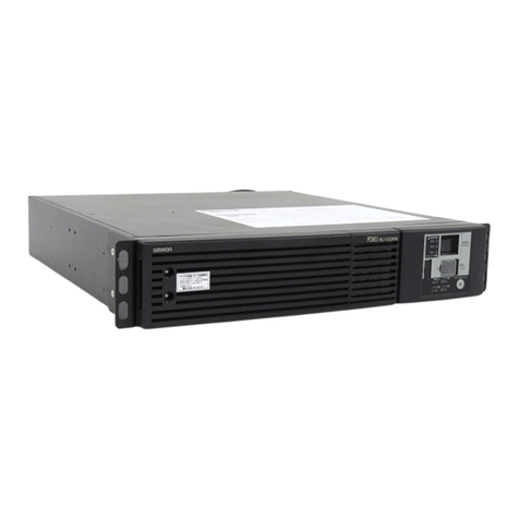
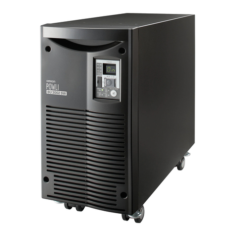
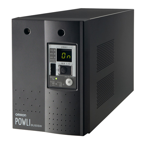
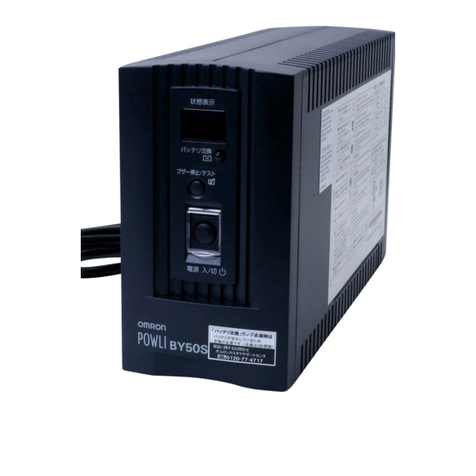
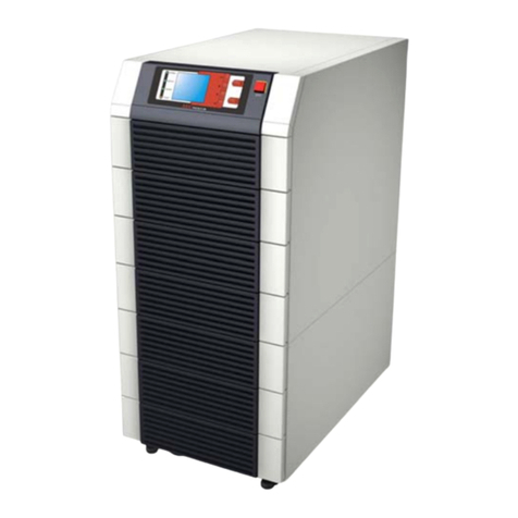
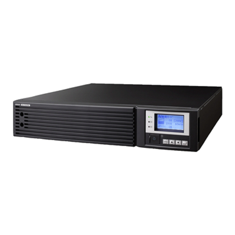
Omron POWLI BU100XR2 User manual

*Read this instruction manual before the installation and use of BU100XR2/ BU200XR2 because it gives
you the critical do's and don'ts of the devices.
*Keep this instruction manual within easy reach where you will install BU100XR2/BU200XR2 so that you
can read it whenever necessary.
No part or whole of this manual may be reproduced without permission.
The contents of this manual are subject to change without notice.
BU100XR2 / BU200XR2
Uninterruptible Power Supply (UPS)
Instruction Manual

Introduction
Thank you for purchasing Omron's Uninterruptible Power Supply (UPS).
•The UPS protects computers and other devices from surge voltage (a phenomenon in which extraordinary
high voltage occurs instantaneously) caused by power failures, voltage variations, instantaneous voltage
drops and power failures, and thunders.
•Under usual service conditions, the UPS converts commercial power into a direct current, and reconverted
from the direct current to the 100-VAC output of stable sine wave.
When detecting a failure of commercial power, the UPS switches itself to the uninterruptible power supply
mode, and feed the output of a sine wave through devices linked to the UPS.
The UPS is especially useful where power supply conditions are bad (for example, large voltage variations).
•Output capacities are 1KVA/700W for BU100XR2 and 2KVA/1.4KW for BU200XR2.
•The UPS provides the function of the Network Line Surge Protection to protect communications apparatus
such as modems from surge voltage that comes through the line (a phenomenon in which extraordinary
high voltage occurs instantaneously).
Notes on the use of the Backup UPS
• The UPS is designed and manufactured for OA equipment such as personal computers.
Do not use the UPS with the devices that require very high reliability and safety as listed below.
◊Medical devices that may cause death directly
◊Particular applications of devices that may cause injury (applications that directly affect the operation
and control of planes, ships, railroads, elevators, and others)
◊Applications that are always subjected to vibration such as cars and ships
◊Applications in which a failure of the UPS may cause critical damage or effect on public safety (major
computer systems, main communications equipment, public transportation systems, and others)
◊Devices with the similar level of importance
• For the devices that adversely affect the safety of people and maintenance of utilities in the event of
failure, special considerations related to operation, maintenance, and management of the system must
be taken such as a standby system for emergency use and an auxiliary power generator.
• Observe the do's and don'ts of this instruction manual related to the operating and environmental
conditions.
• When you want to add the UPS to the critical system that requires very high reliability, contact us; ______.
• Do not modify/alter your UPS.
• The UPS is tailored to a domestic use only. Do not use the product abroad (outside Japan).
◊Voltages and frequencies may differ abroad and may cause a failure and/or fire.
© OMRON Corporation. 2002 All Right Reserved.

1
IMPORTANT SAFETY INSTRUCTION
1. SAVE THESE INSTRUCTIONS.
This manual contains important instruction for Model BU100XR2/BU200XR2.
That should be followed during instruction of the UPS and batteries.
2. SYMBOL
This symbol indicates earth ground.
This symbol indicates turining on UPS.
This symbol indicates turining off UPS.
3. INTERNAL BATTERY.
Internal battery voltage is 36Vdc for BU100XR2, 72Vdc for BU200XR2.
4. TEMPERATURE RATING.
Maximum ambient temperature of UPS 40°C.
5. ENVIRONMENT
The unit is intended for installation in a temperature controlled, indoor area
free of conductive contaminants.

2
Table of Contents
Table of Contents
Introduction
IMPORTANT SAFETY INSTRUCTION .............................................................................................................. 1
Directions for safe use ....................................................................................................................................... 3
1. Preparation .................................................................................................................................................... 9
1-1 Unpacking the UPS ............................................................................................................................. 9
1-2 Checking the accessories ................................................................................................................... 9
1-3 Exterior features ................................................................................................................................ 10
1-4 Explanetion of symbol used on unit................................................................................................... 11
2. Installation and connection .......................................................................................................................... 12
2-1 Precautions and notes on installation and connection ...................................................................... 12
2-2 Installation ......................................................................................................................................... 14
2-3 Connecting and modifying AC input cable......................................................................................... 16
2-4 Connecting a battery unit (BU200XR2) ............................................................................................. 17
2-5 Adding a battery unit (BU100XR2, BU200XR2) ................................................................................ 18
2-6 Adding the UPS output receptacle (BU200XR2) ............................................................................... 18
2-7 Connecting method of devices .......................................................................................................... 19
2-8 Checking the operation ..................................................................................................................... 21
2-9 Charging the battery .......................................................................................................................... 23
2-10 Measuring the backup time .............................................................................................................. 23
3. Operating the UPS ..................................................................................................................................... 24
3-1 Precautions and notes on operation .................................................................................................. 24
3-2 Start and stop procedures ................................................................................................................. 26
3-3 Beep and display ............................................................................................................................... 27
4. Functions of the UPS ................................................................................................................................. 30
4-1 Suspending a beep ........................................................................................................................... 30
4-2 Testing the UPS (executing the self-diagnostic test) .........................................................................30
4-3 Description of the auto battery tests .................................................................................................. 31
5. Measuring the backup time .......................................................................................................................... 32
5-1 Measuring method of the backup time .............................................................................................. 32
5-2 Estimated backup time ...................................................................................................................... 32
6. Maintenance and inspection ....................................................................................................................... 33
6-1 Checking the battery ......................................................................................................................... 33
6-2 Replacing the battery ........................................................................................................................ 33
6-3 Cleaning ............................................................................................................................................ 40
6-4 Cautions at the maintenance of devices connected to the UPS ....................................................... 40
7. Using the Network Link Surge Protection Function .................................................................................... 41
7-1 When connecting to the telephone line or ISDN line ......................................................................... 41
7-2 When connecting to LAN 10Base-T/100 Base-Tx ............................................................................. 41
7-3 Example of connection ...................................................................................................................... 42
8. Using the UPS monitoring software and contact signal I/O ........................................................................ 43
8-1 RS232C • Contact signal I/O ............................................................................................................. 43
8-2 When performing the auto shutdown processing by the UPS monitoring software .......................... 43
8-3 When performing the auto shutdown processing by the UPS Service of WindowsXP/2000 ............ 44
8-4 When performing the auto shutdown processing by the UPS Service of WindowsNT ..................... 45
8-5 Details on Contact Signal I/O ............................................................................................................ 45
8-6 Precautions and notes on the use of the Contact Signal I/O ............................................................. 46
9. Changing the setting of the functions ........................................................................................................... 47
9-1 Functions that can be set/change from the UPS ............................................................................... 47
9-2 Functions that can be set/change from the UPS monitoring software .............................................. 48
10. Troubleshooting ......................................................................................................................................... 49
A. Specifications ......................................................................................................................................... 50
B. Dimensional outline drawings ................................................................................................................ 51
C. Circuit block diagram ............................................................................................................................. 52
D. Optional parts and products ................................................................................................................... 52

3
Directions for safe use
Misuse may cause death or serious injury.
Warning
Caution
Directions for safe use
●The safety symbols and their meaning used in this manual are as follows.
* Property damage means damage to houses/household effects, livestock, and pets.
Notice that do's and don'ts of "Caution" may bring about a serious accident according to the circumstances.
These do's and don'ts are critical and must be observed strictly.
Warnings
Read this instruction manual before the installa-
tion and use because it gives you the critical do's
and don'ts of your UPS.
Misuse may cause injury or property damage.
Do not disassemble, repair, and/or modify your UPS.
●Doing so may cause an electric shock or fire.
If battery liquid leaks from the UPS, do not touch it.
●Doing so can lead to blindness and/or or burns.
●If the liquid gets in eyes or spills on your skin, wash them with clean water and see a doctor.
An electric shock or short may occur
●Do not put you hand into the opening of the battery when replacing the battery.
●Do not insert a metal thing into the inside of the battery.
Unpack and carry out the UPS bearing the weight in mind. Place and run
the UPS on a structurally sound base.
●Toppling and dropping may cause injury.
●The weight of the UPS
BU100XR2: 19kg BU200XR2: 12kg (main unit)
MB100XR2: 26kg (add-on battery unit) MB200XR2: 26kg (battery unit)
Keep packing materials including plastic bags and films out of the reach
of children
●When children swallow or put their head into the packing material, it may bring about the
danger of suffocation.
Do not add the UPS where very high reliability and safety are required as
listed below. (The UPS is designed and manufactured for uses of OA
equipment, such as personal computers.)
●Medical devices and/or system that may cause death directly
●Applications that may adversely affect the safety of people (for example, the operation and control of auto-
mobiles and elevators)
●Applications that adversely affect the maintenance of utilities in the event of failure (for example, critical
computer systems and trunk lines)
●Applications with the similar level of importance
Warnings (uses of the UPS)
:Indicates prohibition (don'ts). For example, indicates that disassembly is prohibited.
:Indicates compulsory (do's). For example, indicates that grounding is a must.
Cautions (installation)

4
Directions for safe use
Provide secure grounding
●Earth the ground terminals of the UPS and devices connected to the UPS. (See "2. Installation
and connection" on page 12)
You may receive an electric shock in the event of trouble or power failure. When both the UPS
and devices are not grounded and touch both, you may receive an electric shock.
●When you use a 3-pin to 2-pin adaptor for an AC Input Plug, be sure to perform grounding before putting the
AC Input Plug in a wall outlet (commercial power). On the other hand, be sure to perform disconnecting a
grounding terminal after removing the AC Input Plug from a wall outlet (commercial power).
●Connect the UPS grounding terminal to a grounded-type wall outlet (commercial power) to make working
the Power Line Surge Protection and the Network Line Surge Protection as intended.
Do not use the UPS where the maximum temperature exceeds 40°C.
●An battery deterioration will occur rapidly and may cause a fire.
●Doing so may cause a failure or malfunction of the UPS.
Do not install or store the UPS in the places as listed below.
●The humidity is lower than 10%. The humidity is higher than 85%. An enclosed space such as
a cabinet with no crevice. Near flammable gas and/or corrosive gas. Outdoors.
●Doing so may cause a fire.
Do not obstruct the air inlets and outlets on the upper and rear sides of
the UPS.
Do not place the UPS in an enclosed space or put a cover the UPS.
●Doing so may lead to an abnormal overheat or fire.
●Temperature will increase inside the UPS and may cause a failure of the UPS and battery
deterioration.
●Install the UPS 5cm away from the wall or further.
Do not install the UPS in the other orientations.
Do not install the UPS on a structurally unsound base.
●See "2-2 Installing" on page 12.
●Toppling and dropping may cause injury.
When you want to install your UPS horizontally, secure the supplied rubber
seats in the four corners of the underside of the UPS.
●Toppling and/or dropping may occur and cause injury.
Be sure to use supplied mounting screws.
●Other screws rather than supplied screws may cause dropping due to insufficient strength.
In a case where the UPS is to be mounted on a rack, place it on the lowest
part of the rack.
●Dropping may cause injury.
●The weight of the UPS
BU100XR2: 19kg MB100XR2: 26kg (add-on battery unit)
BU200XR2: 12kg (main unit) MB200XR2: 26kg (battery unit)
Do not install the UPS alone but ask your colleagues for help.
●Dropping may cause injury.
Cautions (installation)
Plug the UPS in a wall outlet (commercial power) with a current capacity
larger than the maximum input current of the UPS.
●Otherwise, the power cord may be heated.
●For the device that requires power equivalent to the current capacity of the UPS or larger,
BU100XR2 feeds 10.2A while BU200XR2 feeds 20A.
Cautions (connection)

5
Directions for safe use
Be sure to put the input plug of the UPS in a 100VAC (50/60Hz) wall outlet
(commercial power).
●Putting the input plug in a wall outlet (commercial power) of a different voltage may cause a
fire.
●The UPS may fail.
Do not connect devices that exceed the output capacity of the UPS.
You can add extra devices with a plug strip. Note that the plug strip does
not permit to plug in the device, which exceeds the current capacity of
the plug strip.
●The UPS may detect overload and stop the output.
●The plug strip cord may heat up and could lead to a fire.
Cautions (connection)
In a case where the Battery Replacement Lamp comes on or the backup
time becomes shorter than the required backup time, replace with a new
battery pack while the UPS is running, or stop the UPS and discard the
old battery pack.
●The continuous operation of the UPS may cause a fire.
●For further information on how to inspect the battery, see "6. Maintenance and inspection" on
page 33.
In case where you notice abnormal sound or smell, smoke, or liquid from
the inside of the UPS, press the Stop switch of the UPS immediately and
remove the AC Input Plug from a wall outlet (commercial power).
●A continuous operation under the abnormal conditions may cause a leakage of current or fire.
●If you notice the abnormal conditions, never operate the UPS and contact the distributor from
which you purchased your UPS or us for inspection and repair.
●Your UPS must permit to remove AC Input Plug from a wall outlet (commercial power) instantly
at the onset of a failure.
When the input plug accidentally become removed while the UPS is
running, never touch the metal part of the input plug.
●Doing so may cause an electric shock.
●A leak current of the UPS is less than the value of safety standard (leak current: 1mA) how-
ever, the leak current may increase due to the devices connected. Therefore, never touch the
metal part of the input plug.
Cautions (use)
*The left table shows the estimated life expectancy of
a battery pack on the ground that the battery is used
in the usual way. They are not the warranty period.
Ambient temperature
20°C
30°C
Estimated life expectancy
4 to 5 years
2 to 2.5 years

6
Directions for safe use
Do not place things on the UPS or do not drop metal things into the UPS.
●Doing so may cause distortion and/or damage to the top case of the UPS or an internal circuit
failure, which may leads to a fire.
Do not place the UPS in an enclosed space or put a cover over the UPS.
●Doing so may lead to an abnormal overheat or fire.
Do not wet or spill water on the UPS
●Doing so may cause an electric shock or fire.
Do not insert a metal thing into the Power Supply Output receptacle of the
UPS.
●Doing so may cause an electric shock.
Do not insert metal things into the battery connector or add-on battery
connector.
●Doing so may cause an electric shock.
Cautions (use)
Before maintaining devices connected to the UPS, turn off the UPS and
remove the AC Input Plug from a wall outlet (commercial power).
●Even if you remove the AC Input Plug during the operation of the UPS, the backup function of
the UPS keeps feeding power through the power supply output receptacle of the UPS.
●In a case where the scheduled operation is ON and the AC Input Plug of the UPS is put in a wall outlet
(commercial power), the UPS starts feeding power at the starting time of the scheduled operation.
Cautions (maintenance)
Do not short the battery with a metal thing.
●Doing so may cause a burn or fire.
●A dead battery keeps some current remaining.
Do not toss a battery into the fire. Do not try to break a battery.
●The battery may explode or dilute sulfuric acid may leak.
Do not use any batteries unless otherwise specified.
●Doing so may lead to a fire.
●Battery model: BP100XR
Do not use a new battery and an old battery all together
●Dilute sulfuric acid may leak
Do not drop the battery or do not give strong impact on it.
●Dilute sulfuric acid may leak.
Do not replace the battery near the place where there is flammable gas.
●A spark may occur when connecting the battery, and lead to a fire.
Replace a battery on a structurally sound base.
●Hold the battery securely with your both hands to avoid dropping.
●Not doing so may cause injury due to failing, burns, or liquid (acid) leakage.
Do not carry the replaced battery pack upside down.
●If liquid (dilute sulfuric acid) leaks from the battery, there is a danger of burns or blindness.
Do not disassemble or modify the battery.
●Doing so may cause a leakage of dilute sulfuric acid, which may cause blindness and burns.
Cautions (battery replacement)

7
Directions for safe use
Notes
Charge the battery (for at least 8 hours) immediately after purchasing the UPS.
●If you do not use your UPS for a long time after purchasing, the battery characteristic may deteriorate and
become unusable.
●After putting the AC Input Plug of the UPS in a wall outlet (commercial power), the battery is automatically
charged.
When you want to store the UPS, charge the battery for at least 8 hours.
●In a case where you do not use the battery, it discharges spontaneously and gets into over discharge status
after it is left for a long time. The backup time may become shorter or the battery may become unusable
●The expiration date of the battery installed in the UPS is 6 months after charging it for at least 8 hours.
●If you want to store the battery longer than 6 months, put the AC Input Plug of the UPS in a wall outlet
(commercial power) for at least 8 hours before the expiration date is exceeded.
●Press the stop switch of the UPS for storage.
Do not reverse the connection of Line/Hub Side and Modem/TA/PC Side of the Network
Line Surge Protection.
●If a protection circuit failure occurs, the line side (telephone/ISDN line) may be damaged.
Do not give a short between the output lines of the UPS, as well as a
ground fault between the output lines and the ground.
●The UPS may fail.
Do not put the AC Input Plug of the UPS in the Power Supply Output Receptacle of
the UPS.
●The UPS may fail.
Turn off the UPS before opening a circuit breaker or removing the AC Input Plug
from a wall outlet (commercial power).
If you cannot stop the UPS for some reason, bring the UPS to automatic stop through
the UPS monitoring software, which requires the least backup time.
●You can start the backup mode of the UPS simply by cutting off commercial power to the UPS and keep
devices running until the battery gets discharged. That way when you repeat charges and discharges
many times, the life expectancy of a battery pack becomes extremely short.
The less you repeat charges and discharges, the longer the life expectancy of the battery will become.
Do not connect a page printer to the UPS.
●In a case a page printer is connected to the UPS, the amount of output current often exceeds the current
output capacity of the UPS in the commercial power operating mode, and that may lead to the UPS to put
out a feed power as it is (bypass mode).
●The peak current of the page printer is large so that it may be detected as an overcurrent.
Do not perform a withstand voltage test.
●The power input circuit has a built-in surge absorber element. A withstand voltage test may break it.
●When performing an insulation resistance test, select the 250 VDC range.

8
Directions for safe use
Explanations
Usual operating method
●You may keep the UPS running without making a stop, or you may turn off the UPS at each time when the
devices connected the UPS is turn off.
You can choose either of two ways at your convenience.
●Putting the UPS to a wall outlet (commercial power) starts charging the battery.
Terminating the backup mode
●In a case where power failure continues longer, the battery keeps its discharging and finally the UPS stops
sending power. Before that, turn off your computer in the usual manner (including data backup).
Reboot
●If the battery discharges completely during a power failure, the UPS stops. After the recovery from a failure
of the power supply (for example, power failure), the UPS automatically restarts and starts to feed power. If
you do not want to run the devices connected to the UPS, keep turning the devices off.
●The UPS monitoring software permits to disable automatic restart.
Scheduled operating mode through the UPS monitoring software
●When performing scheduled operating mode in which the UPS is turned off and the commercial power is cut
off by using a circuit breaker at the same time, specify a less than 3 months shutdown. In a case that you
specify the shutdown longer than 3 months, the internal timer will be reset and the scheduled operating
mode will not work.
Notice that a shutdown should reduce to approximately half where the battery is dead.
In a case where a shutdown exceeds 3 months, the UPS starts to feed commercial power and you can get
the UPS running by pressing the Start switch. However, if the battery is already dead, you may not be able
to start the UPS. Then replace the battery according to "6-2 Replacing the battery" on page 33.
Installing a rack
●For safety installation, placing a rail or steel plate is recommended to support the weight of the USP.
●The weight of the UPS
BU100XR2: 19kg BU200XR2: 12kg (main unit)
MB100XR2: 26kg (add-on battery unit) MB200XR2: 26kg (battery unit)
●Place the UPS on the lowest part of lack. When connecting the battery unit and/or adding another battery
unit, be sure to place the battery unit on the lower part of main unit.
Notes
Recycling and Discarding the Battery
●The UPS has a lead acid battery. The battery is recyclable, and precious resource. We need
your cooperation in recycling the old batteries; the batteries you replace with a new battery,
and the batteries you used to discard.
●For further information on recycling and/or discarding of batteries and UPS, please contact us;_________.
Installation and storage places
●Do not install or store the UPS in a place exposed to direct sunlight.
The rise of temperature may cause the battery to deteriorate and become unusable.
Pb

9
1. Preparation
BU100XR2
1. Instruction Manual
(English and Japanese versions)
.... 1 each
2. Telephone cable (modular cable) ................................... 1
3. Warranty card ........................................................... 1
4. User registration card............................................... 1
5. 3P-2P adaptor .......................................................... 1
6. Upright stand ........................................................... 2
7. AC input cable ......................................................... 1
8. 19-inchrackmount fittings (6 screws) ....................... 2
9. Rackmount bolts and nuts .............................. 4 each
10. "Identification of operating condition" label .............. 1
BU200XR2 (main unit)
1. Instruction Manual
(English and Japanese versions)
.... 1 each
2. Telephone cable (modular cable) ............................ 1
3. Warranty card ........................................................... 1
4. User registration card............................................... 1
5. 3P-2P adaptor .......................................................... 1
6. 15A output receptacle .............................................. 1
7. 19-inch rackmount fittings (6 screws) ............. 2 each
8. Rackmount bolts and nuts .............................. 4 each
9. "Identification of operating condition" label .............. 1
10. Fuse (for Output 20A) ............................................... 1
11. AC input terminal cover............................................ 1
MB200XR2 (battery unit)
1. Instruction Manual
(English and Japanese versions)
.... 1 each
2. Battery connecting cable ......................................... 1
3. 19-inch rackmount fittings (6 screws) ...................... 2
4. Rackmount bolts and nuts .............................. 4 each
UPS monitoring software
(Attached to the BU100XR2/BU200XR2)
1. Instruction Manual .................................................... 1
2. Installation CD-ROM ................................................. 1
3. Connecting cable (9-pin serial cable) ...................... 1
4. User registration card............................................... 1
Care must be taken on unpacking of BU100XR2 as the built-in battery leans the center of gravity of BU100XR2
to one side.
Unpack and carry this product bearing the weight in mind. Place and
run the UPS on a structurally sound base.
●Toppling and dropping may cause injury.
●The weight of the backup UPS
BU100XR2: 19kg BR200XR2: 12kg (main unit)
MB100XR2: 26kg (add-on battery unit) MB200XR2: 26kg (battery unit)
1-2 Checking the accessories
If you should notice defects or anything wrong, please contact your distributor at once.
Cautions
1. Preparation
1-1 Unpacking the UPS
Installation CD-ROM
Connecting cable
Telephone cable
(modular cable)
3P-2P adaptor
TUpright stand
AC input cable
19-inch rackmount
fittings
Rackmount bolts
and nuts
3P-2P adaptor
Telephone cable
(modular cable)
15A output receptacle
19-inch
rackmount
fittings
Rackmount bolts
and nuts
19-inch
rackmount
fittings
Battery connecting
cable
Rackmount bolts
and nuts
Fuse
(
φ
6.35x32mm)
AC input
terminal cover

10
1. Preparation
1-3 Exterior features
This section shows the external parts of the UPS.
For information on the function of each part, see "2. Installation and connection" on page 9 and "3. Operating
the UPS" on page 24.
BU100XR2/BU200XR2
● (Main unit) front view ● BU1OOXR2 rear view
[Enlarged view of the display]
● BU2OOXR2 rear view
バックアップ
運転
AC入力
バイパス
運転
バッテリ
残量
テスト/ブザー停止
電源出力
異常
接続容量
オーバー
バッテリ
交換
入力15A
オーバー
運転
停止
Signal Card
Expansion Slot
Add-on Battery
Connector
Network Surge
Protection
AC Input Overcurrent
Grounding Terminal
RS232C/signal
I/O connector
AC Input
Connector Power Supply Output
Receptacles (Backup is
carried in the event of a
power failure)
Air Outlet
Power Supply Output
Receptacles (Backup is
carried in the event of a
power failure)
RS232C/
signal I/O
connector
Signal Card
Expansion Slot
Output fuse (20A)
AC Input
Terminal
Network Surge
Protection
AC Input Overcurrent
Protection
Air Outlet
Battery Connector
A. AC Input Lamp
B. Bypass Mode Lamp
C. Backup Mode Lamp
D. Power Supply Output Lamp
E. Start Switch
F. S t op Switch
G. Battery Indicator
H. Connection Capacity Lamp
I. Error Lamp
J. Connection Capacity
Exceeded Lamp
K. Battery Replacement Lamp
L. Input 15A Exceeded Lamp
(BU200XR2 only)
M. Connection Capacity/Battery
Level Meter

11
1. Preparation
MB200XR2 (battery unit)/MB100XR2 (Add-on battery unit)
Front view Rear view
接続
Connecting
lamp
[Enlarged view of the display]
Battery connector
Add-on battery connector
(MB200XR2 only)
1-4 Explanetion of symbol used on unit
Symbol Description
Start the UPS.
Stop the UPS.
Suspend a beep.
Expanding battery unit connecting to the UPS. (For BU100XS only.)
UPS has Error.
Connected Overload. Excess output capacity by connected devices.
Batteries in end of useful life, necessary to replace the batteries.
AC input current over 15A.
AC input / output power supplied.
Indicates earth ground.

12
2. Installation and connection
Cautions (Compulsory (do's))
2. Installation and connection
2-1
Precautions and notes on installation and connection
Precautions and notes on installation and connection are given below. Be sure to read them for correct use.
Unpack and carry the UPS bearing the weight in mind. Place and run the
UPS on a structurally sound base.
●Toppling and dropping may cause injury.
●The weight of the UPS
BU100XR2: 19kg BR200XR2: 12kg (main unit)
MB100XR2: 26kg (add-on battery unit) MB200XR2: 26kg (battery unit)
Keep packing materials including plastic bags and films out of the reach
of children
●When children swallow or put their head into the packing material, it may bring about the
danger of suffocation.
Provide secure grounding
●Earth the ground terminals of the UPS and devices connected to the UPS. (See "2. Installation
and connection" on page 12)
You may receive an electric shock in the event of trouble or power failure.
When both the UPS and devices are not grounded and touch both, you may receive an electric
shock.
●When you use a 3-pin to 2-pin adaptor for an AC Input Plug, be sure to perform grounding
before putting the AC Input Plug in a wall outlet (commercial power). On the other hand, be
sure to perform disconnecting a grounding terminal after removing the AC Input Plug from a
wall outlet (commercial power).
●Connect the UPS grounding terminal to a grounded-type wall outlet (commercial power) to
make working the Power Line Surge Protection and the Network Line Surge Protection as
intended.
Plug the UPS in a wall outlet (commercial power) with a current capacity
larger than the maximum input current of the UPS.
●Otherwise, the power cord may be heated.
●For the device that requires power equivalent to the current capacity of the UPS or larger,
BU100XR2 feeds 10.2A while BU200XR2 feeds 20A.
Be sure to put the AC Input Plug of the UPS in a wall outlet (commercial
power) of 100VAC (50/60Hz).
●Putting it in a wall outlet (commercial power) of a different voltage may cause a fire.
●The UPS may fail.
Be sure to use supplied mounting screws.
●Other screws rather than supplied screws may cause dropping due to insufficient strength.
When you want to install your UPS horizontally, secure the supplied rubber
seats in the four corners of the underside of the UPS.
●Toppling and/or dropping may occur and cause injury.

13
2. Installation and connection
Notes
For safety installation, placing a rail or steel plate is recommended to support the
weight of the USP.
●The weight of the UPS
BU100XR2: 19kg BU200XR2: 12kg (main unit)
MB100XR2: 26kg (add-on battery unit) MB200XR2: 26kg (battery unit)
Place the UPS on the lowest part of lack.
●When connecting the battery unit and/or adding another battery unit, be sure to place the battery unit on the
lower part of main unit.
Do not give a short between the output lines of the UPS, as well as a ground fault
between the output lines and the ground.
●The UPS may fail.
Do not put the AC Input Plug of the UPS in the Power Supply Output Receptacle of
the UPS.
●The UPS may fail.
Do not connect a page printer to the UPS.
●In a case a page printer is connected to the UPS, the amount of output current often exceeds the current
output capacity of the UPS in the commercial power operating mode, and that may lead to the UPS to put
out a feed power as it is (bypass mode).
●The peak current of the page printer is large so that it may be detected as an overcurrent.
Cautions (Prohibition (don'ts))
Do not obstruct the air inlets and outlets on the upper and rear sides of
the UPS.
Do not place the UPS in an enclosed space or put a cover the UPS.
●Doing so may lead to an abnormal overheat or fire.
●Temperature will increase inside the UPS and may cause a failure of the UPS and battery
deterioration.
●Install the UPS 5cm away from the wall or further.
Do not use the UPS where the maximum temperature exceeds 40°C.
●An battery deterioration will occur rapidly and may cause a fire.
●Doing so may cause a failure or malfunction of the UPS.
Do not install or store the UPS in the places as listed below.
●The humidity is lower than 10%. The humidity is higher than 85%. An enclosed space such as
a cabinet with no crevice. Near flammable gas and/or corrosive gas. Outdoors.
●Doing so may cause a fire.
Do not connect devices that exceed the output capacity of the UPS.
You can add extra devices with a plug strip. Note that the plug strip does
not permit to plug in the device, which exceeds the current capacity of
the plug strip.
●The UPS may detect overload and stop the output.
●The plug strip cord may heat up and could lead to a fire.
Do not install the UPS in the other orientations.
Do not install the UPS on a structurally unsound base.
●See "2-2 Installing" on page 12.
●Toppling and dropping may cause injury.

14
2. Installation and connection
2-2 Installation
The UPS permits the following installing methods according to its surroundings.
1. Rackmount installation
2. Stationary installation
1. Rackmount installation (JIS/EIA 19-inch rack/sever rack)
Cautions
In a case where the UPS is to be mounted on a rack, place it on the
lowest part of the rack.
●Dropping may cause injury.
●The weight of the UPS
BU100XR2: 19kg MB100XR2: 26kg (add-on battery unit)
BU200XR2: 12kg (main unit) MB200XR2: 26kg (battery unit)
Do not install the UPS alone but ask your colleagues for help.
●Dropping may cause injury.
(1) Mount supplied 19-inch rackmount fittings on both sides
of the UPS with 6 screws (M4 X 6mm steel countersunk
screws).
(2) Unscrew the rubber seats counterclockwise installed in
the four corners of the underside and remove them all.
(3) •The installation of the UPS on 19-inch rack.
a. Remove the supplied rackmount screws (M5 X 15cm
steel pan head screws).
b. Screw the UPS to the rack keeping it in a horizontal
position. Exercise care to avoid creating clearance
between the fittings and rack.
•The installation of the UPS on a server rack
a. Remove the secured rackmount screws (M5 X 15cm
steel pan head screws).
b. Install rackmount nut on the rack.
c. Screw the UPS to the rack keeping it in a horizontal
position. Exercise care to avoid creating clearance
between the fittings and rack.
In a case where the UPS is to be mounted on a rack, place it on the
lowest part of the rack.

15
2. Installation and connection
Upright position
*When you install the UPS in the
upright position, be sure to
install the upright stand on the
left side of the UPS. (To position
heavy components on the lower
part of the UPS)
*An add-on battery unit does not
permit the upright position.
*When connecting the battery and/or
adding another battery, be sure to
place the battery below
Horizontal position
2. Stationary installation
The UPS permits the following positions shown in the illustrations only.
●Horizontal position
Place the UPS with the factory-mounted rubber seats side down. (Mounting screws: M4 X 6mm)
●Upright position (BU100XR2 only)
Install the supplied upright stand to the UPS.
Great care should be taken to install upright stand on the left
side of the UPS.

16
2. Installation and connection
2-3 Connecting and modifying AC input cable
●BU100XR2
Connect "AC Input Cable" to "AC Input Connector" of
BU100XR2.
●BU200XR2
1. AC Input Cable modification (In a case where input current exceeds 15A)
In a case where input current exceeds 15A ("Input 15A Exceeded" LED on the front panel will light up), pull
out the AC Input Cable from BU200XR2. Next, contact an electrician (a qualified electrician; Type II or
higher) to lay the AC Input Cable directly to a power switchboard.
•The current capacity must be over 20A. (a cable of 3.5mm2or larger nominal cross section area is
recommended)
•Insert 100AVC cable between L and N of "AC Input Terminal." Connect the ground cable to G of "AC Input
Te r mi nal."
•Requirement for Terminal Block
The wire size based on the ampacities given in the National Electrical Code, ANSI/NFPA 70-1993,and the
derating factor described in Underwriters Laboratories Inc., Standerd for Safety UL1778-1994.
•AC Input Cable Replacement
(1) Remove the terminal-cover at AC input. (Two screws)
(2)
Remove screws at terminals (L, N, G) connecting the cable to the terminals and remove the old AC input cable.
(3) Set the attached new AC input terminal-cover to the new AC input cable.
(4) Connect the new AC input cable to AC input terminals by screws.
Be careful to polarities of L, N, G terminals and connect correctly.
AC Input
Connector
AC Input Cable
Temperature rating of wire
intended to be used for
connection of unit
Min.60°C
Copper Conductors Only
Use No.12 AWG 60°C or
75°C copper wire
Tightening torque
Approx 13.8 Lb-In
unscrew these
Terminal-cover
L
N
G
Use the new AC input terminal-cover
attached to the new cable.
Connect to AC input terminals by screws.

17
2. Installation and connection
(5) Fix the AC input terminal-cover to the console by screws.
2. How to calculate an input current roughly
You can calculate an input current roughly before turning on the UPS.
•Calculate the total electric energy (VA) of the devices linked to the UPS.
Get volt-ampere (VA) of the devices connected to BU200XR2. You may refer to their rating plate, specification
sheet, and instruction manual. Finally sum the amount of VA
In a case where VA is described as W (watt), perform mathematical calculations; W ÷0.6 = ___VA.
In a case where VA is described as A (ampere), perform mathematical calculations; A X 100 = ___VA.
•In the event that resultant total volt-ampere exceeds 1500VA, change the AC Input Cable.
Explanation
When reconnect AC Input Cable to BU200XR2, align "L,N,G" printed on the right side of AC Input Terminal,
which is on the rear side of BU200XR2, with "L,N,G" printed on AC Input Cable.
Screw the terminal-cover
2-4 Connecting a battery unit (BU200XR2)
When connecting "Battery Connecting Cable" included with the battery unit between "Battery Connector" of the
main unit and "Battery Connector" of the battery unit, it may make a spark, however, that is no problem. After
putting "AC Input" plug in, the connection lamp on the front panel of the battery unit will light up.
BU200XR2
MB100XR2

18
2. Installation and connection
2-5 Adding a battery unit (BU100XR2, BU200XR2)
2-6 Adding the UPS output receptacle (BU200XR2)
When two UPS output receptacles are not enough
and an additional receptacle is needed, simply
connect a supplied 15A output receptacle to the
"power supply output receptacle of the main unit."
Secure the 15A output receptacle on the rear side of
the battery unit with screws (M4 X 6mm, inch-thread
screws)
●BU200XR2
Connect a "Battery Connecting Cable" included with
the battery unit between the "Battery Add-on
Connector" of BU200XR2 and the "Battery Connector"
of an add-on battery unit. After putting an "AC Input"
plug in, a "Connection" lamp on the front panel of the
battery unit will light up. BU100XR2 permits up to two
ad-on battery units.
●BU100XR2
Connect a "Battery Connecting Cable" included
with the battery unit between the "Battery Add-
on Connector" of BU100XR2 and the "Battery
Connector" of the battery unit. After putting an
"AC Input" plug in, a "Connection" lamp on the
front panel of the battery unit will light up.
BU100XR2 permits only one ad-on battery unit.
* For further information, see the instruction
manual of Battery Unit.
* For further information, see the instruction manual of
Battery Unit.
BU200XR2
MB200XR2
BU100XR2
Add-on
battery unit
MB100XR2
Add-on
battery unit
MB200XR2
Add-on
battery unit
MB200XR2
A backup time is 20 minutes in a case where
a 1KVA/700W device is connected. (ambient
temperature: 20°C, battery initial value) A
discharged battery requires twenty-four
hours to recharge fully.
The backup time is 10 minutes in a case where a
2KVA/1.4KW device is connected with one add-on
battery, and 20 minutes with two add-on batteries.
(ambient temperature: 20°C, battery initial value) A
discharged battery requires twelve hours to
recharge fully in the case of one add-on battery,
while it requires twenty-four hours in the case of
two add-on batteries.
This manual suits for next models
1
Table of contents
Other Omron UPS manuals

Omron
Omron POWLI BY50FW User manual

Omron
Omron POWLI BU50XS User manual

Omron
Omron POWLI BN100XR User manual

Omron
Omron S8BA-24D24D120LF User manual

Omron
Omron BN75R User manual

Omron
Omron BU150R User manual

Omron
Omron BU2002RWL User manual

Omron
Omron Powli BU50SW User manual

Omron
Omron POWLI BN50S User manual

Omron
Omron Powli BY35S User manual

Omron
Omron BW40T User manual

Omron
Omron BUM100R User manual

Omron
Omron S8BA-S Series L User manual

Omron
Omron POWLI BU60RE User manual

Omron
Omron S8BA-24D24D960SBF User manual

Omron
Omron Powli BU75RW User manual

Omron
Omron BU1002RW User manual

Omron
Omron POWLI User manual

Omron
Omron S8BA-24D24D Series SBF User manual

Omron
Omron BN50T User manual