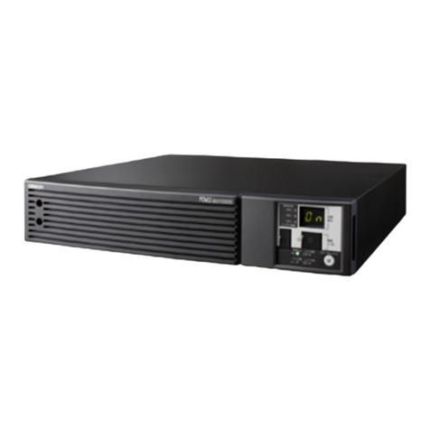
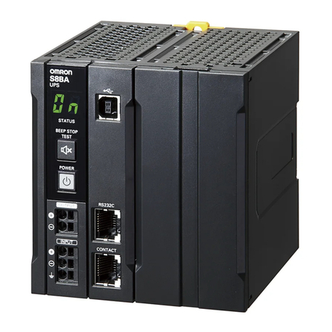
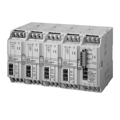
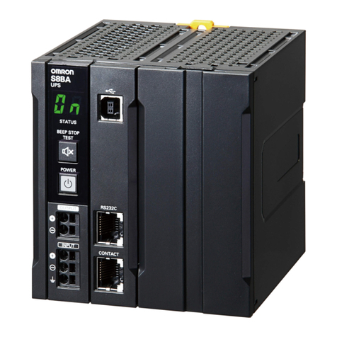
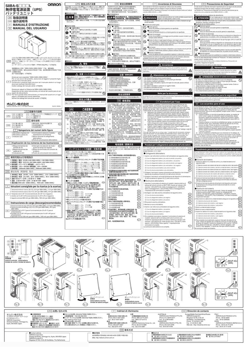
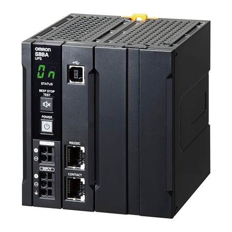
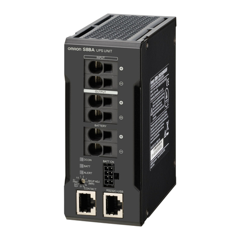
Omron S8BA LF Series User manual

1
Uninterruptible Power Supply (UPS)
Integrated battery type
S8BA-LF
DC-DC type small UPS mounts on a
DIN rail to provide an ideal
countermeasure for momentary power
losses and power failures in industrial
computers (IPC) and controllers.
• System reliability greatly improved because
24VDC power supply is backed up for a certain
period of time in the event of voltage drop or power failure.
• Compactness, weight reduction, and long battery life
realized thanks to the adoption of a lithium-ion battery.
• Push-in terminal block adopted for the power input and
output I/F.
• Shutdown in conjunction with the industrial
purpose computer (IPC) or controller realized
by the USB/RS-232C/I/O port installed in the UPS.
Model Number Structure
Model Number Legend * Use the following format to place an order.
Ordering Information
Main body
Uninterruptible Power Supply (UPS)
*16.7 A/400 W for use as a UL compliant device.
Communication cable
Replacement battery pack
Input voltage Output voltage Output current/capacity Model number
24 VDC 24 VDC
5 A/120 W S8BA-24D24D120LF
10 A/240 W S8BA-24D24D240LF
15 A/360 W S8BA-24D24D360LF
20 A/480 W * S8BA-24D24D480LF
Specifications Type Length Model number
For RS-232C port RJ45/Dsub9Pin 2 m S8BW-C01
For CONTACT port RJ45/Discrete wire S8BW-C02
Rated voltage Rated capacity Weight Model UPS Model : Required units
14.4 VDC 1600 mAh 0.3 kg S8BA-B120L
S8BA-24D24D120LF : 1 pcs
S8BA-24D24D240LF : 2 pcs
S8BA-24D24D360LF : 3 pcs
S8BA-24D24D480LF : 4 pcs
!Refer to Safety Precautions on page 13.
2 31
Series name
S8BA-
@@@@@@@@@LF
1. Input voltage specification
24D: 24 VDC
2. Output voltage
24D: 24 VDC
3. Capacity
120: 120 W
240: 240 W
360: 360 W
480: 480 W

S8BA-LF
2
Ratings, Characteristics, and Functions
*1. An estimated value for standard mounting. Not a guaranteed value.
*2. Conditions: With rated loads connected, at a rated input voltage, and with the battery fully charged.
*3. Conditions: With rated loads connected, at a rated input voltage, and at the maximum battery charging current.
*4. 400 W for use as a UL compliant device.
*5. 20 A for use as a UL compliant device.
*6. 16.7 A for use as a UL compliant device.
*7. When using in an environment at a high temperature, charging may be paused by charging temperature protection, then the charging time will
be longer than specified time.
"CS" will be displayed when charging temperature protection is operated.
*8. For the S8BA-24D24D120LF, install all of the RSMN-2030, RSHN-2030, and RSEN-2030 EMC filters manufactured by TDK. For the S8BA-
24D24D240LF, S8BA-24D24D360LF, or S8BA-24D24D480LF, install both the RSMN-2030 and RSHN-2030 or their equivalents. Install these
filters in series to the cable connected to the DC input terminal block.
When you do, do not connect anything to the GR terminal.
The effectiveness of the noise filters may be affected by the installation environment. Be sure to check effectiveness before starting operation.
Item Capacity 120 W 240 W 360 W 480 W *4
DC input
Rated input voltage 24 VDC
Input
voltage
range
When standard voltage
sensitivity is set 24 VDC±10%
When low voltage sensitivity
is set 24 VDC±12.5%
When high voltage
sensitivity is set 24 VDC±5%
Input
maximum
current
for rated input voltage for
rated loads connected 5.9 A 11.7 A 17.5 A 23.3 A *5
Input terminal Push-in terminal block
Input protection Fuse (cannot be replaced by the customer)
Input protection capacity 10 A 15 A 30 A
DC output
Rated
current (for rated output voltage) 5 A 10 A 15 A 20 A *6
Switching time Uninterrupted
Output
voltage
Normal operation Output of input voltage as-is
Backup operation 24 V±5%
Output terminal Push-in terminal block
Overload protection
Alarm display at a load level of 110% or over (normal operation)
Alarm display at a load level of 110% or over and output voltage drop (backup operation)
Alarm display cancellation at a load equal to or below the rated capacity (normal operation, backup
operation)
Battery
Type Lithium-ion battery
Rated voltage 14.4 VDC
Rated capacity 1600 mAh × 1 parallel 1600 mAh × 2 parallel 1600 mAh × 3 parallel 1600 mAh × 4 parallel
Expected battery life *1 2.5 years (50°C), 5 years (40°C), 10 years (25°C)
Replacement by user Yes (Hot swapping)
Auto battery check function Yes
Battery life counter function Yes
Charging time 4 hours *7
Backup time (25°C, initial characteristics) 6 min. (120 W) 6 min. (240 W) 6 min. (360 W) 6 min. (480 W)
Environment
Operating ambient temperature/humidity
0 to +55°C/10 to 90% (with no condensation)
Storage ambient temperature/humidity –20°to +55°C/10 to 90% (with no condensation)
Vibration resistance JIS C 60068-2-6 compliant. 5 to 8.4 Hz amplitude: 3.5 mm, 8.4 to 150 Hz acceleration rate: 9.8 m/s2
X, Y, and Z directions for 100 minutes (Time coefficient: 10 minutes × coefficient factor 10 = total time 100 min.)
Shock resistance JIS C 60068-2-27 compliant. 147 m/s2, 3 times in X, Y, and Z directions.
Structure
Dimensions (W × D × H mm) 94 × 100 × 100 148 × 100 × 100 270 × 100 × 100
Weight of unit Approx. 0.8 kg Approx. 1.3 kg Approx. 2.0 kg Approx. 2.3 kg
Cooling method Natural cooling
Insulation and
withstand
voltage
Withstand voltage 1,000 V 50/60 Hz AC between the DC external terminals and the GR terminal for 1 minute at a leakage
current of 10 mA max.
Insulation resistance 20 MΩmin. between the DC external terminals and the GR terminal (at 500 VDC)
Compliance
to standard
Safety standard UL508/CE/C22.2 No.107.1-01 / EAC
EMI
Radiated disturbance
electromagnetic field strength
EN61000-6-4/FCC/ICES/RCM/KC
Ship standard LR/ABS/EN60945 *8/DNV GL
Internal power consumption (normal *2 / maximum *3)
7 W/22 W 11 W/41 W 14 W/60 W 18 W/80 W
Serial
communication
RS-232C (Interface terminal) Yes (RJ45)
USB (interface terminal) Yes (B connector)
I/O signal (Interface terminal) Yes (RJ45)
Accessories USB cable (1.5 m)
Accessory functions
Beeper setting; Auto restart setting; Auto test setting; Auto restart mode setting; Input sensitivity setting;
Remote ON/OFF signal logic setting; Cold start setting; Battery life counter setting; Power switch function
setting; Maximum backup time setting; Startup battery level setting; Backup stop (BS) signal delay time
setting; Backup (BU) signal delay time setting; and Contact signal I/O test
S8BA-LF
3
Nomenclature
Front view
S8BA-24D24D120LF (120 W)
S8BA-24D24D240LF (240 W)
Enlarged view of the operation panel
S8BA-24D24D360LF (360 W)
S8BA-24D24D480LF (480 W)
1
2
3
4
5
6
7
1
2
3
4
5
6
7
8
9
10
1
2
3
4
5
6
7
No. Name Function
1 Operation panel Describe the name of each part.
2 DC output terminal block Connect to load lines. (+V), (-V)
3 DC input terminal block Connect to input lines. (+V), (-V)
4GR terminal Ground this terminal to less than 100 ɹ to improve noise resistance and prevent electrical shock.
5 USB port Connect to a USB cable.
6 RS-232C port Connect to a RS-232C cable.
7 CONTACT port I/O port. Connect to a signal line.
8 “Status indicator” digital indicator The seven-segment display indicates the status of the UPS.
9 “Beep Stop/Test” switch Stop the beeper and perform self-diagnosis testing.
10 “Power” switch Turn the power of the UPS ON/OFF.

S8BA-LF
4
Rear view
S8BA-24D24D120LF (120 W)
S8BA-24D24D240LF (240 W)
S8BA-24D24D360LF (360 W)
S8BA-24D24D480LF (480 W)
No. Name Function
11 DIN rail mounting hook Hook the UPS on the DIN rail.
12 DIN rail mounting groove Groove for positioning the DIN rail and the UPS.
11
12
11
12
11
12

S8BA-LF
5
Connections
Block Diagrams
S8BA-24D24D@@@LF
*In normal operation, 24 VDC is output as-is for charging the battery and from the input power supply. If 24 VDC from the input power supply
drops, the operation automatically switches to backup operation, and 24 VDC is output from the battery.
Input and output voltage time chart when shifting to backup operation
Connecting a cable to Battery connection terminal block, the input terminal block and
the output terminal block
For details about the connectable sizes and recommended cable sizes, see the following table.
Connectable size Cable
Solid wire 0.2 to 4.0 mm2
Twisted pair 0.2 to 2.5 mm2
AWG AWG24 to 12
Stripped cable length 8 to 10 mm
Recommended
cable size
5 A Solid wire/Twisted pair 0.5 mm2
AWG AWG20
10 A Solid wire/Twisted pair 0.75 mm2
AWG AWG16
15 A Solid wire/Twisted pair 1.25 mm2
AWG AWG14
20 A Solid wire/Twisted pair 2.0 mm2
AWG AWG12
Temperature rating for recommended cable 90°C
Diagram of the Input/output circuit block
FET
FET
Charge/Discharge
Battery
DC-DC converter
Normal operation
Backup operation
FET
24 VDC
Input
24 VDC
Output
Normal operation: OFF
Backup operation: ON
Normal operation: ON
Backup operation: OFF
Normal operation: ON
Backup operation: OFF
<4ms
<4ms
When high voltage sensitivity is set
*
When standard voltage sensitivity is set*
(Factory default)
When low voltage sensitivity is set*
Input voltage
<4ms
power failure or input voltage drop
22.2 VDC (-7.5%)
21 VDC (-12.5%)
20.4 VDC (-15%)
<Measurement condition>
Switching power supply : S8VK-G48024
UPS : S8BA-24D24D240LF
Load : Rated load
When power failure occurs on the AC input side of the switching power supply
DC voltage 24 VDC

S8BA-LF
6
I/O signal functions
Type of output signals
Type of input signals
*BS signal delay time
It is possible to set the period of time from when a BS signal is received until the output of the UPS is stopped. The output of the UPS can be
stopped by inputting the voltage signal (High).
I/O signal port (RJ45 connector)
Contact signal ratings
Signal Description
Backup signal output (BU) Stays ON during backup operation at a power failure.
Low battery level signal output (BL) Goes ON when the battery becomes weak during backup operation at a power failure.
Trouble signal output (TR) Goes ON when an internal failure of the UPS occurs or when the battery life counter expires.
Battery replacement signal output (WB) Goes ON when the test determines that battery replacement is necessary due to deterioration
or when the battery life counter reaches the replacement period. (The life counter operates while
input power is being supplied.)
Signal Description
Input of the UPS stop signal (BS) When the BS signal is ON (High), the output of the UPS is stopped after the time period specified
in advance has elapsed. *
Remote ON/OFF signal
Remote ON/OFF signals can be used to start and stop the UPS, by using either an externally
connected contact or the ON/OFF status of the open collector circuit.
When signal is OFF, the UPS will be turned on. When signal is ON, the UPS will be turned off.
In the factory settings, the UPS stops operation when this is short-circuited.
In addition, it is necessary to turn on the "Power" switch of UPS to use this function.
Outlook of the connector Pin number Item
1 Backup signal output (BU)
2 Remote ON/OFF input (-)
3 Trouble signal output (TR)
4 COMMON (COM)
5 Battery LOW signal output (BL)
6 Backup stop signal input (BS)
7 Battery Replacement Signal output (WB)
8 Remote ON/OFF input (+)
Signal Description
Signal output (BL, TR, BU, WB)
•Applicable voltage: 50 VDC or less
•Maximum current: 360 mA
•BU signal min. response time: 10 ms
Remote ON/OFF
•Voltage between terminals: 5 VDC
•Current when closed: 10 mA max.
•Min. signal response time: When stopped 100 ms
When restarting 300 ms
UPS Stop Signal input (BS)
•Input voltage: HIGH (ON) 8 to 24 VDC
LOW (OFF) 0.5 VDC or less
•Input current: 1.7 to 5.1 mA
•Min. signal response time: When stopped 100 ms
When restarting 300 ms

S8BA-LF
7
Contact signal circuit
Precautions when selecting switch mode power supplies
When selecting switch mode power supplies, install devices with a capacity larger than the total of the UPS internal power consumption and internal
power consumption of connected devices to the input side of the UPS. When these conditions are met, usage will be possible with no problems
even if the rated capacity of the UPS is larger than the rated capacity of the switching power supply.
Switch mode power supply capacity > (UPS internal power consumption + Internal power consumption of connected devices)
(Ex.)
Signal output (BU, TR, BL, WB) Remote ON/OFF
UPS Stop Signal input (BS)
Switch mode power supply
(Capacity: 92 W or more) >
(
UPS
(Internal power consumption: 22 W) +Industrial-purpose computers (IPC)/controllers, etc.
(Internal power consumption: 70 W, DC input)
)
S8BA
(Capacity: 120 W)
BL
TR
BU
WB
BS
COM
4.7 Ω
5 V
680 Ω
Remote ON/OFF (+)
Remote ON/OFF (–)

S8BA-LF
8
Engineering Data
Estimated backup time
The backup time varies depending on the capacity of connected devices.
After calculating the total capacity of connected devices, refer to the graph of the backup time to obtain an estimation of the initial value of the
backup time. (This is also applied to checking the battery.)
1. Convert the total capacity (power consumption) of the connected devices to watts (W).
For the indication of connected devices, check your computer and the rear of the display.
The indicator can show values in two different ways: amperes (A), and watts (W).
Example 1: 24 VDC, 145 W
Example 2: 24 VDC, 1.8 A
For devices that use the A indication, convert the capacity into W.
Example 2: 1.8 (A) = 1.8 × 24 (W) = 43.2 (W)
2. Add the values converted into W to obtain the total capacity of the connected devices.
3. Calculate the initial value of the backup time for the total capacity of the connected devices from the graph below.
•Graph of backup time (graph of initial values for products that have not been used at 25°C). The backup time becomes shorter than the graph
(table) below when temperature is lower.
•The smaller the capacity of connected devices becomes, the longer the backup time becomes.
Backup time table (Time unit: minutes)
Note: The above backup times are for reference only. They may change depending on the battery life and external environment (such as
temperature).
Indication Value
A W = A × 24
Capacity (W)
30 60 90 120 180 240 300 360 420 480
S8BA-24D24D120LF
(120 W) 2914 9 6 ——————
S8BA-24D24D240LF
(240 W) 58 29 19 15 9 6 — — — —
S8BA-24D24D360LF
(360 W) 87 43 28 22 14 10 8 6 — —
S8BA-24D24D480LF
(480 W) 119 59 39 29 19 15 11 9 8 6
120 W
480 W
360 W
240 W
Capacity (W)
Backup time (Minutes)
0480
120
100
80
60
40
20
060 120 180240300360420

S8BA-LF
9
Derating curve
Backup operation sequence in the event of power failure/voltage drop (instantaneous voltage drop)
When the input power supply recovers while the battery level is sufficiently high
*"Disable beeper" is set by factory default. Even when "Disable beeper" is set, the buzzer sounds at startup.
Ambient temperature (°C)
Load rate (%)
A
0 102030405060
120
100
80
60
40
20
0
A: For standard mounting, face-up mounting, sta-
tionary mounting
A
B
0 102030405060
120
100
80
60
40
20
0
Ambient temperature (°C)
Load rate (%)
A: For standard mounting,
B: For face-up mounting, stationary mounting
A
C
B
0 102030405060
120
100
80
60
40
20
0
Ambient temperature (°C)
Load rate (%)
A: For standard mounting,
B: For face-up mounting, stationary mounting
C: For standard mounting (For use as a UL compli-
ant device)
120, 240 W
<S8BA-24D24D120LF>
<S8BA-24D24D240LF>
360 W
<S8BA-24D24D360LF>
480 W
<S8BA-24D24D480LF>
0.2 s
4 s
Input power supply
Power switch
Battery level
UPS output
Indication in the "status display"
Beeper *
UPS operating mode
BU signal (OUT)
BL signal (OUT)
BS signal (IN)
Normal operation
Backup operation
ON
ON
ON
OFF
OFF
OFF
OFF
OFF
OFF
During power failure
High
Low
Empty
OFF
ON
ON
ON
ON

S8BA-LF
10
When the input power supply recovers while the battery level is Low
*"Disable beeper" is set by factory default. Even when "Disable beeper" is set, the buzzer sounds at startup.
When the input power supply does not recover until the battery becomes empty
*"Disable beeper" is set by factory default. Even when "Disable beeper" is set, the buzzer sounds at startup.
0.2 s
4 s
1 s
During power failure
Power switch
Battery level
UPS output
Indication in the "status display"
Beeper *
UPS operating mode
BU signal (OUT)
BL signal (OUT)
BS signal (IN)
Normal operation
Backup operation
ON
ON
ON
OFF
OFF
OFF
OFF
OFF
OFF
High
Low
Empty
OFF
ON
ON
ON
ON
Input power supply
1 s
3 s
During power failure
Input power supply
Power switch
Battery level
UPS output
Indication in the "status display"
Beeper *
UPS operating mode
BU signal (OUT)
BL signal (OUT)
BS signal (IN)
Normal operation
Backup operation
ON
ON
ON
OFF
OFF
OFF
OFF
OFF
OFF
High
Low
Empty
OFF
ON
ON
ON
ON
0.2 s
4 s

S8BA-LF
11
Overcurrent protection curve
120W, 240W, 360W, 480W
Note: 1. In backup operation, the output voltage drops at a load rate of 110% or higher.
2. In normal operation, the output stops when the input protection fuse blows out.
Dimensions (Unit: mm)
Main body
0
20
40
60
80
100
0 20 40 60 80 100 120
* In backup operation
Output current (%)
Output voltage (%)
100
94
100
2
2.5
S8BA-24D24D120LF (120 W)
S8BA-24D24D240LF (240 W)
100
148
100
2
2.5
S8BA-24D24D360LF (360 W)
S8BA-24D24D480LF (480 W)
270 100
2.5
100
2

S8BA-LF
12
DIN Rail (Order Separately)
Mounting Rail (Material: Aluminum)
PFP-100N
PFP-50N
Mounting Rail (Material: Aluminum)
PFP-100N2
End Plate
PFP-M
Note: 1. If there is a possibility that the Unit will be subject to vibration or shock, use a steel DIN Rail. Otherwise, metallic filings may result from
aluminum abrasion.
2. If the Unit may be subjected to sliding to either side, attach an End Plate (model PFP-M) on each side of the Unit.
Power management solutions
The following software is available as a free download from our website.
Name Description Conditions Interface
Power Attendant
Lite
•You can execute computer shutdown and UPS auto stop
when an input power problem occurs (power failure, etc.).
You can use a computer that has "Power Attendant Lite"
installed to send a script over the network to devices that do
not have shutdown software installed to log in to each device
and execute a device shutdown command.
•You can automatically start and stop computers and the
UPS according to a preset schedule.
Windows 10 / 8.1 / 8 / 7
Windows Server 2016
Windows Server 2012 R2 / 201208
Windows Storage Server 2008
Windows Storage Server 2016
Windows Storage Server 2012 R2 / 2012
Windows Storage Server 2008 R2 / 2008
RS232C
USB
Simple Shutdown
Software
•You can execute computer shutdown and UPS auto stop
when an input power problem occurs (power failure, etc.).
•You can modify and recompile the source code to
incorporate a UPS management function into your Windows/
Linux®system.
•Supports Windows and Linux
<For Windows>
Windows 10 / 8.1 / 8 / 7
Windows Server 2012 R2 / 2012
Windows Server 2008 R2 / 2008
Windows Server 2003R2 / 2003
Windows Vista / XP
Windows 10 IoT Enterprise LTSB
Windows Embedded Standard 7
<For Linux>
Red Hat Enterprise Linux Ver.7.x
CentOS Ver.7.x
RS232C
USB
Setting Utility
This software is used to configure UPS settings.
(Setting item examples)
Function for sending commands
Function for saving settings to a backup file
Function for restoring settings from a backup file
Function for reading UPS settings
Function for returning UPS settings to default settings
Windows 10 / 8.1 / 8 / 7
Windows Server 2012 R2 / 2012
Windows Server 2008 R2 / 2008
Windows Server 2003R2 / 2003
Windows Vista / XP
Windows 10 IoT Enterprise LTSB
Windows Embedded Standard 7
RS232C
USB
4.5
15 25 25
10 10
1,000 (500) *
25 25 15(5) *
35±0.3
7.3±0.15
27±0.15
1
*Values in parentheses are for the PFP-50N.
4.5
15 25 25
10 10
1,000
25 25 15 1 1.5
29.2242735±0.3
16
1.3
4.8
35.5 35.3
1.8
1.8
10
6.2
1
50
11.5
10
M4 spring washer
M4×8 pan-
head screw

S8BA-LF
13
Safety Precautions
Warning Indications
Meaning of Product Safety Symbols
(for use of this product)
•Provide safety measures in external circuits, not in the
UPS, in order to ensure safety in the system if an
abnormality occurs due to malfunction of the UPS or
another external factor affecting the UPS operation.
Not doing so may result in serious accidents.
(When replacing the battery unit)
Dispose of or collect (recycle) the battery unit according
to your own rules set for that purpose or as instructed by
laws and regulations.
•Do not dispose of it in fire. Otherwise, it could explode.
(for installation and connection)
Carry the unit considering its weight and balance, and
place it on a stable and robust base.
•If you drop the unit, the battery or the battery protection
mechanism may be broken, and it may result
eventually in a fluid leak, abnormal heating, smoke,
rupture or fire.
•If you drop the unit, stop using it and have it inspected
and repaired.
For details on repair, contact the OMRON
representative.
Keep plastic package bags out of reach of children.
•Children may suffocate if they place their heads into
plastic bags.
Make sure to connect the “input power supply” to the
direct power supply equipment with a rated voltage (24
VDC).
•The input voltage ranges for the UPS are as shown
below. Check that the output voltage of the direct
power supply equipment connected to the input
terminal of the UPS is within any of the voltage ranges
below.
•24 VDC±10% (Input voltage range: When standard
voltage sensitivity is set)
•24 VDC±12.5% (Input voltage range: When low
voltage sensitivity is set)
•24 VDC±5% (Input voltage range: When high
voltage sensitivity is set)
•Connecting to a DC or AC power supply device with a
different voltage may result in malfunction in or
damage to the UPS, or cause a fire.
When an abnormality (unusual sound or smell) occurs,
turn OFF the unit’s “Power” switch to stop the output, and
stop the supply of commercial power.
•When performing maintenance on the connected
devices, follow the above instructions to ensure safety.
When installing the input cable, make sure to perform the
connection as specified.
Make sure to stop the primary power supply before
connecting the unit to the input power supply terminal.
•When connecting a cable to the terminal block, use a
cable that complies with the input current specification
of the UPS. Failure to do so may result in electric
shock or ground fault.
Do not disassemble, repair, or modify the unit.
•Doing so may cause an electric shock or a fire.
Do not install the unit in other than specified orientations.
•Dropping or toppling the unit may cause injury.
•If the UPS is not installed in the specified direction, the
internal temperature may rise, eventually damaging
the UPS or deteriorating the battery.
Do not use the unit where the maximum temperature
exceeds 55°C.
•The battery deteriorates rapidly. It may result in fire.
•If the battery's resin separator is damaged, the battery
may be short-circuited inside, and may cause an
abnormal heating, smoke, rupture or fire.
•Doing so may cause a failure or malfunction of the unit.
Warning
Indicates a potentially hazardous
situation that, if not avoided, could
result in serious injury or death.
Additionally there may be significant
property damage.
Caution
Indicates a potentially hazardous
situation that, if not avoided, could
result in minor or moderate injury or
property damage.
Precautions
for Safe Use
Supplementary comments on what to
do or avoid doing to use the product
safely.
Precautions
for Correct
Use
Supplementary comments on what to
do or avoid doing to prevent failure to
operate, malfunction, or undesirable
effects on product performance.
General inhibition
Notice prohibiting an unspecified general action.
General instruction
Notice instructing an unspecified general action.
Do-not-disassemble prohibition
Notice prohibiting disassembly because
disassembling the device may cause such an
accident as an electric shock.
Prohibition of use in locations subject to water
such as a bathroom and shower room
Notice prohibiting installation of the device in
locations subject to water, because if a device not
made water-proof is used in such locations, injury
may occur due to an electric leak.
Do-not-touch prohibition
Indicates the possibility of injuries by touching
the specific portion of the device under specific
conditions, prohibiting touching of the device.
Explosion alert
Notice alerting the user to the possibility of
explosion under certain conditions.
WARNING
廢電池請回收
Caution

S8BA-LF
14
Do not exceed the ranges specified for environmental
conditions during use/storage.
Do not install or store the unit in the places listed below.
•Do not store in places where the humidity is lower than
10% or higher than 90%.
•Do not use the unit in places where the ambient
temperature is lower than 0°C or higher than 55°C.
(With no condensation)
•Do not use in places where the humidity is lower than
10% or higher than 90%.
•Do not install/store the unit in closed places such as
cabinets with no clearance, places where there is
flammable or corrosive gas,
•Places with large amounts of dust, places exposed to
direct sunlight, places exposed to shock or vibration,
salty or wet places, or outdoors.
•Installation or storing the unit in such a place may
cause a fire.
When you use plug strip and other plugs to connect
additional devices, do not connect devices that exceed
the current capacity of the available plugs.
•The current protection of the unit may operate, which
may stop the output.
•The cable heats up, which may cause a fire.
Do not pinch or sharply bend the cable.
Do not fold or knot the cable.
•Doing so may cause the cable to be damaged or
heated, which may cause an electric shock or a fire.
•If the cable is damaged, stop using the unit and have
the cable repaired.
•For details on repair, contact our sales personnel.
Connect only devices using 24 VDC rated voltage.
•The rated output voltage of the UPS is 24 VDC.
•Overvoltage or overcurrent may damage the
connected devices.
All the accessories contained in the product package can
be used for the UPS only. Do not use any of them for
other devices.
•Be sure to observe this to use the UPS safely.
Include a breaker between the “input power supply” of the
UPS and the direct power supply equipment. And, install
the breaker where it is easy to operate.
To use this product as a CE marking compliant device,
use a 2-meter or shorter connection cable.
Do not block the air vents (upper and lower).
•Doing so will cause the internal temperature to rise,
which may cause the unit to fail and the battery to
deteriorate.
•For stationary installation, leave a space of 50 mm or
more above the top, and for installation using a DIN rail
and screw clamps, leave a space of 50 mm or more
above the top and below the bottom each.
Do not connect the RS-232C port or the CONTACT port
to a LAN device using a LAN cable.
•Connection to a LAN device may result in malfunction
in or damage to the UPS or the LAN device.
(for use)
Do not allow the unit to come in contact with water. If you
drop the unit, stop using it.
•Doing so may cause an electric shock or a fire.
•Doing so may cause an abnormal heating, smoke,
rupture, or fire on the battery.
•If the unit becomes wet or is dropped, immediately
stop using it, disconnect the input power supply from
the wall outlet (commercial power source) and have it
inspected and repaired.
•For details on repair, contact our sales personnel.
When the battery is dead, replace it immediately or stop
using the unit.
•Continuing the use of it may cause fire or electric
shock due to liquid leaks.
*The values in the table are the expected life under
standard use conditions and are not guaranteed.
Occasionally, wipe off dust on the input terminal block
and the output terminal block with a dry cloth.
•Accumulated dust may cause a fire.
•Before wiping off dust, stop all connected devices and
the unit, and stop the supply of commercial power.
Do not use the unit in a closed place and do not cover the
unit.
•Doing so may cause abnormal heating or a fire.
If you notice something unusual such as abnormal sound
or smell, discoloration, deformation, and heating, turn
OFF the unit’s “Power” switch to stop the output and stop
the supply from the “input power supply”.
•Using the unit under such conditions may cause an
abnormal heating, rupture or fire.
•If this situation arises, be sure to stop using the UPS
and request our sales personnel for inspection and
repair.
•A readily accessible disconnect device shall be
incorporated external to the equipment.
If fluid leaks from the interior, do not touch the fluid.
•Doing so may cause blindness or burns.
•If the fluid contacts your eyes or skin, wash it out with
lots of clean water and consult your doctor. The fluid
may damage your eye if your eye is left untreated.
Do not place any objects on the unit, and do not drop
heavy objects onto the unit.
•Doing so may cause distortion/damage to the case or
a failure of the internal circuit, which may cause a fire.
The unit is equipped with a bypass circuit which is able to
supply electric power to connected devices even when
the inner control circuit is broken down by defects or
malfunctions.
If you want to stop the output, stop the source of the “input
power supply”.
•Output is continuing even when all indicators of the
front panel are off.
•Output ON/OFF cannot be controlled with the “Power”
switch on the front panel.
When charging the battery, if the battery cannot be
charged completely even after the predetermined
charging time, turn OFF the “Power” switch of the unit to
stop charging the battery.
•Otherwise, it may cause an abnormal heating, smoke,
rupture or fire on the battery.
Ambient temperature Expected life
50°C 2.5 years
40°C 5 years
25°C 10 years

S8BA-LF
15
(for maintenance)
When maintaining the connected equipment, turn OFF
the unit’s “Power” switch to stop the output, and stop the
supply of the “input power supply”.
•Even if the input power supply to the UPS is stopped
while it is in operation, the power output of his unit
does not stop and power is supplied from the battery.
Do not disassemble, repair, or modify the unit.
•Doing so may cause an electric shock or a fire.
If fluid leaks from the interior, do not touch the fluid.
•Doing so may cause blindness or burns.
•If the fluid contacts your eyes or skin, wash it out with
lots of clean water and consult your doctor.
Do not throw the unit into fire.
•Since the battery is incorporated in the unit, the
insulator may melt, the gas exhaust valve or protection
mechanism may be damaged, or the electrolyte may
catch fire, and it may result eventually in an abnormal
heating, smoke, rupture or fire.
Do not insert metal objects into the input terminal block
and the output terminal block of the UPS.
•Doing so may result in electric shock.
Do not insert metal objects into the battery connectors.
Do not short between the connector terminals.
•Doing so may result in electric shock.
•The battery's protection board may be damaged due
to a short-circuit.
(for battery replacement)
Risk of explosion if battery is replaced by an incorrect
type.
•Not doing so may cause a fire.
•Battery pack for; product model: S8BA-B120L.
Do not replace the battery in a place where there is
flammable gas.
•Spark may occur when connecting the battery, which
may cause an explosion or fire.
If fluid leaks from the battery, do not touch the fluid.
•Doing so may cause blindness or burns.
•If the fluid contacts your eyes or skin, wash it out with
lots of clean water and consult your doctor.
Do not disassemble or modify the battery.
•A safety mechanism and protection mechanism to
prevent danger are embedded into the battery. If they
are damaged, it may cause an abnormal heating,
smoke, rupture or fire on the battery.
Do not drop the battery and do not expose it to strong
impact.
•Doing so may cause a leakage, abnormal heating,
smoke, rupture or fire on the battery. And, if the
battery's protection mechanism is broken, the battery
may be charged at an abnormal current or voltage, an
abnormal chemical reaction may occur inside the
battery, and it may result eventually in an abnormal
heating, smoke, rupture or fire.
Do not short the battery with metal objects.
•Doing so could cause an electric shock, fire or burn.
•Some electrical energy still remains inside the spent
battery.
Do not dispose of battery in a fire or damage battery.
•The insulator inside the battery may melt, the gas
exhaust valve or protection mechanism may be
damaged, or the electrolyte may catch fire, and it may
result eventually in abnormal heating, smoke, rupture
or fire.
Do not use a new battery and an old battery at the same
time.
•The battery may be excessively discharged while
being used or excessively charged while being
charged, an abnormal chemical reaction may occur
inside the battery, and it may result eventually in an
abnormal heating, smoke, rupture or fire.
•A battery can present a risk of electrical shock and
high short circuit current.
•Contact with any part of a grounded battery can result
in electrical shock.
•The following precautions should be observed when
working on batteries:
(a) Remove watches, rings, or other metal objects.
(b) Use screwdrivers with insulated handles.
(c) Wear rubber gloves and boots.
(d) Do not lay tools or metal parts on top of batteries.
(e) Remove the connection from ground if any part of
the battery is determined to be grounded.
Dispose of or collect (recycle) the battery according to
your own rules set for that purpose or as instructed by
laws and regulations.
Do not dispose of it in fire. Otherwise, it could explode.
Before using
Charge the battery soon after purchasing the unit.
•If not used for a long time after being purchased, the UPS may
become unusable because the characteristics of its battery
become inferior.
•Connect the UPS to the input power supply and turn ON the
“Power” switch to charge the battery.
If the UPS is moved from a warm place to a cold place, start using it
after leaving it as-is for a few hours.
•If the UPS is suddenly moved to a warm place, water may adhere
to it (condensation). In such a case, if power is supplied without
checking the condition, the UPS may be damaged.
•Take measures against the unexpected events such as protecting
data and making the system redundant.
•The UPS may stop its power due to failure.
For Connection
Be careful not to let a short-circuit occur between output lines of the
UPS and not to let an output line and the ground be short-circuited (a
ground fault).
•Otherwise, the UPS may be damaged.
To transfer or sell the UPS to a third party, attach all the documents
and other accessories contained in the product package to the UPS.
It is supposed that the UPS is to be used in accordance with the
conditions specified in the attached documents.
While Using the UPS
Turn OFF the “Power” switch of the UPS before turning OFF the input
power supply.
•When the input power supply is stopped, backup operation starts.
•If the frequency of backup operation becomes high, the battery life
may be significantly reduced.
Do not use the UPS for purposes requiring frequent backup operation.
•The battery will deteriorate and become unable to last for the
specified backup time.
Precautions for Safe Use
廢電池請回收

S8BA-LF
16
For Storage
To store the UPS for a long time, store it in an environment where the
ambient temperature is 25°C or lower, and charge the battery once
every year for 10 to 15 minutes.
•The battery discharges itself even if it is not used. If the battery is
left unused for a long time, it goes into a state of over-discharge. In
such a case, the backup time may become shorter, or the battery
cannot be used anymore.
•We recommend an environment where the ambient temperature is
25°C or lower to store the UPS for a long time.
•Keep the “Power” switch of the UPS turned OFF during storage.
•
Do not install or store the UPS in a location exposed to direct sunlight.
•The built-in battery may deteriorate rapidly due to an increase in
temperature and become unusable.
Correct Installation Method
•For installation, to improve the long time reliability of the UPS, pay
much attention to heat dissipation. Ensure convection of air around
the UPS main body, and use the UPS in an operating condition
below the derating curve.
•During machining work for mounting, make sure that no metal
scrap goes into the product.
•The heat dissipation of the UPS may become worse depending on
how the UPS is mounted; in rare cases, internal components may
deteriorate and get damaged. Use the UPS in an operating
condition based on the derating curve for each mounting direction.
Standard mounting (Mounting to the DIN rail)
Stationary mounting
Face-up mounting
Incorrect Installation Method
Mounting to the DIN Track
To install devices other than the UPS to both sides, install them by leaving
a space specified by each device off the UPS.
Leave space of 50 mm above and below
To mount UPS on floor with its back side away
from you, mount it so that its back side is in contact
with wall.(Because PCB is partially exposed in its
back side, and UPS may be affected by static
electricity for that reason.)
To mount UPS on floor with its top side away from
you, mount it so that its top side is 50 mm or more
off wall.
Mount UPS upside down
DINTrack is placed vertically

S8BA-LF
17
Stationary installation
Battery Replacement
The UPS supports hot swapping. Battery replacement is possible
both when the power is turned OFF (while the power output is OFF)
and when the power is turned ON (while the power output is ON).
•For battery replacement, hold down the “Buzzer Pause/Test”
switch on the unit for 10 seconds or longer to activate the battery
replacement mode. When “ ” is displayed, the activation is
completed.
*Activate the battery replacement mode while the “input power
supply” is turned ON.
If you replace the battery without activating the battery
replacement mode, the battery life may not be detected
accurately because the battery life counter is not reset.
•Do not replace the battery during backup operation. Otherwise, the
output stops.
The life of the battery used in the UPS is limited. This life changes
depending on the use environment and the frequency of backup
operation.
•As the battery life comes closer to its end, the battery deteriorates
more rapidly. Be careful.
The storage condition also affects the deterioration of the battery. As
the storage temperature becomes higher, the battery life becomes
shorter. Be careful.
Battery check schedule and frequency
Applicable directives
•EMC Directives
•Low Voltage Directives
Principles regarding conformance
OMRON electronic devices that comply with EC Directives also
conform to the related EMC standards so that they can be more easily
built into other devices or the overall machine. The actual products
have been checked for conformity to EMC standards*.
Whether the products conform to the standards in the system used by
the customer, however, must be checked by the customer. EMC-
related performance of the OMRON devices that comply with EC
Directives will vary depending on the configuration, wiring, and other
conditions of the equipment or control panel on which the OMRON
devices are installed. The customer must, therefore, perform the final
check to confirm that devices and the overall machine conform to
EMC standards.
*Applicable EMC (Electromagnetic Compatibility) standards are as
follows: EMS (Electromagnetic Susceptibility): EN 61000-6-2, EMI
(Electromagnetic Interference): EN 61000-6-4, and EN 61000-6-4
Radiated emission: 10-m regulations
Low Voltage Directives
Always ensure that devices operating at voltages of AC 50 to 1,000 V
and DC 75 to 1,500 V meet the required safety standards. The
applicable directive is EN60950-1.
Conformance to EC Directives
This product complies with EC Directives. To ensure that the machine
or device in which the this product is used complies with EC
Directives, the product must be installed as follows:
•This product must be installed within a control panel.
•You must use reinforced insulation or double insulation for the
direct power supply equipment connected to this product.
•Models of this product that comply with EC Directives also conform
to the Common Emission Standard. Radiated emission
characteristics (10-m regulations), in particular, may vary
depending on the configuration of the control panel used, other
devices connected to the control panel, wiring, and other
conditions. Therefore, even when using a model of this product
that complies with EC Directives, you must confirm and ensure the
compliance to EC Directives of the entire machine or equipment.
•This is a Class A product (for industrial environments). In a
residential environment, it may cause radio interference. If radio
interference occurs, the user may be required to take appropriate
measures.
Precautions for Correct Use
Do not stackDo not mount on floor with
front side down
To mount UPS on floor with its top side away
from you, ensure that its top side is not in
contact with wall.
Ambient
temperature 6-Month Inspection 3-Month Inspection
55°C Up to 1 year from the
date of purchase
1 year from the date
of purchase and
afterward
50°C Up to 1.5 years from
the date of purchase
1.5 years from the
date of purchase and
afterward
40°C Up to 3 year from the
date of purchase
3 years from the date
of purchase and
afterward
25°C Up to 6 year from the
date of purchase
6 years from the date
of purchase and
afterward
Conformance to EC Directives

S8BA-LF
18
Conformance to UL
•This product must be installed within a control panel with an
internal heater or other unit to protect against the formation of
condensation.
•Gaps in the door to the control panel must be completely filled or
covered with gaskets or other material.
•For use as a UL compliant device, the specifications for S8BA-
24D24D480LF become as follows:
•Maximum input current: 20 A
•Rated output current/capacity: 16.7 A/400 W
•For use in Pollution Degree 2 Environment.
•Surrounding Air Temperature, 55°C.
•Make sure to connect the device with Class 2 output to the USB
port.
FCC CAUTION
Changes or modifications not expressly approved by the party
responsible for compliance could void the user’s authority to operate
the equipment.
•This equipment has been tested and found to comply with the limits
for a Class A digital device, pursuant to part 15 of the FCC Rules.
These limits are designed to provide reasonable protection against
harmful interference when the equipment is operated in a
commercial environment.
•This equipment generates, uses, and can radiate radio frequency
energy and, if not installed and used in accordance with the
instruction manual, may cause harmful interference to radio
communications.
•Operation of this equipment in a residential area is likely to cause
harmful interference in which case the user will be required to
correct the interference at his own expense.
Conformance to UL
Conformance to FCC
Conformance to KC

19
Uninterruptible Power Supply (UPS) Separated battery type
S8BA-SBF
DC-DC type small UPS mounts on a
DIN rail to provide an ideal
countermeasure for momentary
power losses and power failures in
industrial computers (IPC) and
controllers.
• System reliability greatly improved because 24VDC power
supply is backed up for a certain period of time in the event
of voltage drop or power failure.
• Compactness, weight reduction, and long battery life
realized thanks to the adoption of a lithium-ion battery.
• Push-in terminal block adopted for the power input and
output I/F.
• Shutdown in conjunction with the industrial purpose
computer (IPC) or controller realized by the USB/RS-
232C/I/O port installed in the UPS.
• Two types of batteries are selectable for the 480W, allowing the ideal backup time to be realized
• A wide lineup culminating in the 960W makes it possible to provide long-lasting backup for every type of industrial
controller
Model Number Structure
Model Number Legend * Use the following format to place an order.
The control unit and battery unit are separate, and the battery unit is sold separately.
Control unit part
Battery unit part
!Refer to Safety Precautions on page 33.
2 31
Series name
S8BA-
@@@@@@@@@SBF
1.
Input voltage specification
2.Output voltage 3.Capacity
Code Input voltage
specification Code Output voltage Code Capacity
24D 24 VDC 24D 24 VDC 480 480 W
960 960 W
1.Battery type 3.Terminal block shape
Code Type Code Terminal block
shape
SSeparated
battery type 480 480 W
960 960 W
21
Series name
S8BA-
@@@@L

S8BA-SBF
20
Ordering Information
Main body
Uninterruptible Power Supply (UPS) / Control Unit Part
Note: The control unit (960 W) and the battery unit (480 W) cannot be connected.
Battery unit part
Note: The control unit (960 W) and the battery unit (480 W) cannot be connected.
Communication cable
Input voltage Output voltage Output current/capacity Model number
24 VDC 24 VDC 20 A/480 W S8BA-24D24D480SBF
40 A/960 W S8BA-24D24D960SBF
Rated voltage Rated capacity Weight Model UPS Model : Required units
25.2 VDC 3900 mAh 1.5 kg S8BA-S480L S8BA-24D24D480SBF
25.2 VDC 7800 mAh 2.5 kg S8BA-S960L S8BA-24D24D960SBF
Specifications Type Length Model number
For RS-232C port RJ45/Dsub9Pin 2 m S8BW-C01
For CONTACT port RJ45/Discrete wire S8BW-C02
This manual suits for next models
5
Table of contents
Other Omron UPS manuals

Omron
Omron POWLI User manual

Omron
Omron S8BA-B120L User manual

Omron
Omron Powli BU1002SW User manual

Omron
Omron S8BA-S Series L User manual

Omron
Omron BL50T User manual

Omron
Omron BUM100R User manual

Omron
Omron POWLI BU50XS User manual

Omron
Omron POWLI BN100XR User manual

Omron
Omron BN50T User manual

Omron
Omron POWLI BX35F User manual

Omron
Omron Powli BU1002SW User manual

Omron
Omron S8BA-24D24D120LF User manual

Omron
Omron POWLI BU100XR2 User manual

Omron
Omron BN75R User manual

Omron
Omron BW40T User manual

Omron
Omron S8BA-24D24D960SBF User manual

Omron
Omron POWLI BU60RE User manual

Omron
Omron POWLI BN50S User manual

Omron
Omron BU5002R User manual

Omron
Omron Powli BU75RW User manual