On Automation FT180-8 User manual

LIBRETTO ISTRUZIONI / INSTRUCTION MANUAL
FT180-8
FOTOCELLULA ORIENTABILE DA PARETE CON SINCRONISMO DIGITALE
ADJUSTABLE WALL-MOUNTED PHOTOCELL WITH DIGITAL SYNCHRONISM
SCOPO DEL MANUALE: questo manuale è stato redatto dal costruttore ed è parte integrante del prodotto. In esso sono conte-
nute tutte le informazioni necessarie per:
• la corretta sensibilizzazione degli installatori alle problematiche della sicurezza;
• la corretta installazione del dispositivo;
• la conoscenza approfondita del suo funzionamento e dei suoi limiti;
• il corretto uso in condizioni di sicurezza;
la costante osservanza delle indicazioni fornite in questo manuale, garantisce la sicurezza dell’uomo, l’economia di esercizio e una
più lunga durata di funzionamento del prodotto. Al ne di evitare manovre errate con il rischio di incidenti, è importante leggere
attentamente questo manuale, rispettando scrupolosamente le informazioni fornite. Le istruzioni, i disegni, le fotograe e la docu-
mentazione contenuti nel presente manuale sono di proprietà di On Automation e non possono essere riprodotti in alcun modo, né
integralmente, né parzialmente.
SCOPE OF THE MANUAL: this manual was prepared by the manufacturer and forms an integral part of the product. It pro-
vides all the necessary information on:
• the safety issues to be drawn to the attention of the installation technicians;
• correct installation of the device;
• operation and the limitations of the device, in detail;
• correct use in conditions of safety;
the instructions in this manual should be observed at all times in order to guarantee personal safety and the cost-eective operation
and long life-span of the product. It is important to have read and understood all the information provided in this manual on how
to ensure correct use and avoid the risk of accidents. e instructions, drawings, photographs and documentation in this manual
are the property of On Automation and must not be reproduced in any way, either in full or in part.
ISFT180-8 ver. 1.0 2017-06-21

2
LIBRETTO ISTRUZIONI - INSTRUCTION MANUAL
Leggenda dei simboli presenti nel manuale:
Questo simbolo evidenzia le parti del manuale da leggere con attenzione
Questo simbolo evidenzia le parti del manuale riguardante la sicurezza
Questo simbolo evidenzia la parte del manuale riguardante il cablaggio elettrico
1- AVVERTENZE: le fotocellule rotanti a 180° da parete FT180 sono adatte ad essere installate su automazioni di cancelli
o porte. Possono essere usate come dispositivo di Tipo D secondo la norma EN12453, se collegate ad una centralina dotata di
verica dei dispositivi di sicurezza, oppure se viene prevista una loro verica semestrale nel piano di manutenzione dell’im-
pianto. Grazie al sincronismo codicato i trasmettitori possono essere montati tutti sullo stesso lato (no ad un massimo di
quattro). Vengono quindi eliminati i fenomeni di riessione dovuti all’utilizzo incrociato delle fotocellule classiche.
2- DATI TECNICI: prima di installare il prodotto, vericare che i limiti di temperatura indicati siano adeguati all’ambiente di
installazione.
Descrizione Valore
Alimentazione 12V/24V selezionabile con JPA
Limiti di alimentazione 12-32 Vdc - 12-30 Vac
Portata contatto relè 1A - 30Vdc/Vac
Portata massima 25m (ridotta in funzione delle condizioni ambientali)
Max assorbimento TX 30mA
Max assorbimento RX 40mA
Tempo di risposta 40ms (normale) – 300ms(ltro neve in funzione)
Temperatura di utilizzo da -20 a +70°C
Grado di protezione IP 54 (EN60529)
Dimensioni L x H x P 113mm x 40mm x 36mm
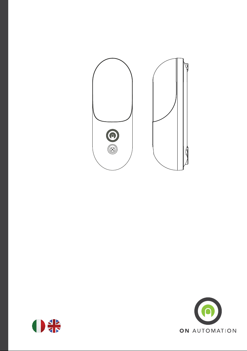
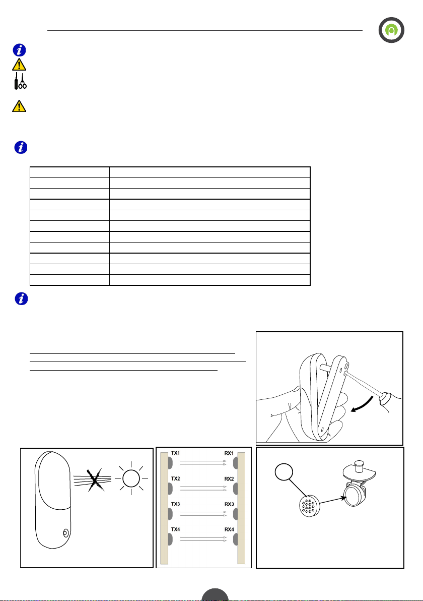
3- INSTALLAZIONE: impostare i dip e jumper prima di dare alimenta-
zione alle fotocellule, nel caso si presenti la necessità di modicare il settaggio,
togliere l’alimentazione, eseguire le modiche e ripristinare l’alimentazione.
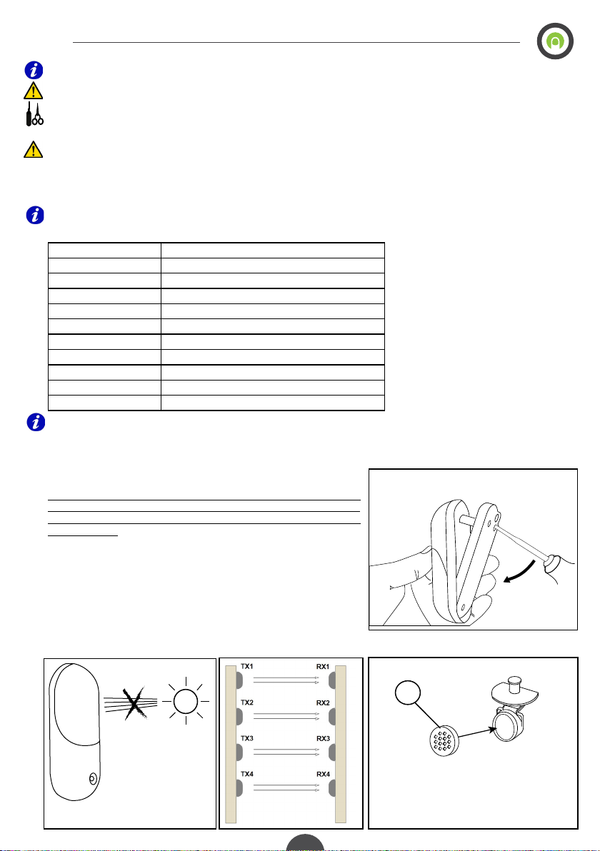
Per togliere il coperchio prima dell’ installazione, fare leggermente leva con un
cacciavite attraverso uno dei due fori di ssaggio inferiori dietro la base della
fotocellula, come mostrato in gura 1.
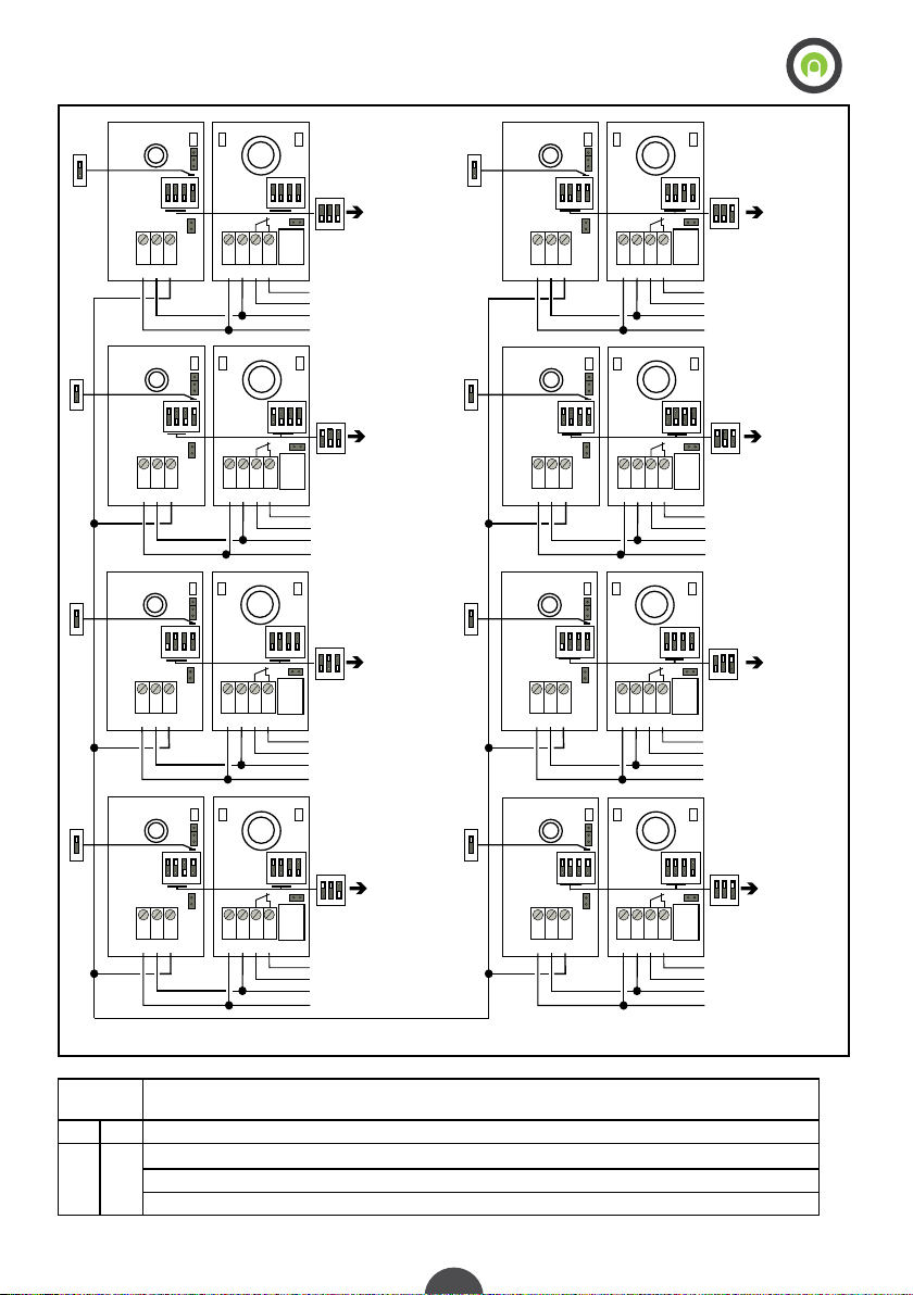
E’ consigliabile evitare di installare il ricevitore rivolto in direzione del sorgere
del sole (vedi gura 2), il ricevitore della fotocellula viene fornito con un ltro
S inserito sopra la lente, nel caso sia necessario aumentare la portata togliere il
ltro (gura 3-1).
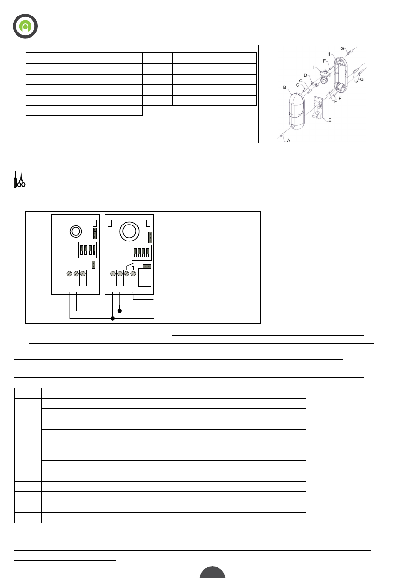
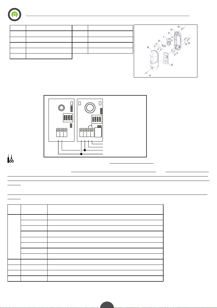
Per i collegamenti usare cavo con conduttori di sezione compresa tra 0,25 mmq
e 0,50 mmq. Installare le fotocellule su superci piane nella posizione prevista
dalle normative vigenti, avendo cura di allinearle una di fronte all’altra alla stes-
sa altezza. Per regolare la rotazione è suciente allentare le due viti C e ruotare
il supporto scheda I (vedi gura 3).
Una volta installata la fotocellula, per togliere il coperchio è suciente svitare
la vite A (vedi gura 4) ed estrarre dal basso verso l’alto il coperchio B con un
movimento diagonale .
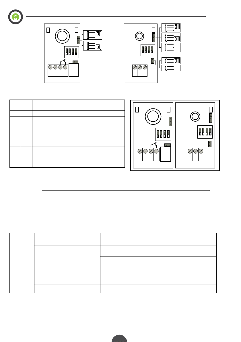
NO
RX
FIGURA 3
LIBRETTO ISTRUZIONI - INSTRUCTION MANUAL
FIGURA 1
FIGURA 2
S
FIGURA 3-1

3
LIBRETTO ISTRUZIONI - INSTRUCTION MANUAL
4- ASSIEME FOTOCELLULA:
Numero Descrizione
A Vite coperchio
B Coperchio
CViti ssaggio blocco rotazione
D Blocco rotazione
E Circuito stampato
5- DESCRIZIONE: la fotocellula FT180 può funzionare senza sincronismo (tutti i ricevitori possono leggere il raggio infrarosso
di tutti i trasmettitori) o con sincronismo digitale (ogni ricevitore leggere solo il raggio infrarosso emesso dal trasmettitore con lo
stesso indirizzo impostato tramite i dip switch).
6- CABLAGGIO: In gura 5 viene ragura il collegamento elettrico per il funzionamento senza sincronismo digitale (por-
tare il dip switch numero 4 di tutti i trasmettitori in posizione OFF e dare un indirizzo diverso per ogni coppia di fotocellule, tramite i
dip 1-2 e 3 presenti sia sul trasmettitore che sul ricevitore).
In gura 6 viene ragurato il collegamento elettrico per il funzionamento con sincronismo digitale no a un massimo di 8 coppie.
N.B.: con il funzionamento sincronismo digitale e una alimentazione in corrente alternata, tutti i morsetti numero 1 (+) della morset-
tiera M1 devono essere connessi allo stesso polo di alimentazione e tutti i morsetti numero 2 (-) sempre della morsettiera M1 vanno
connessi all’altro polo della alimentazione alternata, altrimenti il corretto funzionamento delle fotocellule non è garantito.
7- LEGENDA DIP SWITCH E JUMPER: Prima di dare alimentazione settare i dip switch e i jumper seguendo da tabella:
Dip RX Posizione Descrizione
1-2-3
OFF- OFF-OFF Indirizzo per sincronismo FOTOCELLULA 1 (MASTER)
ON-OFF-OFF Indirizzo per sincronismo FOTOCELLULA 2
OFF-ON-OFF Indirizzo per sincronismo FOTOCELLULA 3
ON- ON-OFF Indirizzo per sincronismo FOTOCELLULA 4
OFF-OFF-ON Indirizzo per sincronismo FOTOCELLULA 5
ON-OFF-ON Indirizzo per sincronismo FOTOCELLULA 6
OFF-ON-ON Indirizzo per sincronismo FOTOCELLULA 7
ON-ON-ON Indirizzo per sincronismo FOTOCELLULA 8
4-RX OFF Intervento immediato
4-RX ON Intervento ritardato per eliminare falsi allarmi causati da neve o forti piogge*
4-TX OFF Sincronismo non attivo
4-TX ON Sincronismo attivo
Togliere alimentazione, portare i dip switch nella posizione voluta e dare alimentazione , i dip switch vengono
letti alla accensione del sistema.
FIGURA 5
FIGURA 4
Numero Descrizione
F Vite ssaggio a parete
G Tasselli per ssaggio a muro
HFondo
ISupporto scheda
12/24VDC-AC
+
_
OUTPUT CONTACT
ON
1 2 3 4
DIP
JAP
M1
1 2 3 4
+ - cont.
ON
1 2 3
DIP
JAP
M1
1 2 3
+ - sync
1
2
3
JP1
DL1 DL2
DL2 RX
TX
JP1
4

Jumper
TX RX
Descrizione
JPA JPA Selezione tensione di alimentazione (chiuso 12VDC-AC, aperto 24VDC-AC)
JP1 - 1-2 potenza massima (portata massima)
2-3 potenza media (portata media)
Senza jumper potenza minima (portata minima)
Prima di dare alimentazione controllare la posizione dei jumper come riportato in tabella e gura 7:
FIGURA 6
LIBRETTO ISTRUZIONI - INSTRUCTION MANUAL
ON
1 2 3 4
DIP
JAP
M1
1 2 3 4
+ - cont.
ON
1 2 3
DIP
JAP
M1
1 2 3
+ - sync
12/24VDC-AC
+
_
OUTPUT CONTACT 1
ON
1 2 3 4
DIP
JAP
M1
1 2 3 4
+ - cont.
DIP
JAP
M1
1 2 3
+ - sync
12/24VDC-AC
+
_
OUTPUT CONTACT 2
ON
1 2 3 4
DIP
JAP
M1
1 2 3 4
+ - cont.
DIP
JAP
M1
1 2 3
+ - sync
12/24VDC-AC
+
_
OUTPUT CONTACT 3
ON
1 2 3 4
DIP
JAP
M1
1 2 3 4
+ - cont.
DIP
JAP
M1
1 2 3
+ - sync
12/24VDC-AC
+
_
OUTPUT CONTACT 4
TX1
TX2
TX3
TX4
RX1
RX2
RX3
RX4
ON
1 2
MASTER
4
ON
4
ON
4
ON
4
ON
PHOT.2
PHOT.3
PHOT.4
PHOT.1
SYNC.
ON
4
ON
1 2 3 4
ON
1 2 3 4
ON
1 2 3 4
ON
1 2 3 4
DIP
JAP
M1
1 2 3 4
+ - cont.
ON
1 2 3
DIP
JAP
M1
1 2 3
+ - sync
12/24VDC-AC
+
_
OUTPUT CONTACT 5
ON
1 2 3 4
DIP
JAP
M1
1 2 3 4
+ - cont.
DIP
JAP
M1
1 2 3
+ - sync
12/24VDC-AC
+
_
OUTPUT CONTACT 6
ON
1 2 3 4
DIP
JAP
M1
1 2 3 4
+ - cont.
DIP
JAP
M1
1 2 3
+ - sync
12/24VDC-AC
+
_
OUTPUT CONTACT 7
ON
1 2 3 4
DIP
JAP
M1
1 2 3 4
+ - cont.
DIP
JAP
M1
1 2 3
+ - sync
12/24VDC-AC
+
_
OUTPUT CONTACT 8
TX5
TX6
TX7
TX8
RX5
RX6
RX7
RX8
4
ON
4
ON
4
ON
4
ON
PHOT.6
PHOT.7
PHOT.8
PHOT.5
SYNC.
ON
4
ON
1 2 3 4
ON
1 2 3 4
ON
1 2 3 4
SYNC
3
ON
1 2 3
ON
1 2 3
ON
1 2 3
ON
1 2 3
ON
1 2 3
ON
1 2 3
ON
1 2 3
4

LIBRETTO ISTRUZIONI - INSTRUCTION MANUAL
8- LED DIAGNOSTICA: dopo aver controllato i cablaggio, i settagi dei dipswitch e dei jumper, dare alimentazione, controllare
lo stato dei led presenti nel trasmettitore e nel ricevitore come riportato il tabella e in gura 8:
LED
TX RX
Descrizione
DL2 Lampeggia il funzionamento normale.
- DL1 Lampeggia ad indicare la qualità dell’allineamento:
da 1 a 5 lampeggi, dove 5 lampeggi indicano l’allinea-
mento ottimale e 1 lampeggio indica un allineamento
insuciente (cercare di ottenere il numero massimo
di lampeggi). Un lampeggio prolungato indica l’entrata
nella modalità di funzionamento FILTRO NEVE.
- DL2 Visualizza lo stato del contatto in uscita, acceso con il
contatto chiuso. Con dip switch 4 in OFF il led si accen-
de con fotocellula non impegnata. Con dip switch 4 in
ON si accende con la fotocellula impegnata.
9- FUNZIONAMENTO CON SINCRONISMO DIGITALE è necessario rispettare il collegamento riportato in gura
6 (collegare assieme tutti i morsetti 3 dei trasmettitori), portare il dip switch numero 4 di tutti i trasmettitori in posizione ON
(abilitazione sincronismo), impostare i dip switch dell’indirizzo per sincronismo diverso per ogni coppia di fotocellule, tramite
i dipswitch 1 2 e 3 , almeno una coppia deve essere impostata come FOTOCELLULA 1 MASTER per sincronizzare il sistema.
Nel caso le fotocellule vengano alimentate in corrente alternata tutti i morsetti numero 1 (+) della morsettiera M1 devono essere
connessi allo stesso polo di alimentazione e tutti i morsetti numero 2 (-) della stessa morsettiera vanno connessi all’altro polo di
alimentazione.
10- CONTROLLO E ALLINEAMENTO: tramite il led DL1 è possibile controllare l’allineamento di ogni coppia di foto-
cellule, per aumentare la portata e creare un allineamento ottimale (5 lampeggi del led DL1) allentare le viti C riportate in gura
4, ruotare leggermente il circuito stampato no a ottenere il numero massimo possibile di lampeggi del led DL1 e serrare le viti.
Questa operazione deve essere eseguita per ogni singola coppia.
11- PROBLEMI E SOLUZIONI:
Problema Causa Soluzione
La fotocel-
lula non
funziona
Alimentazione errata Controllare la polarità e il settaggio dei jumper JAP
Settaggio sincronismo errato Manca la coppia di fotocellule congurata come Master (dip 1-2 e 3
in OFF)
Portare i dip switch 4 di tutti i trasmettitori in posizione ON
Ogni coppia deve avere i dip switch di indirizzo per sincronismo
uguale
A volte la fo-
tocellula non
funziona
Fotocellula non allineata Allineare la fotocellula controllando il numero di lampeggi del led
DL1
Altre fotocellule presenti nell’impianto Utilizzare solo fotocellule dello stesso tipo
12- DICHIARAZIONE CE CONFORMITÀ
Il costruttore On Automation dichiara che: FT180 – FOTOCELLULE INFRAROSSO DI-
GITALI 180° è conforme alle seguenti disposizioni pertinenti: 89/336/CEE, 93/68/CEE
5
ON
1 2 3 4
DIP
JAP
M1
1 2 3 4
+ - cont.
ON
1 2 3
DIP
JAP
M1
1 2 3
+ - sync
1
2
3
1
2
3
1
2
3
MAX RANGE
AVERAGE
MIN RANGE
12VDC-AC
24VDC-AC
1
2
3
JP1
DL1 DL2 DL2
4
1
2
3
1
2
3
NORMALY
OPEN
NORMALY
CLOSE
1
2
3
JP1
ON
1 2 3 4
DIP
JAP
M1
1 2 3 4
+ - cont.
ON
1 2 3
DIP
JAP
M1
1 2 3
+ - sync
1
2
3
JP1
DL1 DL2 DL2
RX TX
JP1
4

LIBRETTO ISTRUZIONI - INSTRUCTION MANUAL
NO
RX
FIGURE 3
6
FIGURE 1
FIGURE 2
2- TECHNICAL DATA: before installing the product, check that the area of installation is compatible with the temper-
ature limits.
Description Value
Power supply 12V/24V selectable with JPA
Power supply range 12-32 Vdc - 12-30 Vac
Relay contact capacity 1A - 30Vdc/Vac
Maximum capacity 25m (reduced in relation to environmental conditions)
Max consumption TX 30mA
Max consumption RX 40mA
Response time 40ms (normal) – 300ms (snow lter function)
Operating temperature between -20 and +70°C
Degree of protection IP 54 (EN60529)
Dimensions L x H x W 113mm x 40mm x 36mm
3- INSTALLATION: set the dipswitches and jumpers before powering
the photocells; always turn o the power before making adjustments and do
not turn it on again until aerwards.
To remove the cover before installation, use a screwdriver to gently lever it
up at the point of one of the lower xing holes behind the base of the photo-
cell, as shown in gure 1.
It is advisable to not install the receiver directly facing the rising sun (see
gure 2); the photocells receiver is sold with a lter S on the lens. In case you
want to improve the photocells range, remove the lter S (pic. 3-1).
Make the connections using cables measuring between 0.25 and 0.50 mm2.
Install the photocells on at surfaces in the position required by the regula-
tions in force, making sure to align them one in front of another at the same
height. To adjust the angle, simply loosen the two screws C and turn the
support board I (see gure 3).
In order to remove the cover aer the photocell is installed, simply undo
screw A (see gure 4) and pull the cover B upwards moving it diagonally.
is symbol draws attention to information to be read with care
is symbol draws attention to information concerning safety
is symbol draws attention to information concerning the wiring
1- WARNINGS: the FT180 wall-mounted 180° rotating photocells are suitable for installation on the automation devices
of gates or doors. ey can be used as a Type D device in accordance with standard EN12453 if connected to a control unit
with safety device control feature, or if checked every six months as part of the system maintenance schedule. e coded
synchronism allows all the transmitters to be mounted on the same side (up to a maximum of four). is avoids the risk of
reection associated with the cross-wise pattern of conventional photocells.
Key of the symbols in this manual:
S
FIGURA 3-1
LIBRETTO ISTRUZIONI - INSTRUCTION MANUAL

LIBRETTO ISTRUZIONI - INSTRUCTION MANUAL
FIGURA 5
FIGURE 4
7
4- PHOTOCELL ASSEMBLY:
Number Description
A Cover screw
BCover
C Rotation unit xing screws
D Rotation unit
E Printed circuit
5- DESCRIPTION: the FT180 photocell can work either without a synchronism (all the receivers can read the infra-red ray of all
transmitters) or with a digital synchronism (each receiver reads only the infra-red ray emitted by the transmitter with the same address set
with the dipswitches).
6- CABLING: Figure 5 shows the electrical connection for use without a digital synchronism (turn OFF dipswitch number 3 of all
the transmitters and set a dierent address for each pair of photocells using dipswitches 1 -2 and 3 on both the transmitter and the receiver).
Figure 6 shows the electrical connection for use with a digital synchronism up to a maximum of 8 pairs. N.B.: for use with a digital synchro-
nism and AC power supply, all the number 1 (+) terminals of terminal block M1 must be connected to the same pole, and all the number 2
(-) terminals also of terminal block M1 must be connected to the other pole of the AC power supply, otherwise the photocells may not work
correctly.
7- KEY OF THE DIPSWITCHES AND JUMPERS: Before turning on the power, set the dipswitches and jumpers as indicated in
the table:
Dip
RX
Position Description
1-2-3
OFF- OFF-OFF Address for synchronism PHOTOCELL 1 (MASTER)
ON- OFF-OFF Address for synchronism PHOTOCELL 2
OFF- ON-OFF Address for synchronism PHOTOCELL 3
ON- ON-OFF Address for synchronism PHOTOCELL 4
OFF-OFF-ON Address for synchronism PHOTOCELL 5
ON-OFF-ON Address for synchronism PHOTOCELL 6
OFF-ON-ON Address for synchronism PHOTOCELL 7
ON-ON-ON Address for synchronism PHOTOCELL 8
4-TX OFF Operation without synchronism (only for single pair)
4-TX ON Enables operation with the synchronism
4-RX OFF Immediate activation
4-RX ON Delayed activation to eliminate false alarms caused by snow or heavy rain*t
Number Description
F Wall xing screw
G Wall xing dowels
HBase
IBoard support
12/24VDC-AC
+
_
OUTPUT CONTACT
ON
1 2 3 4
DIP
JAP
M1
1 2 3 4
+ - cont.
ON
1 2 3
DIP
JAP
M1
1 2 3
+ - sync
1
2
3
JP1
DL1 DL2
DL2 RX
TX
JP1
4

LIBRETTO ISTRUZIONI - INSTRUCTION MANUAL
ON
1 2 3 4
DIP
JAP
M1
1 2 3 4
+ - cont.
ON
1 2 3
DIP
JAP
M1
1 2 3
+ - sync
12/24VDC-AC
+
_
OUTPUT CONTACT 1
ON
1 2 3 4
DIP
JAP
M1
1 2 3 4
+ - cont.
DIP
JAP
M1
1 2 3
+ - sync
12/24VDC-AC
+
_
OUTPUT CONTACT 2
ON
1 2 3 4
DIP
JAP
M1
1 2 3 4
+ - cont.
DIP
JAP
M1
1 2 3
+ - sync
12/24VDC-AC
+
_
OUTPUT CONTACT 3
ON
1 2 3 4
DIP
JAP
M1
1 2 3 4
+ - cont.
DIP
JAP
M1
1 2 3
+ - sync
12/24VDC-AC
+
_
OUTPUT CONTACT 4
TX1
TX2
TX3
TX4
RX1
RX2
RX3
RX4
ON
1 2
MASTER
4
ON
4
ON
4
ON
4
ON
PHOT.2
PHOT.3
PHOT.4
PHOT.1
SYNC.
ON
4
ON
1 2 3 4
ON
1 2 3 4
ON
1 2 3 4
ON
1 2 3 4
DIP
JAP
M1
1 2 3 4
+ - cont.
ON
1 2 3
DIP
JAP
M1
1 2 3
+ - sync
12/24VDC-AC
+
_
OUTPUT CONTACT 5
ON
1 2 3 4
DIP
JAP
M1
1 2 3 4
+ - cont.
DIP
JAP
M1
1 2 3
+ - sync
12/24VDC-AC
+
_
OUTPUT CONTACT 6
ON
1 2 3 4
DIP
JAP
M1
1 2 3 4
+ - cont.
DIP
JAP
M1
1 2 3
+ - sync
12/24VDC-AC
+
_
OUTPUT CONTACT 7
ON
1 2 3 4
DIP
JAP
M1
1 2 3 4
+ - cont.
DIP
JAP
M1
1 2 3
+ - sync
12/24VDC-AC
+
_
OUTPUT CONTACT 8
TX5
TX6
TX7
TX8
RX5
RX6
RX7
RX8
4
ON
4
ON
4
ON
4
ON
PHOT.6
PHOT.7
PHOT.8
PHOT.5
SYNC.
ON
4
ON
1 2 3 4
ON
1 2 3 4
ON
1 2 3 4
SYNC
3
ON
1 2 3
ON
1 2 3
ON
1 2 3
ON
1 2 3
ON
1 2 3
ON
1 2 3
ON
1 2 3
Jumper
TX RX
Description
JPA JPA Selection of voltage supply (closed 12VDC-AC, open 24VDC-AC)
JP1 -1-2 maximum power (maximum capacity)
2-3 medium power (medium capacity)
Without jumpers minimum power (minimum capacity)
Before turning on the power, check the position of the jumpers as shown in the table and gure 7:
FIGURE 6
8

LIBRETTO ISTRUZIONI - INSTRUCTION MANUAL
9
8- DIAGNOSTICS LED: aer checking the cabling and the settings of the dipswitches and the jumpers, turn on the power and check
the LEDs on the transmitter and receiver with reference to the table and gure 8:
LED
TX RX
Description
DL2 Flashes to indicate normal operation
- DL1 Flashes to indicate the quality of alignment: between 1
and 5 ahses, where 5 ashes indicate perfect align-
ment and 1 ash indicates insucient alignment (try to
obtain the maximum number of ashes). A long ash
indicates that the SNOW FILTER function is enabled.
- DL2 Indicates the status of the output contact, activated
with the contact closed. When dipswitch 4 is OFF,
the LED is activated with the photocell not engaged.
When dipswitch 4 is ON, the LED is activated with the
photocell engaged.
9- OPERATION WITH DIGITAL SYNCHRONISM make the connections as shown in gure 6 (connect together all
the number 3 terminals of the transmitters), turn ON the number 4 dipswitches of all the transmitters (to enable the synchronism),
and set the dipswitches of the dierent synchronism address for each pair of photocells, using dipswitches 1-2 and 3; a minimum
of one pair must be set at PHOTOCELL 1 MASTER for synchronising the system. If the photocells are to be powered at alternating
current, all the number 1 (+) terminals of terminal block M1 must be connected to the same pole and all the number 2 (-) termi-
nals of the same terminal block must be connected to the other pole.
10- CONTROL AND ALIGNMENT: LED DL1 serves to check alignment of each pair of photocells; to increase capacity
and set optimal alignment (5 ashes of LED DL1), loosen screws C as shown in gure 4, turn the printed circuit board slowly and
gently until LED DL1 ashes the full number of times, and then tighten the screws. Repeat this procedure for each pair.
11- TROUBLESHOOTING:
Problem Cause Solution
e photo-
cell does not
work
Incorrect power supply Check the poles and setting of the JAP jumper
Incorrect setting of the synchronism No pair of photocells is congured as the Master (dip 1-2 and 3 OFF)
Turn ON the number 4 dipswitches of all the transmitters
e dipswitches of each pair must be associated with the same syn-
chronism address
e photo-
cell does not
always work
Photocell not aligned Align the photocell, checking the number of ashes of LED DL1
Other photocells on the system Use only photocells of the same type
12- CE DECLARATION OF CONFORMITY
e manufacturer On Automation declares that: FT180 – 180° DIGITAL INFRA-RED
PHOTOCELLS conforms to the following applicable standards: 89/336/EEC, 93/68/EEC
ON
1 2 3 4
DIP
JAP
M1
1 2 3 4
+ - cont.
ON
1 2 3
DIP
JAP
M1
1 2 3
+ - sync
1
2
3
1
2
3
1
2
3
MAX RANGE
AVERAGE
MIN RANGE
12VDC-AC
24VDC-AC
1
2
3
JP1
DL1 DL2 DL2
4
1
2
3
1
2
3
NORMALY
OPEN
NORMALY
CLOSE
1
2
3
JP1
ON
1 2 3 4
DIP
JAP
M1
1 2 3 4
+ - cont.
ON
1 2 3
DIP
JAP
M1
1 2 3
+ - sync
1
2
3
JP1
DL1 DL2 DL2
RX TX
JP1
4

10

11

C
O
M
P
L
I
E
S
W
I
T
H
ISFT180-8 ver. 1.0 2017-06-21
Via Antonio Ferrero, 9 - Padova 35133 - Italy
Tel: +39 049 8876545
E-mail: info@onautomation.com - www.onautomation.com
Table of contents
Languages:
Popular Accessories manuals by other brands

Festo
Festo MPS 8034566 quick start guide

Benchmark Scientific
Benchmark Scientific Incu-Shaker Mini Operation manual

Design
Design SCENTED INTERIORS ARC 2 User manual installation

MKS
MKS HPS 937A Series Owner's operation and maintenance manual

Baumer
Baumer UNAM 12N3912/S14 manual

TREVIDEA
TREVIDEA Girmi CT10 user manual

ROSE DISPLAYS
ROSE DISPLAYS SPIDER RING WITH CABLE AND SAUCER manual

CommScope
CommScope AMP NETCONNECT 553947 Series instruction sheet

Cantatis Ultimate Audio
Cantatis Ultimate Audio Overture 192 user guide

optris
optris CSmicro Operator's manual

Lightolier
Lightolier Lytespan 22OR6 specification

Waters Industries
Waters Industries SUNCATCHER SW-9374 manual