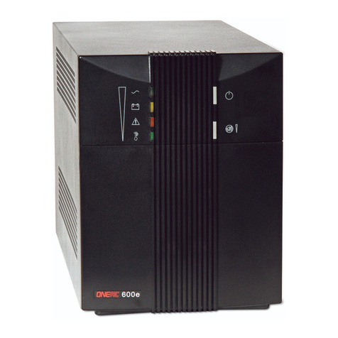
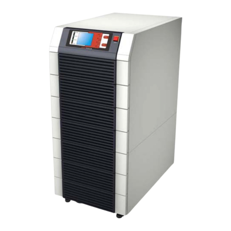
ONEAC S07KXAU User manual

ONEAC Sinergy®S II Series
Uninterruptible Power Supply
Operating Manual
•S07KXAU
•S1K0XAU
•S2K5XAU
•SBP1K5-2
•SBP3K0-2
•S2K0XAU
•S3K0XAU
•S2K0XHU
•S3K0XHU

Sinergy
®
S II Series User Instruction Manual
IMPORTANT SAFETY INSTRUCTIONS
SAVE THESE INSTRUCTIONS.
Please read and save these instructions. This manual contains important instructions for ONEAC models:
Follow these instructions during installation and maintenance of the UPS and batteries.
If you have a problem with the UPS, please refer to this manual before calling the Technical Support
Department. The Troubleshooting section on page 29 addresses most UPS-related issues.
Licenses andTrademarks
ONEAC, Sinergy , MananageUPS and MopUPS are all registered trademarks of ONEAC Corporation. All
other trademarks, product and corporate names are the property of their respective owners.
913-602 @ Rev. A
7/06
• S0K7XAU
• S1K0XAU
• S2K5XAU
• SBP1K5-2
• SBP3K0-2
• S2K0XAU
• S3K0XAU
• S2K0XHU
• S3K0XHU
ONEAC USA
27944 North Bradley Road
Libertyville, IL 60048-9700
USA
Telephone: (847) 816-6000
Toll Free: (800) 327-8801
Facsimile: (847) 680-5124
ONEAC EUROPE
George Curl Way
Southampton, Hampshire SO18 2RY
United Kingdom
Telephone: +44 (0) 2380 610311
Facsimile: +44 (0) 2380 610852


Sinergy S II Series Series UPS User Instruction Manual i
Sinergy® S II Series User Instruction Manual ......................................................................................................................i
Introduction .....................................................................................................................................................................1
Registering Your ONEAC UPS ...........................................................................................................................................1
Technical Support .............................................................................................................................................................1
FCC Compliance ..............................................................................................................................................................1
Safety Compliance ...........................................................................................................................................................1
About This Manual ....................................................................................................................................................1
Symbols .....................................................................................................................................................................2
Safety ...............................................................................................................................................................................3
Intended Use .............................................................................................................................................................3
General Warnings ......................................................................................................................................................3
Safety Notices ............................................................................................................................................................3
Battery Safety ............................................................................................................................................................4
Repacking of Unit ......................................................................................................................................................4
Setup ...............................................................................................................................................................................5
Delivery ......................................................................................................................................................................5
Unpacking .................................................................................................................................................................5
Storage ......................................................................................................................................................................6
Environmental Conditions ..........................................................................................................................................6
Floor Loading .............................................................................................................................................................6
Ventilation .................................................................................................................................................................6
Installation .......................................................................................................................................................................6
Rack-Mounting the UPS or External Battery Cabinets .................................................................................................7
Tower (Floor) Mounting and External Battery Cabinets ...............................................................................................8
Electrical preparations ................................................................................................................................................9
Connections ..............................................................................................................................................................9
Theory of Operation .......................................................................................................................................................10
UPS Mode ................................................................................................................................................................10
Battery Mode ...........................................................................................................................................................10
Bypass Mode ...........................................................................................................................................................11
Front Panel Display and Control ...............................................................................................................................11
System Indicators .....................................................................................................................................................12
Rear Panel ................................................................................................................................................................13
UPS Start-up & Shutdown ..............................................................................................................................................15
Normal UPS Start-up Procedure ................................................................................................................................15
Manual Bypass Procedure ........................................................................................................................................15
UPS Shutdown Procedure ........................................................................................................................................15
Remote Power Off (RPO) ..........................................................................................................................................15
Maintenance ..................................................................................................................................................................16
UPS Storage .............................................................................................................................................................16
Battery Testing .........................................................................................................................................................16
Replacing Batteries ...................................................................................................................................................16
Battery Disposal .......................................................................................................................................................18
Interfaces .......................................................................................................................................................................18
Serial interface COM 3 .............................................................................................................................................18
Interface Slot COM ..................................................................................................................................................18
Communications ......................................................................................................................................................18
Optional Isolated Contacts Card ...............................................................................................................................19
Troubleshooting .............................................................................................................................................................21
Warranty ........................................................................................................................................................................22
Batteries ..................................................................................................................................................................22
Limitations of Warranty ............................................................................................................................................22
Exclusive Remedies ...................................................................................................................................................22
Return Procedure .....................................................................................................................................................22
Appendix A: Features and Specifications .........................................................................................................................23


ii Sinergy S II Series User Instruction Manual
Physical and Electrical Specifications ........................................................................................................................ 24
Specifications .......................................................................................................................................................... 25

Introduction
Sinergy S II Series Series UPS User Instruction Manual 1
Introduction
Thank you for selecting this uninterruptible power supply (UPS). ONEAC’s Sinergy S II Series UPS
offers the most reliable protection from the harmful effects of electrical line disturbances for your
computing and communications equipment. ONEAC’s ISO 9001 certification represents our commitment
to building world-class products. We take pride in every unit that leaves our manufacturing facility.
RegisteringYour
ONEAC UPS
To ensure that your Sinergy S II Series UPS model and serial number are registered, complete and mail
the enclosed postage-paid warranty card or go on line at www.oneac.com.
Technical Support
ONEAC offers 24-hour technical support. To contact ONEAC Technical Services:
• North America: (847) 816-6000, option 3
or toll free (800) 327-8801, option 3.
• Europe: +44 (0) 1235 861962
Please check with ONEAC Technical Services before attempting to repair or return any ONEAC product.
If an ONEAC UPS needs repair or replacement, ONEAC Technical Services will issue a Return Material
Authorization (RMA) number along with instructions on how to return the UPS.
FCC Compliance
ATTENTION:
Changes or modifications to this unit not expressly approved by the party responsible or
in FCC compliance could void the user’s authority to operate the equipment.
The 2-3 kVA models have been tested and comply with the limits for a ClassA digital device, pursuant to
Part 15 of FCC Rules. These limits are designed to provide reasonable protection against harmful
interference when the UPS is operating in a commercial environment. The UPS generates, uses, and can
radiate radio frequency energy. If installation and use is not in accordance with the instruction manual, it
may cause harmful interference to radio communications.
ATTENTION:
Operation of this equipment in a residential area may cause harmful radio
communications interference. The user is responsible for correcting the interference.
The 700VA to 1500 VA models have been tested and comply with the limits for a Class B digital device,
pursuant to Part 15 of FCC Rules. These limits are designed to provide reasonable protection against
harmful interference when the UPS is operating in a residential environment. The UPS generates, uses,
and can radiate radio frequency energy. If installation and use is not in accordance with the instruction
manual, it may cause harmful interference to radio communications.
Safety Compliance
UL/cUL listing to UL1778
TUV compliance to EN62040-1
CE
AboutThis Manual
This manual contains information regarding the installation, operation and use of the Uninterruptible
Power Supply (UPS).
Consult this manual before installation of the equipment, which should be performed only by qualified
personnel. This User’s Manual should be kept for later reference for operation and maintenance of the
UPS.
These instructions may be supplemented with additional sheets, describing specific extensions or options.

2
Sinergy S II Series Series UPS User Instruction Manual
Symbols
The following symbols are used in this manual:
ATTENTION:
Indicates instructions, which if not observed, may endanger reliability of your UPS or the
security of your data.
WARNING:
Indicates instructions, which if not observed, present risk of electric shock, may endanger
your life, your health, reliability of your UPS or the security of your data.

Safety
Sinergy S II Series Series UPS User Instruction Manual 3
Safety
• This device serves as an uninterruptible power supply for connected loads. The device is in
compliance with all relevant safety regulations concerning information technology equipment, for
use in an office environment.
• Depending on the type and rating of UPS device, certain configurations of battery extensions may
be connected. These battery extensions may only be connected to the compatible basic UPS unit.
GeneralWarnings
WARNING:
We consider the safety of personnel to be of paramount importance. For this reason it is
essential that procedures relating to safety in this manual be carefully reviewed before commencing work,
and properly adhered to thereafter. The User or Operator may intervene in the operation of the UPS
provided that the instructions laid out in the section titled “Installation” on page 6 are strictly followed.
WARNING: Even when all switches and/or circuit breakers are open, dangerous voltages are present
within this unit!
There are no user-serviceable parts inside. Only factory authorized technical personnel
may carry out any operation that requires protection panels to be opened and/or removed.Any repairs or
modifications by the user may result in out-of-warranty repair charges, unsafe electrical conditions, or
violation of electrical codes.
Safety Notices
WARNING:
Read the following safety notices carefully! Disregard of these safety notes may endanger
your life, your health, and the reliability of your device and the security of your data.
• Transport the unit only in suitable packaging (protected against jolts and shocks).
• If the equipment is moved from a cold environment to a warmer operating location, condensation
may occur. Before you switch on the equipment it must be absolutely dry.An acclimatization period
of at least two hours is required.
• The equipment must be installed in accordance with the environmental conditions specified in
“Environmental Conditions” and in Table 2.
• Even with all buttons in “OFF” position the device (UPS) is not isolated from the mains. To isolate
completely from the mains, the power cord must be disconnected.
• This equipment services power from more than one source. The output terminals and/or receptacles
may have voltage present even when the unit is unplugged. UPS’s present a different safety issue
than most electrical equipment because unplugging the UPS puts it into backup mode. Unplugging
the UPS does not remove the electrical charge.
• In case of interruption of the mains voltage, the integrated battery maintains the power supply to the
user’s equipment.
• The power supply cord is intended to serve as the disconnection device. The outlet-socket must be
near the equipment and must be easily accessible.
• This UPS must be connected to an earthed mains outlet-socket.
• Place all cords so that nobody can stand on them or trip over them. When connecting the device to
the power supply, follow the instructions in the section titled “Installation”.
• Make sure that no objects (e.g. pins, necklaces, paper clips, etc.) get inside the device.
• In emergencies (e.g. damaged case, controls or power cables, penetration of liquids or foreign
matter) switch off the device and contact Technical Support for assistance.
• Do not connect equipment that will overload the UPS or demand DC-current.
• When cleaning the unit, follow the instructions in the section titled “Maintenance”.
• Data transmission lines should not be connected or disconnected during a thunderstorm.
• Remote Power Off (RPO) is located on the rear of the unit (seeFigure 11 and Figure 12).When this
connection is open, the logic circuit will immediately shut down the UPS output.
• When installing units in racks do not allow racks to become “top heavy.” Install heaviest equipment
(typically the UPS and batteries) near bottom of rack, and install this equipment before installing
equipment higher in the rack.
Intended Use

Safety
4
Sinergy S II Series Series UPS User Instruction Manual
Battery Safety
WARNING:
The batteries installed in the UPS and within the battery extensions contain electrolyte.
Under normal conditions the containers are dry. A damaged battery may leak electrolyte that can be
dangerous in contact with the skin and cause irritation to the eyes. Should this happen wash the affected
part with copious amounts of water and seek immediate medical advice.
• Voltage is always present on the battery terminals.
• Even when discharged, a battery has the capacity to supply a high short circuit current, which, in
addition to causing damage to the battery itself and to associated cables, may expose the operator to
the risk of burns.
• Batteries should not be kept in storage for periods exceeding 6 months at 25°C without being
recharged (having been charged to 100% at the beginning of any such period). If these conditions
are not respected the performance of the battery can no longer be guaranteed. It is advisable to
recharge the batteries at least once every 4 months.
• Since new batteries often do not provide full capacity after an initial charge it may be necessary to
carry out a number of discharge/recharge cycles before optimum performance is achieved.
• In order to protect the environment, batteries must be disposed of in accordance with the regulations
governing disposal/recycling of toxic and harmful waste.
Repacking of Unit
Do not pack the equipment until at least two (2) hours have elapsed since the last recharge.
Place the equipment in bags made of a material sufficiently porous to allow it to breathe (e.g. 100µm
polyethylene).
Do not remove air from the packaging.
When packing unit for movement by common carrier, place in original, or equivalent packaging container.

Setup
Sinergy S II Series Series UPS User Instruction Manual 5
Setup
The equipment has been thoroughly checked before shipment. Upon receipt, check the packaging and
ensure that the contents are undamaged.Any damage must be reported to the shipper and any missing
parts must be reported to the supplier immediately.
Unpacking
Care should be taken when removing the packaging in order to avoid damaging the equipment. Check all
packaging materials to ensure that no items are discarded. Remove the packaging following the sequence
illustrated in Figures 1.
WARNING:
This unit is heavy and requires two persons for safe lifting
Tools Required
• Scissors or Knife
• Screwdriver
Fig. 1: Unpacking the UPS
This UPS includes:
• (1) UPS
• (1) USB Cable
• Mounting Hardware
• Tower Stands
• MopUPS Professional
• Manual
Additional items:
For high voltage models (models with XHU in the part number) also include:
• Cord Retention Bracket
• (2) IEC320 to IEC Extension Cords
• (1) IEC/NEMA Input Power Cord
Delivery

Installation
6
Sinergy S II Series Series UPS User Instruction Manual
Storage
If the UPS is to be stored prior to use, it should be stored in a clean, dry environment and away from
temperature extremes. It is recommended that the equipment be stored in a temperature controlled,
moderate humidity environment. Table 1 below provides the temperature and humidity storage limits:
NOTE:
When storing equipment, every 8°C above 25°C reduces the shelf life of the battery by 50%. More
frequent battery charging is required to maintain the batteries in storage at these greater temperatures.
Environmental
Conditions
The UPS must be installed on a level and even surface and in an area protected from extremes of
temperature, water, humidity and the presence of conductive powder or dust (See Table 2 on page 6). Do
not stack units and do not place any objects on top of a unit.
The functional temperature range of the UPS is 32°F to 104°F (0°C to 40°C).
The ideal ambient temperature range is 60°F to 77°F (15 °C to 25°C).
Expected battery runtimes and battery life is based on operational temperatures between 68°F and 77°F (20°C
and 25°C). Operation of the equipment above 77°F (25°C) reduces the service life of the batteries dramatically.
Floor Loading
Taking into consideration the weight of the UPS, extension battery packs, and any other equipment that
may be mounted in an associated rack, confirm that the floor in the chosen location be capable of
supporting the weight of the combined units.
NOTE:
Weights for the UPS and battery packs are shown in Appendix A, “Specifications”.
Ventilation
It is necessary to leave a minimum space of at least two inches (50 mm) in front and rear of the UPS to
allow a flow of air.
Electrical maintenance and servicing requires access to the front and back of the UPS. Provide the
necessary space to allow service personnel access to the UPS.
Installation
ATTENTION:
This UPS is supplied with standard power cords and receptacles suitable for its use in
your area of operation. It may be installed and operated by non-technical personnel..
Table 1. Storage Data
Temperature limits -Batteries ONLY 32°F to 104°F (0°C to +40°C)
Temperature limits - UPS without batteries -13°F to 131°F (-25°C to +55°C)
Temperature limits – UPS with batteries 32°F to 104°F (0°C to +40°C)
Relative humidity (non-condensing) 0% to 90%
Table 2. Installation Data
Item Specification
Ambient temperature 32°F to 104°F (0 °C to 40C°)
Relative humidity (non condensing) 90%
Environment Controlled (i.e. Office or equivalent)
Max. altitude (w/o derating) 3300 ft. above sea level (1000 m.a.s.l.)
Derated to 82% 10000 ft. above sea level (3048 m.a.s.l.)
Input Power Connection Rear
Output Power Connection Rear
Battery Power Connection Rear
Air inlet Front
Air outlet Rear

Installation
Sinergy S II Series Series UPS User Instruction Manual 7
Rack-Mounting the
UPS or External
Battery Cabinets
TheUPSsandexternalbattery are designed to be rack-mounted in four-post frames.The UPS and external
battery cabinets use identical mounting hardware and the procedure for mounting either is the same.
NOTE:
The Rack-mount UPS draws cooling air from the front. If the rack has a door on the front, make
sure that there is some clearance between the vents and the rack door.
Because of the weight of these units, two people are recommended to lift and hold into position while all
fasteners are secured. Please use only the supplied fasteners to attach the supplied mounting brackets to
the UPS or external battery.
If external batteries are included in your installation, please mount them first and as low as possible. Start
with the lowest available position and work up.Your UPS should be installed last and end up on the top
of all the battery units for proper cable routing.
ATTENTION:
Use all supplied mounting hardware on each UPS and external battery. NEVER depend
on lower devices to support other devices.
All mounting materials are provided to install the UPS into a rack. To prepare the UPS and external
batteries for use in a rack configuration, first install the included mounting rails, then install the UPS and
batteries following the steps below.
1. Assemble side rails and secure each rail together with three screws.
2. Attach front of rails to front of rack with two screws provided.
3. Attach rear of rails to rear of rack with two screws provided.
4. Attach front brackets to each side of UPS with four screws on each side.
5. Slide UPS into position in the rack and secure with two screws on each side of UPS.
6. Repeat the above steps for each UPS or battery to be mounted.
Fig. 2: Mounting the UPS in a Rack
After mechanical installation is complete, follow the instructions in “Connections” on page 9. Connect
your UPS and external battery cabinets.

Installation
8
Sinergy S II Series Series UPS User Instruction Manual
Tower (Floor)
Mounting and
External Battery
Cabinets
The UPS and external battery are designed to be floor standing as an alternative to rack mounting.
ATTENTION:
Use all supplied mounting hardware on each UPS and external battery.
Please use only the supplied fasteners to attach the supplied mounting brackets to the UPS or external
battery. Each UPS and External Battery Cabinet requires four (4) screws provided.
After mechanical installation is complete follow the instructions in the section titled “Connections” on
page 9 to connect your UPS and external battery.
Mounting theTower UPS Only
1. Assemble the two sets of feet included with the UPS,
Fig. 3: Tower Feet
2. Place the UPS between feet as shown in Figure 4.
Fig. 4: UPS Tower Set Up
Mounting theTower UPS Plus One External Battery
1. Assemble the two sets of feet with the spacer provided as shown in Figure 5.
Fig. 5: UPS Feet with Spacer
2. Place feet under UPS and external battery, see Figure 6.
Fig. 6: UPS Tower with Battery Set Up
3. Secure UPS and battery with bracket and screws provided.

Installation
Sinergy S II Series Series UPS User Instruction Manual 9
Cord Retention Bracket (for models with IEC receptacles)
UPS models that utilize IEC inlets and receptacles have an included accessory that may be installed to
help secure the input and output cords in place.
To install the cord retention bracket:
1. Remove the four screws from the right side of the rear of the UPS
2. From the top, open cord retainer.
3. Reinstall screws in the rear of the UPS.
4. Secure each IEC cord using supplied tie wraps. Thread one end of tie wrap through the hole in the
cord retainer and around IEC cord. Secure to other end of the tie wrap.
Fig. 7: Cord Retention Bracket
Electrical
preparations
WARNING:
Before connecting any input wiring to the UPS, take precautions to insure that all circuits
being used are the proper voltage and current required for the UPS. If this UPS is not used with the
supplied power cord, care must be taken to use properly rated cords (see “Appendix A: Features and
Specifications” on page 23) which comply with all regional and local codes.
WARNING:
UPS output receptacles are energized when the front panel power switch is in the “ON”
position (green LED is illuminated).
WARNING:
Electrical shock hazard: Even when the UPS is disconnected from the mains, hazardous
voltages may still exist at the output receptacles of the UPS. The UPS receives power from more than one
source – AC input and DC input from batteries. All input sources (AC and DC) must, therefore, be
disconnected before carrying out maintenance work inside the UPS.
Connections
Battery Connections
WARNING:
Before connecting a battery pack to the UPS, the circuit breaker of the battery pack must be
switched to “OFF.” After electrical connection with the UPS is established, the breaker must be switched
to “ON.”
NOTE:
Each Battery Pack contains two battery connectors.The first battery pack is connected to the UPS
using the cable supplied with the pack. Each additional extension battery pack is connected by attaching
its cable to the previous pack
If additional battery cabinets are to be used, they should be connected prior to connecting the UPS to the
input power. To connect external battery cabinets, follow the steps below.
1. Set the circuit breaker on each battery cabinet to the “OFF” position.
2. Connect battery plug at the end of the cable attached to the battery cabinet closest to UPS to the
battery receptacle on the rear of the UPS.
3. Connect the battery plug at end of the cable from the next battery cabinet to the battery receptacle on
the battery cabinet plugged into UPS.
4. Continue “daisy-chaining” the batteries until all are connected.
Cord Retention Bracket

Theory of Operation
10
Sinergy S II Series Series UPS User Instruction Manual
5. Connect the battery counter cable between the UPS and the battery cabinet closest to UPS.
6. Set the circuit breakers on each battery cabinet to “ON” position.
Fig. 8: Battery Circuit Breaker
Power Connections
After all external batteries are connected, make the necessary input and output power connections by
following the steps below.
1. Connect the input power cord to the AC outlet
NOTE:
The batteries will immediately begin charging upon availability of input power.
2. Connect the load to the UPS.
It is suggested that the highest priority equipment be attached to the main outlets and that lower
priority loads be attached to the two programmable outlets.
NOTE:
With the use of MopUPS
®
software or the ManageUPS
®
network adaptor, the programmable
outlets can be set to have a delayed start-up or a pre-scheduled shut-down during battery operation in
order to conserve battery power for the highest priority loads.
3. If using a UPS with IEC receptacles and inlets, cords may be secured by using the cord retainer and
supplied tie wraps, see Figure 7.
4. After all connections are made, follow the instructions in the section titled “UPS Start-up &
Shutdown” on page 15 to start your UPS and external battery.
Theory of
Operation
ATTENTION:
This UPS is supplied with standard power cords and receptacles suitable for its use in
your area of operation. It may be installed and operated by non-technical personnel.
UPS Mode
In use, the UPS is connected betweenAC input power and the load. The operation of this UPS is based
on the on-line principle in which the inputAC power is first converted to DC, and secondarily converted
back to a sine wave of a fixed frequency and voltage to supply controlled power to the load. This UPS
topology is used to isolate the critical load (e.g. servers, switches, routers, etc.) from a variety of power
line problems, including the total loss of inputAC power.
Battery Mode
In the event of a mains failure, the maintenance-free batteries will continue to provide an uninterrupted
supply of energy to the load. In practice, most mains failures are of relatively short duration. Therefore,
the energy stored in the UPS’s batteries is, in most cases, sufficient to ensure continuous operation of the
connected systems until the mains power is reestablished. In the event of a long lasting mains failure, the
UPS can be utilized with shutdown software to enable a controlled shutdown of connected systems.
The most reliable method for determining the estimated battery runtime is the application of MopUPS
software or a ManageUPS network card. With this software, the estimated remaining battery capacity is
indicated before and during an AC power failure. These products also allow for automated shutdown
procedures that can shut down the attached devices after safely closing open application programs and the
operating system. After return of the mains voltage, the UPS automatically restores power to the
connected equipment.
Circuit Breaker

Theory of Operation
Sinergy S II Series Series UPS User Instruction Manual 11
Bypass Mode
In the event of a brief overload on the UPS or internal UPS failure, the load is immediately supplied directly
from the mains via an automatic internal bypass.As soon as normal status is reestablished, an automatic
switch over to inverter operation is performed.
• < 110% warning
• 110% - 130%: 12 seconds, switches to bypass
• >130% - 1.5 seconds, switches to bypass
Contact technical service for further details
Front Panel Display
and Control
The front panel display contains a series of switches and indicator LED’s that provide the operator with the
current status of the UPS, and the ability to change UPS operational mode.
• Main UPS ON/OFF switch
• A simplified block diagram of the UPS shows the current operational mode of the UPS (i.e. on-line,
on-battery, or on-bypass.)
• Two LED indicators show the current status (ON or OFF) of the controllable receptacle groups 1 and
2.
• Four additional LEDs provide error status, UPS load percentage or battery charge percentage
depending on if the associated front panel button is pressed.
Fig. 9: Front Panel Display
1. Site Wiring Fault LED 8. ON LED
2. Battery Fault LED 9.
Display Selector(Battery Charge/UPS Load% (on LED’s 1-4)
3. UPS Fault LED 10. LED Test/Alarm Reset
4. UPS Overload LED 11. Operation in BYPASS Mode
5. Controllable Receptacle Group 1 On / Off 12. Operation in ON-LINE Mode
6. Controllable Receptacle Group 2 On / Off 13. Output Supplied by Battery
7. Standby (ON / OFF Switch)
5
9
64
10
321
11
7
12 13
8

Theory of Operation
12
Sinergy S II Series Series UPS User Instruction Manual
System Indicators
Fig. 10: Block Diagram
Table 3. System Indicator
Condition Audible Visual
UPS Off/unplugged None None
UPS Off/plugged in None LEDs #1, #2, #3, #4 are on to show battery capacity.
Start-up On - AC Power One and two beeps After start-up checks, #12 turns on.
Start-up On - Battery One and five beeps After start-up checks, #13 turns on.
On-Line NA On-Line LED #12 is on.
On-Bypass NA On-Bypass LED #11 is on.
Transfer to Battery Three beeps On-Line LED #12 turns off;
On-Battery LED #11 turns on.
Low Battery Beep every 3 seconds #13 flashes every three seconds.
End of Battery Constant sound #13 is on constant
Overload < 110% Overload indicator #4 is on
UPS Fault > 110% Beeps every second UPS Fault indicator #11 is on

Theory of Operation
Sinergy S II Series Series UPS User Instruction Manual 13
Rear Panel
Fig. 11: Rear Panel for 700 VA, 1000 VA, 1500VA (120 Volt) Models
1. Environmental Reference Ground 8. Fan
2. Input Power Connections 9. Output Receptacles
3. Controllable Receptacles 10. Interface COM3 (RS232)
4. Slot Interface COM 11. USB Interface
5. RPO Connection 12. External Battery Power Receptacle
6. Battery Counter Connector 13. Site Wiring Fault Indicator
7. Push Button for Phase/Neutral Reversal Test
3
4
67
8
9
11
121310 512
9

Theory of Operation
14
Sinergy S II Series Series UPS User Instruction Manual
Fig. 12: Rear Panel for 2000 VA and 3000 VA
1. Environmental Reference Ground 9. Output Receptacles (9C full nameplate rated output)
2. Input Power Connections 10. Interface COM3
3. Controllable Receptacles 11. USB Interface
4. Slot Interface COM 12. External Battery Power Receptacle
5. RPO Connection 13. Site Wiring Fault Indicator
6. Battery Counter Connector 14. Circuit Breaker for 3 Only (3000VA, 120V only)
7. Push Button for Phase/Neutral Reversal Test 15. Circuit Breaker for 9 Only (3000VA, 120V only)
8. Fans 16. Circuit Breaker for 9A (3000VA, 230V only)
17. Circuit Breaker for 9B (3000VA, 230V only)
2000 VA (120 V) Model
3000 VA (120 V) Model
2000 VA (230 V) Model
3000 VA (230 V) Model
1
2
345
67889
9C
11
12
13
10
2
345
67889
9C
11
12
13
10
14 15
2
12 18854
9
11
3
13
10
67
2
12 18854
9A
11
3
13
10
67
14 16 17
9B 9C
1

UPS Start-up & Shutdown
Sinergy S II Series Series UPS User Instruction Manual 15
Fig. 13: Rear Panel External Battery Pack
1. Battery Power Receptacle (input from UPS) 3.BatteryPowerReceptacle(outputtoadditionalbattery)
2. Battery Circuit Breaker 4. Battery Counter Connector
UPS Start-up &
Shutdown
ATTENTION:
This UPS is supplied with standard power cords and receptacles suitable for its use in
your area of operation. It may be installed and operated by non-technical personnel.
ATTENTION:
When the UPS is started for the first time, AC Power must be present.
When using the UPS for the first time, confirmAC power is present and press .
The UPS will respond first with a brief beep followed by a brief illumination of all LED indicators. The
UPS will then sound two brief beeps, and turn on the ON-LINE LED indicating that the unit is now in
ON-LINE mode.
Power should now be available to the connected equipment.
NormalUPSStart-up
Procedure Press the button.
The UPS will respond first with a brief beep followed by a brief illumination of all LED indicators.
If AC power is present, the UPS will sound two brief beeps, and turn on the ON-LINE LED indicating
that the unit is now in ON-LINE mode.
If AC power is not present, the UPS will sound five brief beeps and turn on the ON-BATTERY LED
indicating that the unit is now providing output power from the battery.
ATTENTION: If the overload indicator is on, or the “LOAD” indicator is beyond 100%, there are too
many devices connected to the UPS. If only one device is connected to the UPS and the overload indicator
is on, then the load’s power demand exceeds the rating of the UPS, and a UPS with a higher power rating
must be used
NOTE: If the UPS does not respond as above, please see “Troubleshooting” on page 21.
Manual Bypass
Procedure To place the UPS into bypass mode, press and hold buttons 9 and 10 for 5 seconds (see figure 9 on page
11). The UPS will switch to bypass mode and the BYPASS LED will illuminate.
UPS Shutdown
Procedure Press the button. The UPS will turn off all outputs, and shutdown.
To restart UPS see “Normal UPS Start-up Procedure” on page 15.
WARNING: This equipment receives power from more than one source.The output receptacles may have
voltage even when the unit is turned off.
Remote Power Off
(RPO) The external connection to the RPO circuit is located next to the 9-pin SUB-D (interface RS232)
connector in the upper rear of the unit. If the circuit between the two RPO connector pins is “opened,” the
output of the UPS is immediately switched off. To restart the UPS, the procedures outlined in the “UPS
Start-up Procedure” must be followed. The RPO circuit may be extended by connecting the “normally
closed” switches in series between the RPO connector pins.Activating (opening) any of the series
switches will cause the UPS to shut off its output.
1 24 3
Initial UPS Start-up
Procedure
This manual suits for next models
9
Table of contents
Other ONEAC UPS manuals

ONEAC
ONEAC ON Series User manual

ONEAC
ONEAC SE041XAT Operator's manual

ONEAC
ONEAC ONePlus Series Operator's manual

ONEAC
ONEAC ONE404AG-SE Operating instructions

ONEAC
ONEAC ON Series Operator's manual

ONEAC
ONEAC ONm 300 I Operator's manual

ONEAC
ONEAC ON Series Operator's manual

ONEAC
ONEAC ON Series Operator's manual

ONEAC
ONEAC Sinergy Series User manual