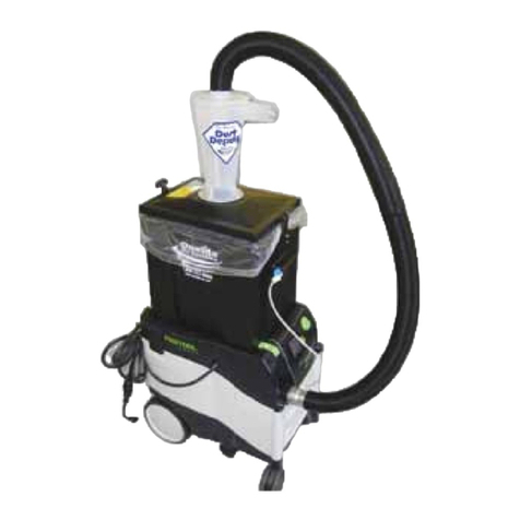
Oneida Air Systems Ultimate Dust Deputy User manual

Rev: 01/22/2020 Doc. #ZBM000036ULT
Appearance may vary slightly
Ultimate Dust Deputy
Systainer Cyclone
Separator Kit
# AXD000009
U.S. Pat.
6833016
RE40048
7282074
D638179

Oneida Air Systems2
System Start-Up Information
1. Do not vacuum anything that is burning or smoking, such as
cigarettes, matches, hot ashes, or any hot substance!
2. Do not vacuum (or use this cyclone near) ammable or combustible
liquids, gases, or explosive dusts, such as gasoline or other fuels,
lighter uid, cleaners, oil-based paints, natural gas, hydrogen, coal
dust, magnesium dust, grain dust, aluminum dust, sugar dust, our
dust or gun powder.
3. To reduce the risk of health hazards from vapors or dusts, do not
vacuum toxic materials unless a HEPA lter is used. Do not use or
store near hazardous materials.
4. Dust can be ammable and explosive. Some dust can be toxic or
cause allergic reactions.
5. Wood dust mixtures are highly ammable and can be explosive.
NEVER introduce sparks or sources of ignition into collector.
a. Empty drum aer each use.
b. Ground system.
6. NEVER leave wood dust in a building or vehicle.
7. Keep re extinguishers handy at all times.
8. Can be used for collecting non-ammable liquids.
9. Dispose of waste in a FIRE SAFE AREA.
READ THE SAFETY PRACTICES INSTALLATION AND
MAINTENANCE INSTRUCTIONS AND YOUR WET/ DRY
VACUUM’S OWNER’S MANUAL BEFORE ASSEMBLING
AND USING THE DUST DEPUTY
SOME DUSTS ARE HIGHLY FLAMMABLE OR
EXPLOSIVE. LEARN/ KNOW WHAT YOU ARE DEALING
WITH. FOLLOW ALL LOCAL, STATE, FEDERAL & NFPA
CODES AND GUIDE LINES.
3oneida-air.com
CAUTION! DISCONNECT VACUUM FROM ELECTRICAL
SOURCE BEFORE ANY OF THE FOLLOWING TESTS
ARE PERFORMED.
Maintaining Grounding Pathways
1. Use only tested anti-static components. Non anti-static hoses, couplers or connectors could
interrupt the anti-static pathway.
2. Make certain that the ground plug in your house wall socket is properly wired and working.
a. e anti-static pathway relies on the ground plug in your outlet to be functional.
b. Do not use two-prong to three-prong adapters, extension cords without a ground prong,
etc.
3. Install the Ultimate Dust Deputy per our instructions. is will ensure the anti-static pathway is
maintained.
4. Verify continuity through the anti-static pathway.
a. Continuity can be checked using a multi-meter that reads in mega ohms (see diagram
below for acceptable values).
b. CAUTION! Make sure that your vacuum is disconnected from any electrical source
before proceeding.
c. Check from end of hose to the earth ground prong on electrical plug.
5. Experiencing any static problems likely means the grounding path is interrupted. Be certain this
is resolved using these instructions or call us for assistance.
This diagram shows the
continuous pathway from the
grounding prong on the electrical
plug to the hose’s inlet.
The inlet of Festool®dust extractors incorporates a connection to the earth ground to provide a safe
discharge pathway for static electricity that may be generated when wood dust moves through hose
or plastic parts. This grounded inlet works in conjunction with anti-static hoses. Oneida wants to make
certain that our Ultimate Dust Deputy®customers understand that there is a grounding pathway that
must be maintained.
Oneida has always used static dissipating components in the Ultimate Dust Deputy. The UDD has been
third-party tested to function as specified.
megaohms / sq
17
15
13
11
9
7
5
3
1
-1
-3
-5
TARGET RANGE
Plastics
1012 & Up
Anti-Static
1010 –1012
Static Dissipative
106 –1010
Static Conductive
101 –106
Metals
10-1 –10-5

Oneida Air Systems4
System Dimensions
Nominal dimensions shown. Dimensions subject to slight
variations in manufacturing.
13-1/2"
343 mm
9-3/4"
248 mm
2" O.D.
1-7/8" I.D.
51 mm O.D.
48 mm I.D.
8"
203 mm
2" O.D.
1-7/8" I.D.
51 mm O.D.
48 mm I.D.
6-3/4"
171 mm

5oneida-air.com
System Dimensions
Nominal dimensions shown. Dimensions subject to slight
variations in manufacturing.
11-5/8"
295 mm
15-5/8"
397 mm
30-1/2"
775 mm
26-5/8"
676 mm

Oneida Air Systems6
System Contents
ID Part number Part description Qty
A VXC110009 Static Dissipative Cyclone with 2" Inlet and Outlet 1
B SDS090000 9 Gallon Dust Bin and Lid 1
C AXD2000060 2" x 55" Vacuum Hose 1
D RGZ000000* Dust Bin Gasket 4'
E RLH000009* 1/4" NPT x 1/2" Barb Straight Fitting 1
F VRV050500 1/2" Clear Vinyl Tubing 5'
G AHX000009 Hardware Kit 1
G1 AXG000004A Cyclone Gasket 1
G2 AFL000007 Rubber Latch 2
G3 ACB320000 Hose Clamp Band 1
G4 WGX000000 Wire Loop 2
G5 RMF000060A Foam Block 1
G6 VFA050015 Static Conductive Tape 2'
G7 AXD600103 2" SD Elbow 1
G8 AXD600104 2" SD Elbow with 1/4" NPT x 1/2" Barb Straight Fitting 1
G9 RCP050001 1/2" Vinyl Cap 2
G10 AXD600300 9-17 Gallon Drum Liner Bag 3
G11 AHK000009 Hardware Pack 1
G11A ———— 1/4" - 20 x 3/4" Phillips Pan Head SEMS Screws 6
G11B ———— 10-32 x 1" Phillips Pan Head SEMS Screws 4
Please unpack the parts carefully and conrm you have received each item listed here.
* Some components are pre-installed at the factory and are listed here for your convenience.
You will need the following:
• Phillips Head Screwdriver
• Wet/Dry Vacuum
• Vacuum Hose
• Vacuum hose adapters

7oneida-air.com
System Contents
B
A
C
F
G3
G5
G7G10
G4
G6
G8
G9
G11A
G2
G2
G11BG11B
G4
E
G1

Oneida Air Systems8
Assembly Instructions
read the Wire Loops (G4) through the Rubber Latches
(G2) and secure to the Dust Bin (B) as described in the
steps below to ensure proper static grounding [FIG. 1].
a. Push the Rubber Latch (G2) through the main body of
the Wire Loop (G4).
b. read the Wire Loop (G4) back through the circular
hole at the top of the Rubber Latch (G2).
c. read the Wire Loop (G4) back through the long
oblong hole in the Rubber Latch (G2) so the Wire
Loop’s terminal aligns with the latch’s top screw hole.
d. Insert two Screws (G11B) through the screw-holes on
the Rubber Latch (G2). e topmost Screw should be
inserted through both the Rubber Latch as well as the
terminal on the Wire Loop (G4).
1
FIG. 1
1.a
1.b
1.c
1.d
Front SIDE
G2
G4

9oneida-air.com
With a Phillips head screwdriver, attach the Rubber Latches
(G2) with the Wire Loops (G4) to the Dust Bin (B) using
the provided Screws (G11B) [FIG. 2].
2
FIG. 2
Assembly Instructions (Cont.)
Make sure that the handle of the Rubber Latch (G2) curves
downward when attached [FIG. 3].
Note: When the latch assembly is raised up the T-style handle
should point out and away from the Dust Bin (B).
3
FIG. 3

Oneida Air Systems10
A
A
B
B
H
H
I
I
A
A
B
B
H
H
I
I
Assembly Instructions
Insert the Foam Block (G5) into the hollow handle space
where the Straight Fitting (E) is installed within the Dust
Bin (B). is prevents material from being sucked into the
Straight Fitting (E) [FIG. 4].
Note: Clean the foam block regularly to ensure that airow to
the valve is not restricted.
4
If using a Bag, place a Liner Bag (G10) into the dust bin (B),
making sure to fully expand the bag by tucking it into the
corners. Fold the top of the bag over the top of the dust bin
[FIG. 5].
Note: e bag should lie at along the top edges of the bin
without signicantly bunching up.
5
FIG. 4
FIG. 5
G5

11oneida-air.com
Assembly Instructions (Cont.)
Place the lid onto the Dust Bin (B) and pull the Rubber
Latches (G2) up so that their topmost circular hole slips
over the tab protruding from each side of the lid [FIG. 6].
6
FIG. 6
Place Cyclone Gasket (G1) on top of the Dust Bin's Lid (B),
making sure to line up the bolt holes in the gasket with the
threaded inserts on the lid [FIG. 7].
7
FIG. 7

Oneida Air Systems12
Assembly Instructions (Cont.)
With a Phillips head screwdriver, attach the Cyclone (A)
to the Dust Bin Lid (B) using the provided Screws (G11A).
e cyclone’s side-facing inlet should be pointed towards
the shorter side of the lid [FIG. 8a]. Tighten the Screws in a
crisscrossing star pattern [FIG. 8b].
Note: Do NOT over tighten.
8
FIG. 8b
FIG. 8a
G11A

13oneida-air.com
Assembly Instructions (Cont.)
FIG. 9a FIG. 9b
If using a Bag, insert one end of the 1/2" Clear Vinyl Tubing
(F) into the Straight Fitting (E) located on one of the Dust
Bin’s (B) handles [FIG. 9a]. Press the Clear Vinyl Tubing (F)
in rmly. Tubing can be cut to desired length.
Note: If not using a bag, insert 1/2" Vinyl Cap (G9) into
the Straight Fitting (E) located on one of the Dust Bin’s (B)
handles [FIG. 9b]
9
Insert one end of the 1/2" Clear Vinyl Tubing (F) into the
2" SD Elbow's Nylon Straight Fitting (G8) [FIG. 10a]. Press
the Clear Vinyl Tubing (F) in rmly. Tubing can be cut to
desired length.
Note: If not using a bag, insert 1/2" Vinyl Cap (G9) into
the Straight Fitting (E) located on one of the Dust Bin’s (B)
handles [FIG. 10b].
10
FIG. 10a FIG. 10b

Oneida Air Systems14
Assembly Instructions
FIG. 11a
Position the 2" SD Elbow with Straight Fitting (G8) in one
of two locations: over the top port of the Cyclone (A) [FIG.
11A] or into your vacuum's grounded inlet [FIG. 11B].
Choose a location that best accommodates the length of
Vinyl Tubing (F) with your system.
Place the other 2" SD Elbow (G7) into the remaining
location.
11
FIG. 11b

15oneida-air.com
Ax Vacuum Hose (C) onto 2" SD Elbow (G7) . Attach the
other open end of Vacuum Hose (C) onto the tapered end
of the 2" SD Elbow with Straight Fitting (G8) [FIG. 12].
12
Assembly Instructions (Cont.)
Attach your vacuum’s standard hose to the Cyclone’s (A)
side-facing inlet. Secure with Hose Clamp (G3) if necessary
[FIG. 13].
Note: Make sure your hose is pushed rmly and fully onto
the inlet so that it does not slip o. e inlet is tapered and
shouldered to provide a rm friction t.
13
FIG. 12
FIG. 13
G3
A
C

Oneida Air Systems16
Top View
Top View
Top View
To Tools
To Tools
To Tools
Adding Cyclones to Improve Performance
Attach in Series
Attach in Parallel
Multiple Vacuums
Increases particle eciency
and helps in very ne dust
situations.
Same particle eciency but
increases the CFM.
More CFM/airow to larger
tools such as Table Saw,
Jointer, and Planer.
2 or More
200 CFM 100 CFM 100 CFM

17oneida-air.com
FAQ
Does the Dust Deputy work with the new Festool CT units
that have the T-Loc system to hold the systainer?
Yes! e Ultimate Dust Deputy is adaptable to all Midi and Mini
Festool vacs. e new vacs do require you to rotate the systainer
box 180 degrees.
Can I use this cyclone with smoldering or abrasive debris?
No. is cyclone is designed for use with light debris such as wood
dust. For applications with highly abrasive or smoldering materials,
we recommend our steel, Heavy-Duty Dust Deputy kits instead.
Will the Dust Deputy cyclone work if my tool has its own fan
blower?
In most cases, yes - but the cyclone's eciency will vary based on
whether your vacuum is also turned on.
e Dust Deputy cyclone needs a consistent airow rate to "spin"
the dust out of the airstream; If your tool's fan blower is pushing air
in while your vacuum is also sucking air out, this can disrupt the
airow rate and reduce the cyclone's separation performance.
In many cases, the fan blower on tools (such as planers) cannot be
turned o. If that is the case for you, try collecting your dust with
the vacuum turned o. In doing so you will be creating a positive
pressure system as the tool's fan blower pushes air through the Dust
Deputy cyclone. is method may not work with every vacuum.

Oneida Air Systems18
Troubleshooting
PROBLEM CAUSE SOLUTION
Not separating well.
(Only a tiny amount of
dust should reach the
vacuum)
Air leaks in the drum 1. Check for leaks between the lid and the dust drum.
2. Check for holes or leaks in the dust drum.
3. Check for leaks along the ange of the cyclone.
Material swirls in
cyclone and won't drop
into the dust container.
Material swirls in
cyclone and won't drop
into the dust container.
Collecting large bulky
material
1. Large, bulkier material might swirl. Restart or temporarily cut
o air ow to drop material down.
Low Air Volume System clogged 1. Clean vacuum and the vacuum lter per the manufacturer's
specs.
2. Check all hose connections for a blockage in the hose.
Hose Pulling o Hose connections not
tight
1. Due to the varied hose diameters, exible couplers can
be used.They are available at local hardware stores in the
plumbing section.
2. Use a hose clamp.
3. Wrap the inlet and outlet of the Dust Deputy with a layer of
electrical tape to increase the friction t.
4. Secure hose with a sheet metal screw.
5. Ensure the static grounding pathway is maintained via the use
of conductive tape and/or metal wire.
The dust bin doesn't
t on my Festool® CT
Mini/CT Midi Vacuum
Has the same
footprint as the
Systainer tool boxes
and will protrude
slightly over the edge
of the CT Mini and CT
Midi vacuums
1. For additional security with these vacuum models, we
recommend holding the Ultimate Dust Deputy down with
ratchet straps or bungee cords.

19oneida-air.com
Troubleshooting Air Leaks
Even a small leak can signicantly aect the overall
separation performance of the cyclone [FIG. 14]. If
you can't audibly pinpoint where the leak might be
coming from, one of the simplest ways to check for air
leaks is with a smoke test. You can usually nd smoke
test kits at any hardware store (typically in the HVAC
section). While the system is running move the smoke
tester around the unit. If at any time you see the
incense smoke being drawn into the system, you’ve
found an air leak that needs to be sealed.
FIG. 14
Leak Point
Leak Point
Leak Point
Leak Point
Leak Point
Leak Point

Oneida Air Systems20
Grounding Accessories
Oneida Air Systems always recommends using static conductive hoses and components
with your cyclonic vacuum system.
If a non-conductive component is used, the grounding pathway must be continued
via Static Conductive Tape (G6) or wire to bridge the gap between the non-conductive
components. By bridging this gap, the anti-static grounding pathway will be maintained
Non-Conductive, 3rd Party Accessory
Hoses, Fittings, Adapters, Wands, etc.
Conductive Hose
Conductive Hose Conductive Tape
Conductive Wire
Other manuals for Ultimate Dust Deputy
1
Table of contents
Other Oneida Air Systems Vacuum Cleaner manuals

Oneida Air Systems
Oneida Air Systems Dust Cobra User manual

Oneida Air Systems
Oneida Air Systems Dust Cobra - XCK010000 User manual

Oneida Air Systems
Oneida Air Systems AXD000009 User manual

Oneida Air Systems
Oneida Air Systems Ultimate Dust Deputy User manual

Oneida Air Systems
Oneida Air Systems 10 Gallon User manual

Oneida Air Systems
Oneida Air Systems CC500 User manual