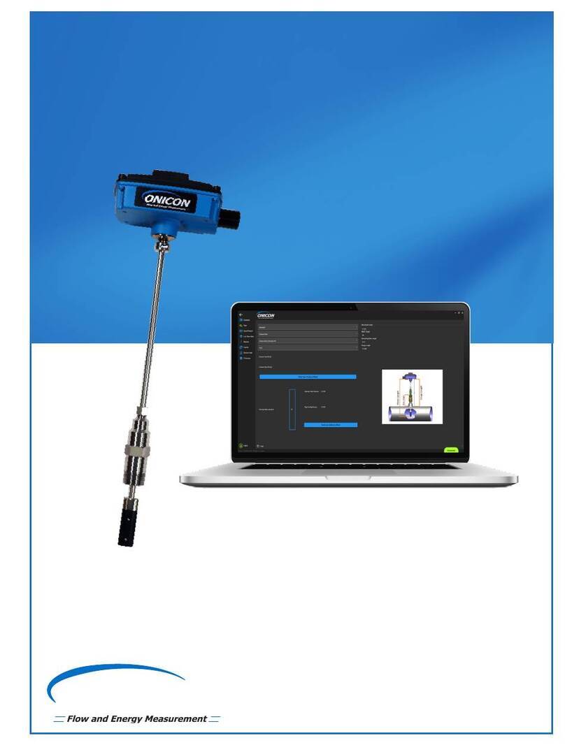
Onicon SYSTEM-30 Operating instructions
Other Onicon Measuring Instrument manuals
Onicon
Onicon F-1000 SERIES Operating instructions
Onicon
Onicon F-3200 Series Original operating instructions
Onicon
Onicon System-10 BTU Meter User manual
Onicon
Onicon SYSTEM-40 Operating instructions
Onicon
Onicon SYSTEM-20 Operating instructions
Onicon
Onicon F-5100 Inline Operating instructions
Onicon
Onicon System-10 BTU Meter User manual
Onicon
Onicon D-100 Operating instructions
Onicon
Onicon D-1401 Operating instructions
Onicon
Onicon F-4000 Series Assembly instructions
Onicon
Onicon System-10 BTU Meter Operating instructions
Onicon
Onicon F-1500 Series Operating instructions
Onicon
Onicon F-1100 Series User manual
Onicon
Onicon F-2600 Series Operating instructions
Onicon
Onicon System-10 BTU Meter Operating instructions
Onicon
Onicon Fox Thermal FT4X User manual
Onicon
Onicon D-100 User manual
Onicon
Onicon F-4300 Original operating instructions
Onicon
Onicon F-5100 Inline Operating instructions
Onicon
Onicon F-4300 Original operating instructions
Popular Measuring Instrument manuals by other brands

Powerfix Profi
Powerfix Profi 278296 Operation and safety notes

Test Equipment Depot
Test Equipment Depot GVT-427B user manual

Fieldpiece
Fieldpiece ACH Operator's manual

FLYSURFER
FLYSURFER VIRON3 user manual

GMW
GMW TG uni 1 operating manual

Downeaster
Downeaster Wind & Weather Medallion Series instruction manual

Hanna Instruments
Hanna Instruments HI96725C instruction manual

Nokeval
Nokeval KMR260 quick guide

HOKUYO AUTOMATIC
HOKUYO AUTOMATIC UBG-05LN instruction manual

Fluke
Fluke 96000 Series Operator's manual

Test Products International
Test Products International SP565 user manual

General Sleep
General Sleep Zmachine Insight+ DT-200 Service manual


