SOMMY ER9 Series User manual

KKER9C02-A0-page 1
⊙
320*340 TFT color LCD display.
⊙
Measure 3 phase voltage , ampere , reactive power ,active power , apparent power , power factor , frequency , Kwh , KvarH ect.
⊙
Three phase voltage , ampere , active power , reactive power ,and other parameters real time record and curve record storage
⊙
Total Kwh and total KvarH accumulation memory function.
⊙
Both side and outside storage , support SD card and USB storage , maximum storage is 4GB
⊙
Switch output: AL1, AL2 relay switch output
⊙
Analog output : one 4-20mA DC transmition output.
⊙
Switch input :4 switch input S1-S4 , used in remote control the electric swith status.
⊙
With RS485 communication , Modbus RTU
⊙
Optional tariff statistics function, with demand statistics function.
⊙
Optional harmonic analysis funtion (including the total harmonics).
⊙ Backup data can be opened by PC software to show the real time curve record
Features:
※
Caution
Warning
2
ER9 Series 3 Phase Multi-function Power Recorder Operation Manual
This meter can measure and record the true value of voltage , ampere ,
active power , reactive power , power factor , Kwh , KvarH ect. It also
can generates various kinds of report forms . The parameters can copy
to SD card or USB automatically or by manual .
With RS485 communication port , support modbus RTU. It can be widly
used in SCADA system and energy management system , power station
automation system , power grid , estate power monitor , intelligent building ,
intelligent switchboard and switch cabinet ect
For your safety , please read the content before usage.
Safe Caution
please read the manual carefully before using the meter .
Please comply with the below important points:
Warning An accident may happen if the operation does not comply
with the instruction.
Notice An operation that does not comply with the instruction may lead
to product damage.
The instruction of the symbol in the manual is as below:
An accident danger may happen in a special condition.
1. A safety protection equipment must be installed or please contact with
us for the relative information if the product is used under the circumstance
such as nuclear control, medical treatment equipment ,automobile, train,
airplane, aviation, entertainment or safety equipment, etc. Otherwise, it may
cause serious loss, fire or person injury.
2. Apanel must be installed, otherwise it may cause creepage (leakage).
3. Do not touch wire connectors when the power is on, otherwise you may
get an electric shock.
4. Do not dismantle or modify the product, If you have to do so, please
contact with us first. Otherwise it may cause electric shock and fire.
5. Please check the connection number while you connect the power supply
wire or input signal, otherwise it may cause fire.
1. This product cannot be used outdoors. Otherwise the working life of the
product will become shorter, or an electric shock accident may happen.
2. When you connect wire to the power input connector or signal input
connectors, the moment of the No.20AWG (0.50 mm2) scrwew tweaked
to the connector is 0.74n.m-0.9n.m. Otherwise the connectors may be
damaged or get fire.
3. Please comply with the rated specifications. Otherwise it may cause fire
after the working life of the product becomes shorter.
4. Do not use water or oil base cleaner to clean the product. Otherwise it
may cause electric shock or fire, and damage the product.
5. This product should be avoid working under the circumstance that is
flammable, explosive, moist, under sunshine, heat radiation and vibration.
6. In this unit it must not have dust or deposit, otherwise it may cause fire
or mechanical malfunction.
7. Do not use gasoline, chemical solvent to clean the cover of the product
because such solvent can damage it. Please use some soft cloth with
water or alcohol to clean the plastic cover.

KKER9C02-A0- page 2
1.
2.
4.
6.
7.
install bracket
Operation Manual
PC software
USB
SD
2
1
1
1
1
used for panel installation and fixing
Printed Manual
Disk(USB/SD Card)suitable for Win2000/WinXP/WinVista/Win7
Maximum support 8GB
Maximum support 8GB
Instrument accessories
No. Name Quantity Note
Power Consumption ≤8VA
Frequency
40~60Hz、Accuracy:0.1Hz
Working Environment
work temperature:-10℃~+45℃,
Humidity
<85%RH no condensation,Work temperature limit:-25℃~+55℃,
Storage temperature:-25℃~+70℃,
Analog Output
Alarm Output
4 On/Off output, 250VAC/3A or 30V DC/5A
Dimension
96W×96H×100Lmm
input VS power: AC 2000V, Power VS relay :AC 2000V,Power VS transmition output:DC 2000V,
RS485 port,isolated low voltage or I/O: DC 600V
Min.116
Min.116
91.0
-0.0
+0.5
-0.0
+0.5
91.0
Technical Parameters
Connection 3 phase 3 wires, 3 phase 4 wires
Voltage Range AC 3x57.7V / 3X220V (note: Direct input volt: L-N: 0~600V, L-L: 0~1000V)
Voltage Overload Continuous: 1.2 times Instantaneous: 2 times/10S
Voltage Consumption <1VA (each phase)
Voltage impedance ≥300KΩ
Voltage Accuracy RMS measurement , Accuracy : 0.5
AC 0.025 ~ 5A
Current Range
Current Overload Continuous: 1.2 times Instantaneous: 4 times/10S
Current Consumption <0.4VA (each phase)
Current impedance <20mΩ
Current Accuracy RMS measurement , Accuracy : 0.5
Energy Active energy accuracy 0.5 / Reactive energy accuracy 1.
Power Active power/Reactive power/Apparent power, accuracy: 0.5
Display
TFT color display
Power Supply AC/DC 100 ~ 240V
Output Digit Interface RS-485 Modbus-RTU Protocol
1 transmition output, 4-20mA DC Load<400Ω
Anti-jamming
Electrostatic interference resistance ability :IEC61000-4-2,Level 2
Radiation anti-jamming capacity: IEC61000-4-3,Level 3
Fast transient pulse interface:IEC61000-4-4,Level 4
Surge immunity(1,2/50us-8/20us):IEC61000-4-5,Level 4
Isolation&puncture
Insulation Input/output/power supply to Meter cover >5MΩ
Dimension and Mounting Size
Side size Hole size
Make the lock button aim at
the open hole , and push it
to front to lock well. Then
adjust the screwto make
adjustment for installation.
adjustment screw
standard configuration
standard configuration
standard configuration
standard configuration
standard configuration
standard configuration
1
2
3
4
5
6
KKER9C02-A0-page 3
2
1
34
5
6
USB port
SD card
SET
ESC
A
B
C
N
24 25 26 28 29
27 23
21 22
20 23
21 22
20
A
B
C
N
Current input via CT
A
B
C
24 25 26 28 29
27 23
21 22
20 23
21 22
20
A
B
C
* *
4
~20mA
NC
DO2 AL2
NO NC NO
AC/DC
100
~240V
COM
+-
DO1 AL1 POWER
Ua
B-
A+SCOM
S1
S2S3S4RPAPGND
UbUcUnla (Ub) (Uc) (Ua)
lblclc lb la
1
21
1112131415161819 17
2223242526272829 20
10
23456789
Wire Connection
Note: 1. For voltage input connection terminal,bracket terminals (Ua) (Uc) (Ub) shows 3 phase 3 wire connection method,
2. Current input is current input terminal , all the inputs and outputs must be coherent
Model 1: (3pcs CT) 3 phase 4 wire working mode Model 2: (2pcs CT): 3 phase 3 wire working mode
Current input Voltage input
Voltage direct input
Voltage input via PT
Current input
Current input via CT
Voltage input
Voltage direct input
Voltage input via PT
Explanation :
A. Voltage input: Input voltage should not be higher than the rated input voltage of meter, otherwise a PT should be used.
B. Current input: Standard rated input current is 5A. A CT should be used when the input current is bigger than 5A. If some other meters are
connected with the same CT , the connection should be serial for all meters.
C. Please make sure that the input voltage is corresponding to the input current, they should have the same phase sequence and direction,
otherwise data and sign error may occur (power and energy).
D. The connection mode of meter which is connected to power network should depend on the CT quantity. For 2pcs of CT, it should be 3 phase
3 wire connection. For 3pcs of CT, it shoud be 3 phase 4 wire connection.
E. Please pay high attention on the difference between 3 phase 3 wire and 3 phase 4 wire connection , becasue wrong connection may lead to
incorrect calculation of power factor, power and energy .
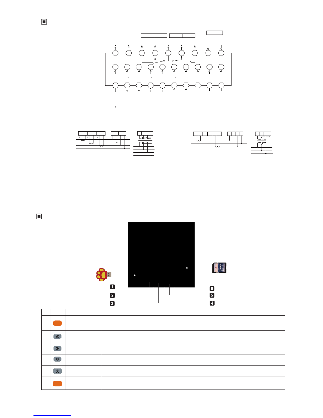
Panel Indication
Set Key
Left Key
In measure interface, energy,harmonics, tariff rate, record, event interface, used to back to
guide page . In setting interface , select the menu or parameter need to be modified, and press
Set key to make confirmation after finishing modification.
move cursor to left: in parameter modifying interface, used to select the menu and modified parameter.
Right Key
page down: in running interface , used to turn to back page.
move cursor to right: in parameter modifying interface, used to select the menu and modified parameter.
page up: in running interface , used to turn to front page.
Decrease Key parameter modification: used to decrease value in parameter modification interface.
Increase Key parameter modification: used to increase value in parameter modification interface.
Return Key In menu operation, it is used to return to previous menu
No. symbol Name Function
KKER9C02-A0-page 4
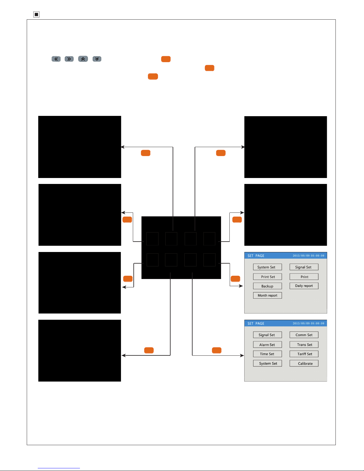
Page Guide
SET
SET SET
SETSET
SETSET
SET
SET
SET
ESC
Press
。
In initial status, meter will come to guide page after power on . There are instantaneous parameters, energy, harmonics
measurement, tariff rate kwh, energy record, event record and meter setting and display setting in guide pages ..
to move cursor . Press to enter subpages accordingly.
In electrical , energy, harmonic, tariff, record and event page, press to back to guide page.
In meter set and display set interface , press to guide page interface.

KKER9C02-A0-page 5
Instant Electric Parameters Page Operation Process
SET
In “electrical” interface , press key to shift the page. In any pages , press to back to guide page.
In the bottom of display interface , there is press key operation remind
Energy Interface Operation
SET
In “ energy ” interface , press key to shift the page. In any pages , press to back to guide page.
In the bottom of display interface , there is press key operation remind

KKER9C02-A0-page 6
Harmonic Page Operation
Tariff Rate Operation
SET
In “electrical” interface , press key to shift the page.
In the bottom of display interface , there is press key operation remind
In any page , press to back to guide page.
Note: This function is not available now
SET
In “tariff ” interface , press key to shift the page. In any pages , press to back to guide page.
In the bottom of display interface , there is press key operation remind

KKER9C02-A0-page 7
Record Interface Operation
Event Record Process
SET
In “ record ” interface , press key
to shift the page . Press to back to guide
page .
In the bottom of display interface , there is
press key operation remind
SET
In “electrical” interface , press key to shift the page. In any pages , press to back to guide page.
In the bottom of display interface , there is press key operation remind
1. realtime curve display operation

KKER9C02-A0-page 8
SET
SET SET
SET
SETSET
SET
SET
//
SET
SET
ESC
SET
SET
ESC
1
2
3-3/3-4
0~999.9
10~999.9
0~9999
0~999.9
1~247
1200/2400/4800/9600/19200
0/1
1~247
1200/2400/4800/9600/19200
0/1
Meter Parameter Set Operation Process
Submenu operation in configuration setting interface
In measuring status , press to enter into code password interface. Press to input
In the interface , press or to choose submenu to be operated. When the corresponding setting frame show blue background , press to
enter operation menu. In operation interface , press or to choose the data frame to be modified. When it is blue or black background , press
to modify value or press to show data input dialog box . In dialog box , press or to select to delete, cancel or modify operation. After
finishing value modification , press
to confirm and exit the interface . It will appear whether save the
dialog box , select yes to storage the value and exit.
to return the operating menu. Press
/
to move to password cursor , press
password , press to confirm to enter configuration set interface.
No. class 1 class 2 description range
Signal set
Link Select the input network of the measured signal
PT (Pri)
PT (Sec)
Primary coil voltage , unit kV
Secondary coil voltage , unit V
CT (Pri)
CT (Sec)
Primary coil current , unit A
Secondary coil current ,unit A
Comm. Set
communication 1
communication 2
( can be ordered)
Address meter address range
baud rate Baud rate
Data sequence Data sequence: high digit in front or low digit in front
Address
baud rate
Data sequence
Baud rate
Data sequence: high digit in front or low digit in front
meter address range

KKER9C02-A0-page 9
0
~2
0
~999.9
0
~999.9
0
~1
0
~99
0
~99
0
~68
0
~2
0
~999.9
0
~999.9
0
~999.9
0
~10
0
~1
0
~999.9
0
~999.9
0
~999.9
0
~1
0
~99
0
~99
1
~32
1
/K/M
0
~999.9
0
~999.9
0
~3
0
~3
0
~3
0
~3
0
~3
0
~95
0
~95
0
~95
0
~95
0
~95
select 12/24
set correct time
1
~32
1
/K/M
0
~68
7
4
5
6
3
Mode
year month day hour minute second
1
2
3
7
8
1
2
3
7
8
Initial
8
Alarm Set
Alarm 1
Alarm 4
mode
unit
value
backlash
output
ON-DLY
OFF-DLY
When value is 0 , it is for remote control mode, otherwise it is for alarm mode. Please refer to table 1.
1: international standard unit, K: 1000 times standard unit, M: means1000000 times standard unit.
1st alarm value setting
1st alarm hysteresis value setting
1st alarm relay output setting
alarm start delay time , unit : second
alarm finish delay time , unit : second
mode
unit
value
backlash
output
ON-DLY
OFF-DLY
When value is 0 , it is for remote control mode, otherwise it is for alarm mode. Please refer to table 1.
1: international standard unit, K: 1000 times standard unit, M: means1000000 times standard unit.
4th alarm value setting
4th alarm hysteresis value setting
4th alarm relay output setting
alarm start delay time , unit : second
alarm finish delay time , unit : second
Trans Set
Please refer to table 1
Unit
High
Low
1: international standard unit, K: 1000 times standard unit, M: means1000000 times standard unit.
Transmit output 20mA
Transmit output 4mA
Trans 1
Trans 2
can be ordered
Please refer to table 1
Mode
Unit
High
Low
1: international standard unit, K: 1000 times standard unit, M: means1000000 times standard unit.
Transmit output 20mA
Transmit output 4mA
Time set
time
mode
Date-time
time mode 24 hours
Tariff Setting
tariff
start time
calibrate
Period 1 tariff means
tine tariff, Peak tariff, flat tariff, vale tariff
Period 2 tariff means
tine tariff, Peak tariff, flat tariff, vale tariff
Period 3 tariff means
tine tariff, Peak tariff, flat tariff, vale tariff
Period 7 tariff means
tine tariff, Peak tariff, flat tariff, vale tariff
Period 8 tariff means
tine tariff, Peak tariff, flat tariff, vale tariff
Period 1 start time
Period 2 start time
Period 3 start time
Period 7 start time
Period 8 start time
System Set
Volt min
Cur. Min
Comm. delay
Energy Mode
set minimum value of voltage
set minimum value of current
set communication delay , unit:ms
energy calculation mode . 1 means primary calculation. 2 means secondary calculation
Extend 1
Extend 2
Extend 3
Extend 4
for spare
for spare
for spare
for spare
Clr. Kwh
Clr. Demand
reset to factory default setting
clear kwh
clear demand
Clr. Event clear event
password factory setting , not opened
:Divide 24 hours a day into 96 segments, every 15 minutes as one segments. For example, the corresponding time for segment 0 is 0 o'clock,
the corresponding time for segment 10 is 2:30. Please notice that, the setting of period 1 to period 12 should be from small to big.
Note

KKER9C02-A0-page 10
Note: ①The above alarm setting values are positive number without symbol , not support negative value setting.
②
③Alarm delay unit is second.
1
3
1 1
2 2
2
4
30
31
29
30
31
32
33
34
57
59
61
58
60
62
29
(FL)
(EPL)
(EQL)
(FH)
(EPH)
(EQH)
(F)
(EP)
(EQ)
3263 64(InL) (InH) (In)
65
67
66
68
(UNNB)
(INNB)
(ULNB)
(PNNB)
(UaL)
(UbL)
(UaH)
(UbH)
(Ua)
(Ub)
53
55
27
28
54
56
27
28
(PFcL)
(PFLL)
(PFcH)
(PFLH)
(PFc)
(PFL)
11 11
12
12
13
14
14
15
16
16
17
18
20
12
13
14
15
16
17
5
7
9
11
13
15
17
19
22
24
26
28
30
32
34
3 3
4 4
5 5
6 6
6
77
88
8
99
10 10
10
21
23
25
27
29
31
33
(UbcH)
(UcaH)
(ULH)
(IaH)
(IbH)
(UbcL)
(UcaL)
(ULL)
(IaL)
(IbL)
(IcL)
(IL)
(PaL)
(PbL)
(PcL)
(PL)
(QaL)
(IcH)
(IH)
(PaH)
(PbH)
(PcH)
(PH)
(QaH)
26 51 52 26
18
19
20
21
22
18
19
20
21
22
23
24
25
23
24
25
36
38
40
42
44
46
48
50
35
37
39
41
43
45
47
49
(QbL)
(QcL)
(QL)
(SaL)
(SbL)
(ScL)
(SL)
(PFaL)
(PFbL)
(QbH)
(QcH)
(QH)
(SaH)
(SbH)
(ScH)
(SH)
(PFaH)
(PFbH)
(Qb)
(Qc)
(Q)
(Sa)
(Sb)
(Sc)
(S)
(PFa)
(PFb)
(UcL)
(UL)
(UabL)
(UcH)
(UH)
(UabH)
(Ubc)
(Uca)
(UL)
(Ia)
(Ib)
(Ic)
(I)
(Pa)
(Pb)
(Pc)
(P)
(Qa)
(Uc)
(U)
(Uab)
Reference table 1: Reference table for alarm output and transmit output
No. Parameter switch output code low alarm switch output code high alarm transmit output code 4-20mA
Ua (A phase voltage)
Ub (B phase voltage)
Uc (C phase voltage)
U (phase voltage of A, B or C)
Uab (AB line voltage)
Ubc (BC line voltage)
Uca (CA line voltage)
UL (line voltage of AB, BC or CA)
Ia (A phase current)
Ib (B phase current)
Ic (C phase current)
I (A , B or C phase current)
Pa ( A phase active power )
Pb ( B phase active power )
Pc ( C phase active power )
Ps ( total active power )
Qa( A phase reactive power)
Qb( B phase reactive power)
Qc( C phase reactive power)
Qs ( total reactive power )
Sa ( A phase apparent power )
Sb ( B phase apparent power )
Sc ( C phase apparent power )
Ss ( Total apparent power)
PFa (A phase power factor)
PFb( B phase power factor)
PFc( C phase power factor)
PFs (Total power factor)
Frequency
EP (total kwh)
netural line current
EQ (total kvarh)
unbalance
unbalance
Power factor only support one decimal point.
KKER9C02-A0-page 11
Backup by manual
①
②
③
④
⑤
⑥
⑦
backup successfully
S D
SET
SET
SET
SETSET
2016-08
2016-01:0.00
2016-02:0.00
2016-03:0.00
2016-04:0.00
2016-05:0.00
2016-06:0.00
2016-07:0.00
2016-08:185.20
2016-09:0.00
2016-10:0.00
2016-11:0.00
2016-12:0.00
:185.20
∑185.20
Monthly report
2016-08-15 09:47:58
Year Total
Active power
TimeType
2016-08
01:0.00
02:0.00
03:0.00
04:0.00
05:0.00
06:0.00
07:0.00
08:0.00
09:0.00
10:0.00
11:0.00
12:0.00
13:0.00
14:0.00
15:185.20
16:0.00
17:0.00
18:0.00
19:0.00
20:0.00
21:0.00
22:0.00
23:0.00
24:0.00
25:0.00
26:0.00
27:0.00
28:0.00
29:0.00
30:
31:
0.00
0.00
:185.20Month Total
∑185.20
Active power
Daily report
2016-08-15 09:47:58
TimeType
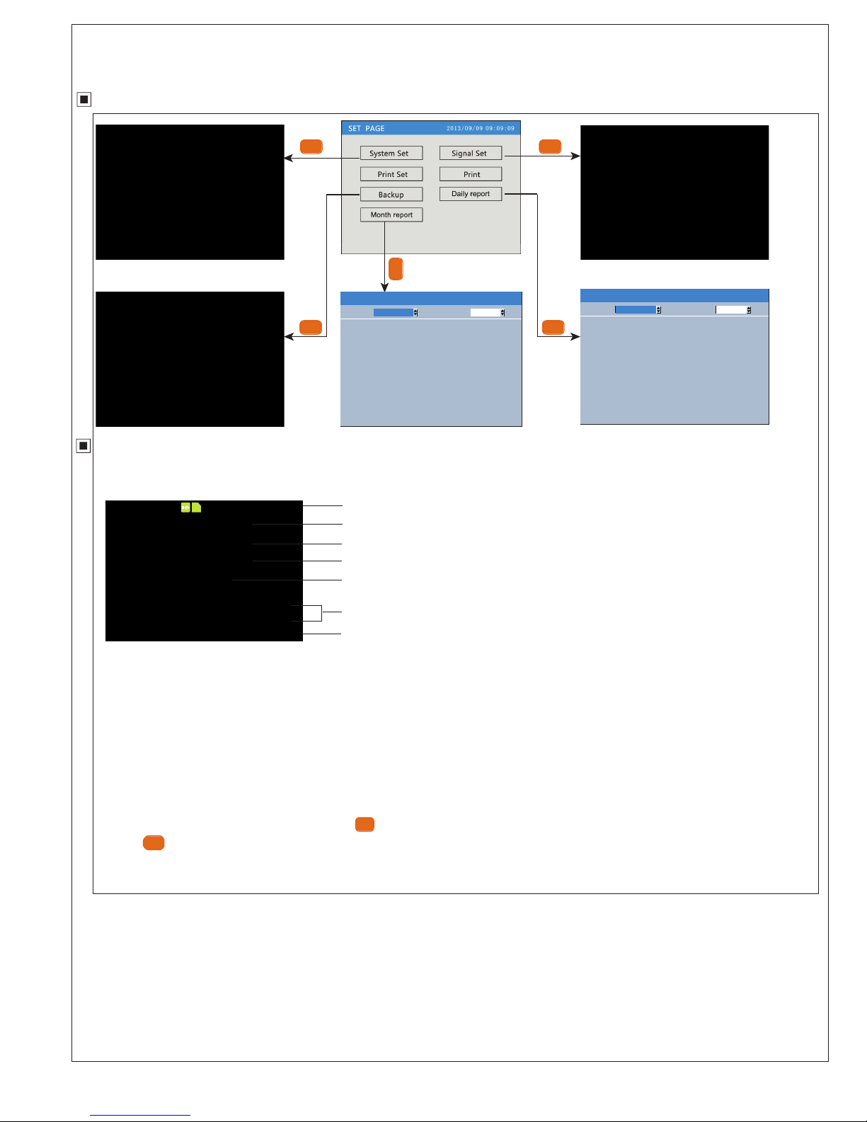
Record Backup Operation Process
Data Backup Operation
1. Data Backup Page Operation
1. Status bar shows interface name , USB & SD card connection status
2. From : Data backup start time
3. To : Data backup end time
4. Backup content : include all history data record , alarm record , accumulated
daily report form , monthly report form .
5. Backup file name : present data + file serial number.
6. Backup the file to USB or SD card
7. Backup progress bar and backup status display.
SET
ESC
1. Confirm USB or SD card connect well with power recorder , check
the SD card or USB status remind on the status bar.
2. Set backup data start time
3. Set backup data finish time
4. Set the backup file content .
5. Confirm the file name , file name format , data and serial number.
6. Move cursor to backup USB / SD card , and press to confirm
backup.
7 . Press key to return function list interface after finishing backup.
Auto-Backup
1. When insert the SD card to power recorder, and it reminds that
the status is normal , then the recorder will backup the data to the
SD card automatically at 0:00 and 12:00 every day.
2. During backup , it will appear a blue progress bar , after finishing
backup , the progress bar will disappear. If backup failed or SD
card is full , it will keep displaying red progress bar.
backup illustration:
1. please use formated SD or USB , use FAT32 version.
2. please use PC to format SD card or USB.
3. USB port: support USB2.0 protocol , maximum capacity is 4GB.
4. SD card port: standard SD card , maximum capacity is 4GB.

KKER9C02-A0-page 12
1. Adjust input parameter
2. Edit input parameter
Modify setting Item
zIME 2 .
Ammeter
1234567890 .
-
Delete
Cancel
输入面板
SET
Backup file name
Export data
daily
report
3
4
5
2
1
select the export data
power curve high / low
limit
Configuration Setting Menu Function
No.
Menu Submenu Description
System
set
Signal
set
backup
monthly
report
Alias Can modify the name of the meter , ex-factory setting is Ammeter
Default view
Interval
Standby time
Password
System language
Factory set
Purge data
Purge accu
Main display interface , integrated parameters is default screen
record time interval, default is 1second
screen display rest delay time , when set as 0 , no display rest delay function , default value is 10minutes
Password modification . The password can be modified , ex-factory setting is 000000
Chinese and English can be shift
Recorder will return all parameters to factory setting when confirm this function.
Clear all the record data
Clear accumulated power energy to zero
voltage curve high/ low limit
current curve high/ low limit
power factor curve high
/ low limit
Input voltage high limit and low limit , default setting is 300 and 0
Input current high and low limit , default setting is 10 and 0
Each phase power high and low limit , default setting is 100 and 0
Each phase power factor low and high limit , default setting is 1 and 0
From Data backup start time
Data backup end time
to
Backup file name
backup to USB
backup to SD
backup to USB
backup to SD
record kwh everyday
record kwh every month
record kwh everyday
record kwh every month
number
ok
number
ABC
abc *** piny
There are three type modification: adjust input parameter,edit input parameter,select input parameter
Using and to adjust the content which cursor is on.
SET
SET
SET
SET ESC
User can input data、capital letter、small letter、symbols 、characters by input panel.
3. Select input parameter
Press and to popup select list , press to move and select cursor,
Move cursor to the parameters to be modified , press
operate input by input panel.
If edit data , press and to ajust the parameter , press
to popup input panel .
to confirm content.
press Press
to cancel the selection .
to popup input panel, user can
Warning: must input the name to square frame ,cannot be empty. Not support chinese characters
Input Panel Operation:
:When cursor is in Piny, can switch the Pinyin and character.
Delete : delet the last letter in input column
Cancel: exit input panel, cancel editting.
OK : exit form input panel , and confirm the editting.
If cursor is the position of input type item , press
ok to confirm the input type.
:
Move the soft keyboard cursor ( include function , input type ,
PinYin or character choice)
:When cursor is in 123 , ABC , abc , *** , input the letter in the cursor
position into display column.
KKER9C02-A0-page 13
Curve Record Operation
①
②
⑤
⑥
⑦
⑧
④
③
①
②
④
⑤
⑥
③
⑦
80%
04:55 05:35 06:15 06:55 07:35 08:15
60%
40%
20%
A: 240. 0 V B: 160. 0 V C: 80. 0 V
2 0 1 2- 0 8- 1 5 09: 4 7: 58
80%
60%
40%
20%
A: 240. 0 V B: 160. 0 V C: 80. 0 V
2 0 1 2- 0 8- 1 5 09: 4 7: 58
time:
2 0 1 2- 0 8- 1 5 09: 4 7: 58
Cursor
SET
1. realtime curve display operation show
2. history curve record operation show
voltage realtime curve
voltage history curve
1. Status bar display
Display interface name , data and time
: means use or key to shift the display interface.
2: real time of the record
7: curve display percentage scale
8: present interface curve corresponding measure value.
3. grid : easy for check record curve in each grid or layout
4. A phase real time record curve , the color is the same with A
phase measuring data
5. B phase real time record curve , the color is the same with B
phase measuring data.
6. C phase real time record curve , the color is the same with C
phase measuring data
1. Display history record interface name , data and time
2. Data recall mode : recall mode and cursor mode . Press
to shift the mode.
3. Recall time : present cursor corresponding time .
4. Recall bar : convenient for user to locate time and data . In
cursor mode , press to move location to left and right.
5. Data history curve , display 3 phase data by three different curve
7. 3 phase history data : Display the history data of recall bar
located position.
6. Scale : curve display percentage scale
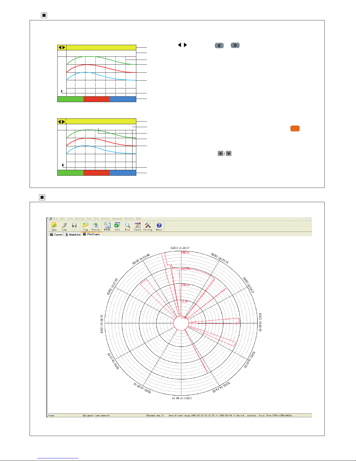
Standard Software Usage Brief

KKER9C02-A0-Page 14
Output Function
1. Energy pulse
ER9 provides the function of energy calculation, with 2 energy pluse output AP & RP, and RS485 interface for the transmit of energy data.
The energy pulse of optical couple relay with open collector enables the long distance transmit of active energy AP & reactive energy RP. Remote
PC terminal, PLC, DI On-Off output and collector module are applied to collect the pulse of energy meter to enable the energy cumulation
calculation. Besides, this output mode is also the energy accuracy check way (National metrology regulations: Standard meter pulse tolerance
comparison method)
(1). Electrical characteristic: the output of optical couple relay with open collector , V≤ 48V, Iz≤ 50mA
(2). Pulse constant: 9000imp/kwh. It means the impulse output No. is 9000 when the energy meter counts up to 1KWH.
The piont should be emphasized is that the above 1kwh is for the 2nd coil energy. Supposed that PT and CT is connected , the primary coil energy
that 9000 pulse refer to is equal to 1kwhX voltage transform PT X current transform CT.
2. Remote measure and remote control function: 4 loops S1-S4 are used to remote measure electric ON/OFF status. DO1 & DO2 function can be
used to remote control electric devices. When using Do function, alarm mode should be setted as 0, otherwise DO1 and DO2 will be as AL1, AL2
output. DO1 DO2 function control value is writen via RS485 interface.
3. Communication function ( please refer to the communication protocol)
4. Transform output( please refer to table 1)
5. Alarm function (please refer to table 1)
6. Data record report output , backup the data to SD card or USB . We offer software to make analysis the data on PC.
4. Preview print history curve,data list , circle diagram.
5. Make history data statistics by statistics functions in tools menu.
6. Language menu set Chinese or English display.
7. In history curve display interface , make history curve analysis in section by editing add tag , tag management, curve hidden function.
PC Software Function
1. Used to open and check the data in SD card or USB , files version type is date.EDZ or Date.files series number
2. Make history data analysis by history curve , data list, circle diagram display.
3. Export excel data.
Table of contents
Other SOMMY Measuring Instrument manuals


