1
1451
Belcher
Road
South,
Largo
FL
33773
•
USA
•
T
el
+1
(727)
447-6140
•
Fax
+1
(727)
442-5699
•
[email protected]F-1500 Turbine Flow Meter Manual 02/18 - 1018-6 / 35726 Page 10
1.4 Flow Meter Conguration
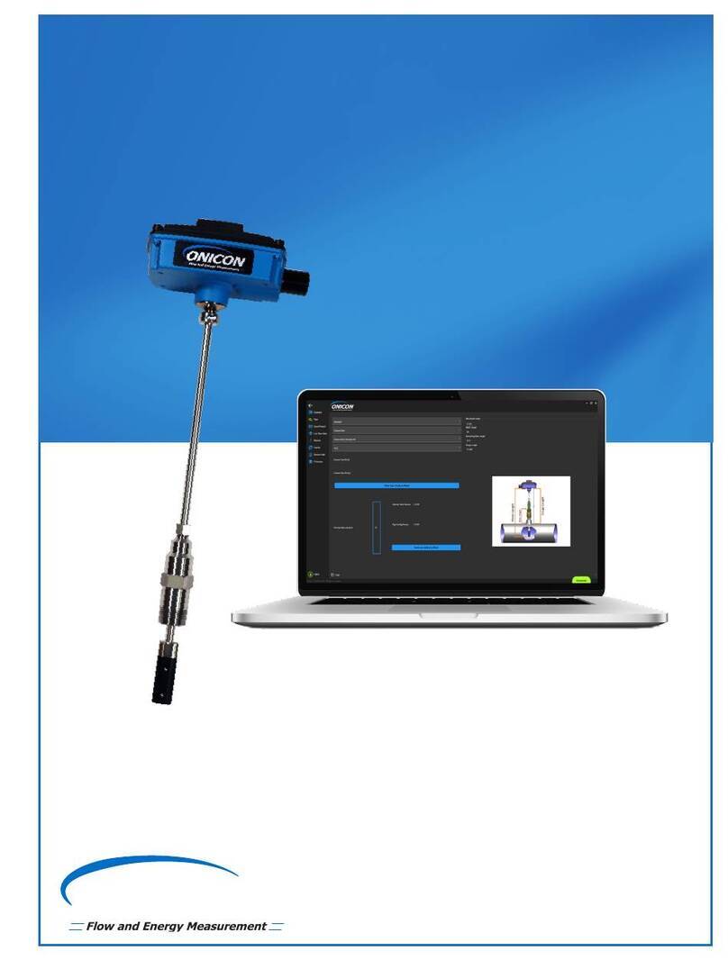
The F-1500 Insertion Turbine Mass Flow Meter has a sensing head which contains the turbine
rotor, temperature sensor, and pressure tap. The pressure sensor, if provided, is located in the
pressure transducer housing between the stem and electronics housing.
The meter is installed through a full block valve and mounting adapter having a clear,
cylindrical port diameter of 1.875” diameter. It can be installed during system downtime or
using standard “Hot Tap” procedures.
The meter directly monitors the velocity at a point in the cross-sectional area of a pipe, duct, or
stack. The velocity at a point in the pipe varies as a function of the Reynolds number. When a
uid ows through a pipe, the velocity generated is not constant across the diameter. The uid
velocity varies across the diameter of the pipe creating a “Velocity Prole”. That is, velocities
near the center of the pipe are faster than those nearer to the wall. In addition, the velocity prole
varies in concert with ow rate from the lowest to the highest ows. Mathematical descriptions
of this prole have been developed for over 100 years. By knowing the velocity prole and the
ow rate at a single point, the average ow rate can be determined. The accuracy of the ow rate
computation depends on adherence to the piping installation requirements given in Chapter 2. If
adherence to those guidelines cannot be met, contact the factory for specic installation advice.
1.4.1 Multivariable Options
Different versions of the meter are capable of providing the following ow measurement options:
Volumetric ow; Mass ow with temperature compensation; Mass ow with temperature and
pressure compensation; Steam energy ow with temperature compensation; Steam energy
ow with temperature and pressure compensation, Mass or Energy ow with temperature and
external pressure compensation and Net Energy using a second temperature sensor.
1.4.2 Line Size / Process Connections / Materials
The F-1500 can be used in line sizes 2” and greater and is built with a packing gland design
using 2 inch NPT, or 2 inch anged connections (ANSI 150, 300, 600, PN16, 40, or 64 class
anges). The packing gland design is available with a permanent or removable retractor.
1.4.3 Flow Meter Electronics
The ow meter electronics are available mounted directly to the ow body, or mounted remotely.
The electronics housing may be used indoors or outdoors, including wet environments. Available
input power options are: DC loop powered (2-wire), DC powered, or AC powered. Three analog
output signals are available for your choice of three of the ve process variables: mass ow rate,
volumetric ow rate, temperature, pressure or uid density. A pulse output signal for remote
totalization and BACnet, MODBUS or HART communications is also available.
Each meter includes a local 2 x 16 character LCD display housed within the enclosure.
Local operation and reconguration is accomplished using six push-button operated via
nger touch. For hazardous locations, the six buttons can be operated with the electronics
enclosure sealed using a hand-held magnet, thereby maintaining the integrity of the
hazardous location certication.
The electronics include nonvolatile memory that stores all conguration information. The
nonvolatile memory allows the ow meter to function immediately upon power up or after
an interruption in power. All ow meters are calibrated and congured for the customer’s
ow application.


