Memory Function
This unit can store
atotal of 20 FM and AM stations
inthe memory
for instantrecall
at any time without using the Tuning selector
buttons. The 20 stationscan be any combination of FM and AM
broadcasts. Read
the following directionscarefullyto avoid mis-
taken operations.
1. Selectthe FM orAM to be
placed
in
thememory
usingtheInput
Selectorbutton @. Confirm tne lf-Z tvtOtttfOnl indicator
plis off and Audio muting is off.
2. Usethe shiftbutton to setthe 1-10 or 11-20 range,
depending
on which memory channel isto be used.
3. Tune in the broadcastto be placed in the memory usingthe
Tuning selector
buttons.
4. Press
the Memory button and, while the Memory indicator re-
mains lit (about 8 seconds),press
one of the FM/AM Preset
buttons.
5. When the Preset
button is pressed,
the Memory indicatorwill
go out and the pressed
preset
number will come on. The fre-
quency currentlyshown in the frequency
displayis now stored
in the memory.
6. lf the Memory indicator goes out before
you havepressed
one
of the Preset
buttons,simplypress
the Memorybutton FOagain
to give yourselfanother 8 seconds.
7. Placing
another broadcastin the samememory channelauto-
matically
cancelsthe station previously
storedin that channel.
NOTES:
Memory Preservation
This unit does not requirememory preservation
batteries.A
built-in memory power back-up system
preserves
the contents
of the memory
during power
failures
and even
when the unit
isunplugged.The
unit
must
be
plugged
inandthe
power
switch
turned on and off once in order
to charge
the back-up system.
Note
thatsince
this isnot a
permanent
memory.
thepower
switch
must be turned on and oÍf a few times each month to keepthe
back-up systemoperative.
The memory preservationperiod after
power hasbeen
turned
off variesdepending
on climateand placement
of the unit.On
the average,
memory contents areprotected
over a periodof a
Íew weeks after
the last
time power hasbeenturned off. This
period
is
shorter
when the unit is
exposedto a highlyhumid
climate.
Usingthe PhonographRecord
1. Press
the
Input
Selectorbutton
pto PHONO,and
confirm
that
tne lf-Z tvtOtrttrOnlindicator
is
offand
audio
mutingis
off.
2. Followtheturntable
operating
instructions.
NOTE:
Usingthe Compact Disc Player
1. Press
theCD
or
CDDIRECTlnput
Selectorbutton
pl, and
confirmthatthe ÍT2MONffiE-| indicator
p is
offand
audio
mutingisoff.
2. Follow
theoperating
instructionsfor
theCD
player.
. Withthe
Input
Selector
button
@set
to"CD",
theBassControl,
TrebleControl,BalanceControl,
Selective
Tone/Loudness
Control.
SimulatedStereo,
DynamicBass
Expander
(only
TX-
860),Stereo
lmageExpander
(only
TX-860)
canbe
freely
ad-
justed
fortheCD
playback
sound.
WhentheInput
Selector
button
@set
to"CDDlRECT,
"these
controls
willhavenoeff
ect.
Instead,
apurer
CD
sound
willbe
produced.
Tape Playback
1. PresstheTAPE-1InputSelectorbutton
plorTAPE-2
MONITOR
button
p depending
onwhich
pair
ofTAPE
PLAY
jacks
the
deck
is
connectedto.
2. For
playback,
Íollow
theoperating
instructions
ofthetape
deck.
NOTE:
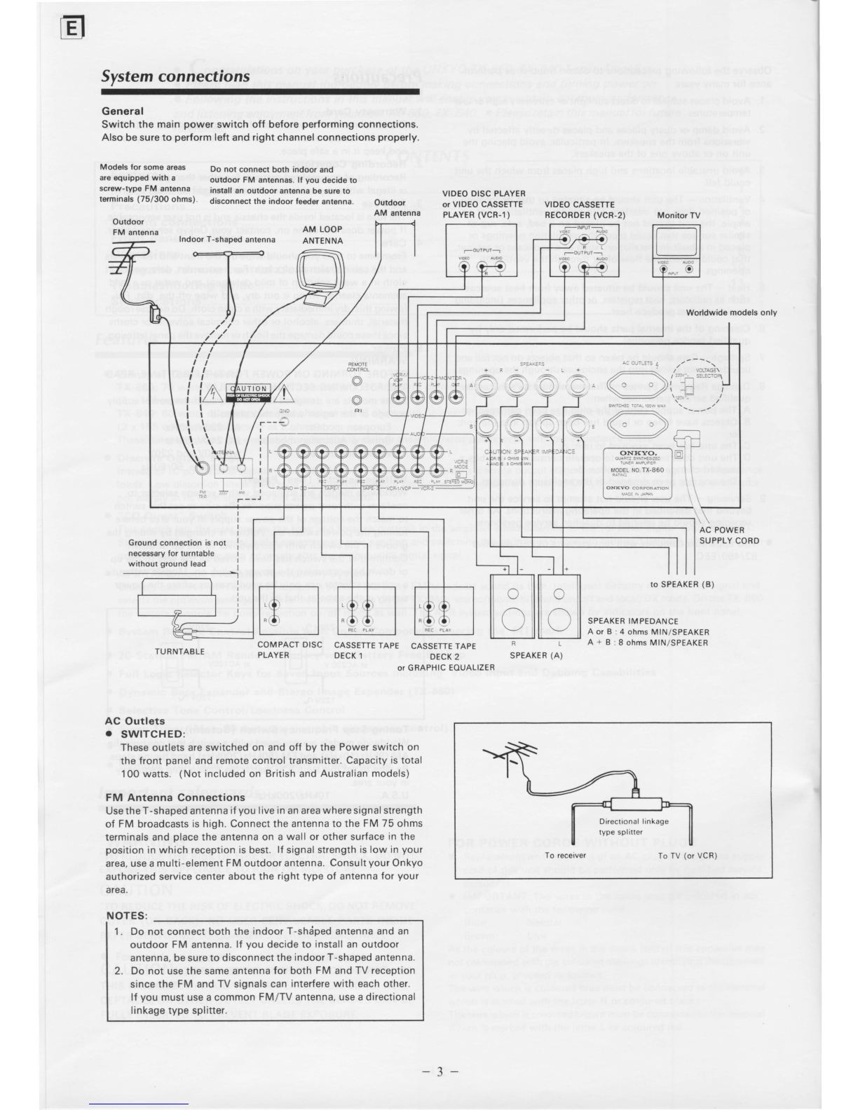
Tape Recording
1. Make
allconnectionsbetweenthetape
deckandtheunitas
shown
inthe
System
ConnectionsDiagram.
2. Radio:
Record:
CD:
Press
theFMor
AM Input
Selectorbutton
p].
Press
thePHONOInput
Selector
button
El.
PresstheCDlnput
Selector
button
p|.
4.
VCR-1/VDP:PresstheVCR-1/VDP
Input
Selectorbotton
@.
VCR-2: Press
the
VCR-2lnput
Selectorbutton
@.
Put the tape deck in the recordingmode.The recordingcan be
monitoredthrough the speakers
or headphones
asdesired. For
TAPE-2,
turn on the correspondingTapeMonitor button to hear
the signalthat. having been recorded,isreturned
from the deck
to the TX-860/840. (if the deck has
threeheads).
Setthe properrecordinglevel
usingthe controls on the tape
deck usedfor recording.Also, during recording
and dubbing
operations,
never
changethe positions
of any controls (bass,
treble,etc.)on this unit.
Tape-to-Tape Dubbing
1. Connect
the two tape decksto this unit asshown in the System
Connectionsdiagram.
2. Load
theoriginaltape
intapedeck1 and
the blanktape intape
deck2.
3. Press
theTAPE-1 lnput Selector
button pl.
4. Put
tapedeck1 in the playback
mode and
tapedeck2 in the
recording
mode.
5. The sourcesignalcan be monitored through the speakersor
headphones,when the TAPE-2 MONITOR button @ is in ttre
OFF
position. lf tapedeck
2 has
three
heads,
the
just-recorded
signalcan be monitored
(when the TAPE-2 MONITOR button
@ isin the ON position). Refer
to the tapedeck instruction
manuals
for moredetails.
Using the Graphic Equalizer
1. Connect
the graphic
equalizerto theTAPE-2
jacks
on the rear
panel.
2. lf a second
tapedeckisused,connect
it to the tape
jacks
on
thegraphic
equalizer.
3. Press
the TAPE-2 MONITOR button pl.
4. Follow
the graphic
equalizeroperating
instructions.
5. To record
an equalized
signal,usetapedeck 2 (connected
to
the equalizer)
for recording.
Video Disc Player Playback
1. Connectthe video
disc
player
to the TX-860/840 asshown in
the Systemconnectionsdiagram.
Thenconnecta monitoror
TV having
a vrdeoinput
jack
to the TX-860/840 video "MON-
ITOR
OUT"jack.
Press
theVCR-1/VDP lnput Selector
button @.
Switch on the monitor TV, and start playback
of the video drsc
player.
Thepicture
will besentto the monitorTV and sound
to the speakersconnectedto the TX-860/840.
Refer
to the video disc player
instructionmanualfor additional
information.
2.
3.
4.
Confirm
thatthe
CD
player
is
connected
to theCDinput
jacks
on
the
rear
panel.
Confirm
that the output leadsfrom the tape deck to the TAPE-1
andlor TAPE-2 jacks on the rear
panel.
Presetfrequencies
can be transferredto other channels.For
example,
the FM station storedon Presetbutton number 6 can
betransferredto Preset
button number1in
the
following manner:
1) PressPreset
button number 6.
2) Press
the Memory button [T0l lwtemory indicatorlights).
3) PressPreset
button number 1.
4) The samestation is now storedon both Preset
buttons 1
and
6.
Confirm that the turntable is connectedto the PHONO
jacks
on the rear
panel.
-9-