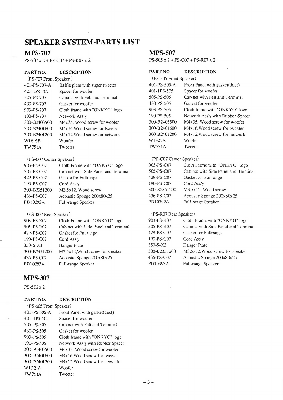
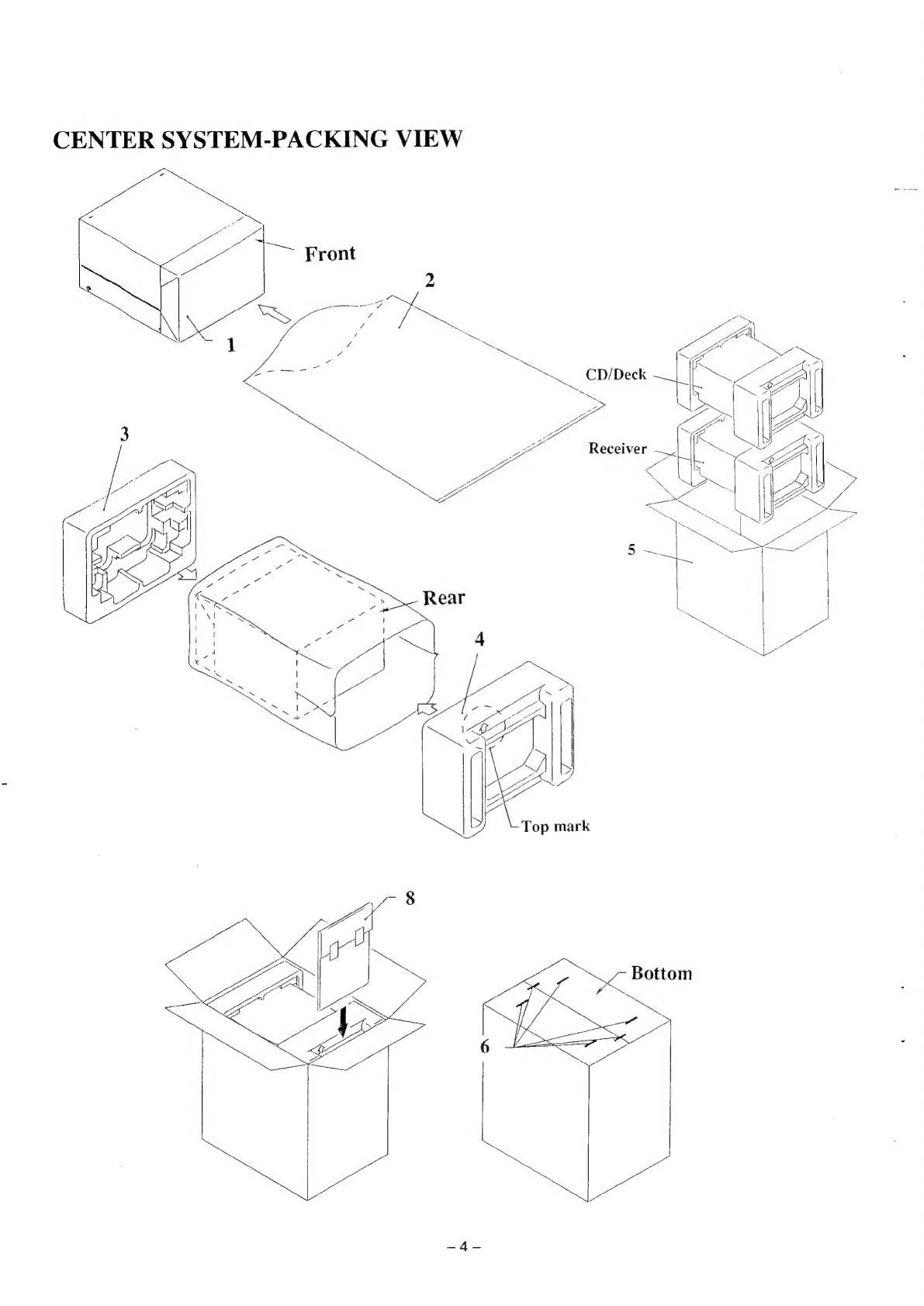
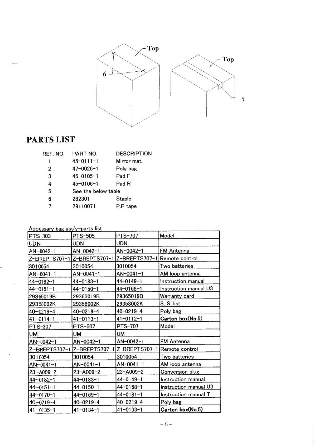
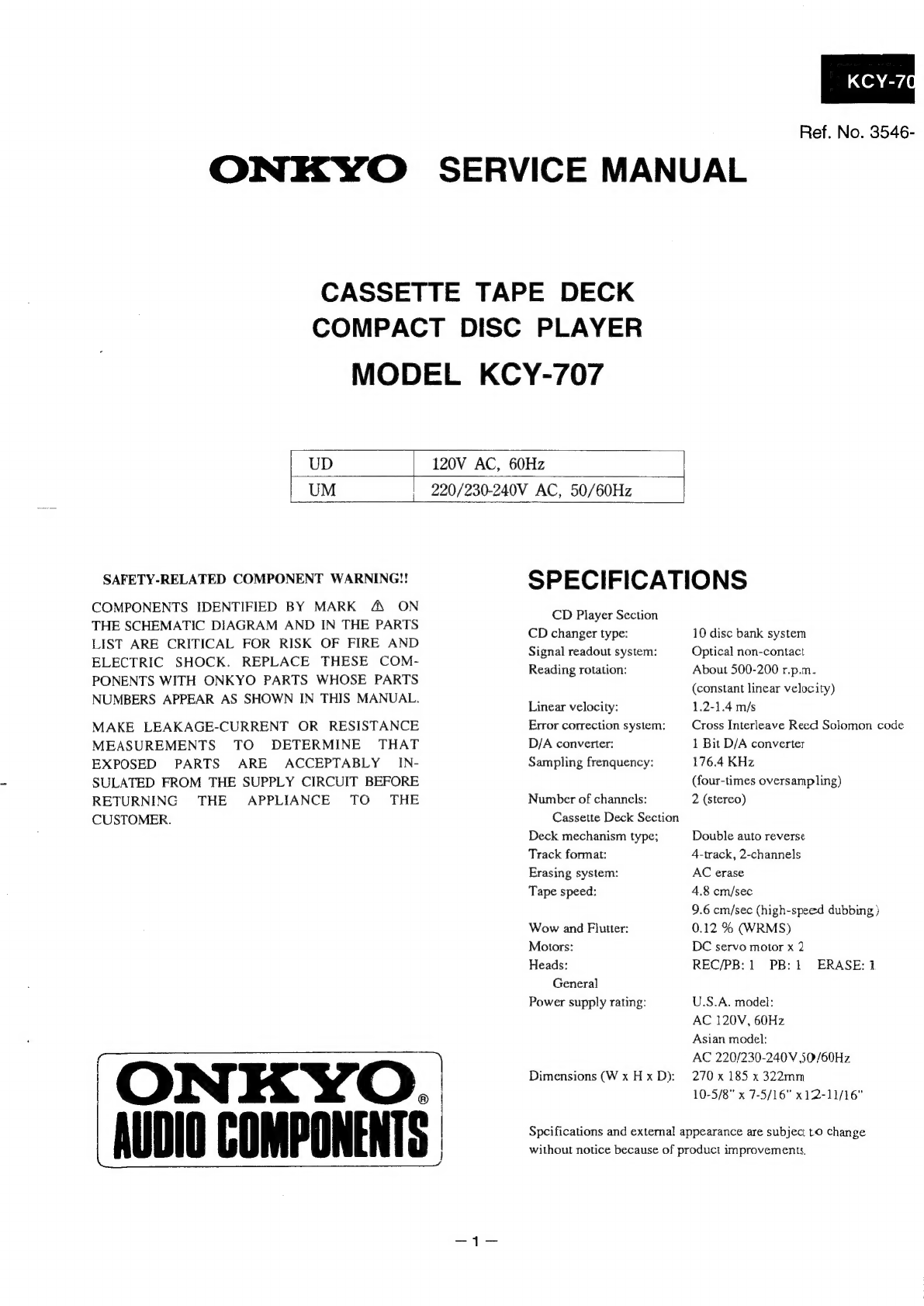
Onkyo PTS-707 User manual

Ref.
No.
3546
ONKYO.:
SERVICE
MANUAL
Personal
Theater
System
U.S.A.
Model
Asian
Model
PTS-707
PTS-707
PTS-505 PTS-507
PTS-303 PTS-307
Rix.
AUDIO
COMPONENTS
|

SPEAKER
SYSTEM
SPECIFICATIONS
MPS-707
Speakers
Front:
Type:
3-Way,
Bass
reflex,
Magnetism
sealed
type
Speakers
Woofer;
16cm
cone
type
Mod-range;
7cm
cone
type
Tweeter;
2cm
ceramic
type
Impedance:
8
Dimensions
195
X
370
X
295
mm
(W
XD
XH)
(7-11/16
X
14-9/16
X
11-5/8in.)
Center:
Type:
1-Way,
Full
range,
Magnetism
sealed
type
Speakers
10cm
cone
type
Impedance:
82
Dimensions
270
X
115X147
mm
(W
XD
XH)
(10-5/8
X
4-9/16
X
5-13/16in.)
Surround
Type:
1-Way,
Full
range
type
Speakers
10cm
cone
type
Impedance:
16
9
Dimensions
174X115
133
mm
(W
XD
XH)
(6-7/8
X
4-9/16
X5-1/4in.)
MPS-307
Speakers
Type:
2-Way,
Bass
reflex,
Magnetism
sealed
type
Speakers
Woofer;
13cm
cone
type
Twectcr;
5
cm
cone
type
Impedance:
82
Dimensions
185X370
X
295
mm
(W
XD
XH)
(7-5/16
X
14-9/16
X
11-5/8in.)
CONNECTION
DIAGRAM
PS-707
PIEZO
MPS-507
Speakers
Front:
Type:
Speakers
Impedance:
Dimensions
(W
XD
XH)
Center:
Type:
Speakers
Impedance:
Dimensions
(W
XD
XH)
Surround
Type:
Speakers
Impedance:
Dimensions
(W
XD
XH)
2-Way,
Bass
reflex,
Magnetism
scaled
type
Woofer;
13cm
cone
type
Tweeter;
5
cm
cone
type
80
185
X370
X
295
mm
(7-5/16
X
14-9/16
X
11-5/8in.)
1-Way,
Full
range,
Magnetism
sealed
type
10cm
cone
type
82
270
X
115
*
147
mm
(10-5/8
X
4-9/16
X
5-13/16in.)
1-Way,
Full
range
type
10cm
cone
type
16
174X115
X133
mm
(6-7/8
X
4-9/16
X5-1/4in.)
@ ©
a
WF
‘>
A
A
©
C1
3.3uF/100V
py
199
5w
=4
Oo
L1
0.82mH
TW
@

SPEAKER
SYSTEM-PARTS
LIST
MPS-707
PS-707
x
2
+
PS-CO7
+
PS-RO7
x
2
PARTNO.
DESCRIPTION
(PS-707
Front
Speaker
)
401-PS-707-A
401-1PS-707
505-PS-707
430-PS-707
903-PS-707
190-PS-707
300-B2403500
300-B2401600
300-B2401200
W1695B
TW751A
Baffle
plate
with
super
tweeter
Spacer
for
woofer
Cabinet
with
Felt
and
Terminal
Gasket
for
woofer
Cloth
frame
with
"ONKYO"
logo
Network
Ass'y
M4x35,
Wood
screw
for
woofer
M4x16,Wood
screw
for
tweeter
M4x12,Wood
screw
for
network
Woofer
Tweeter
(PS-CO7
Center
Speaker)
903-PS-CO7
505-PS-C07
429-PS-C07
190-PS-C07
300-B2351200
436-PS-C07
PD10392A
Cloth
Frame
with
"ONKYO"
logo
Cabinet
with
Side
Panel
and
Terminal
Gasket
for
Fullrange
Cord
Ass'y
M3.5x12,
Wood
screw
Acoustic
Sponge
200x80x25
Full-range
Speaker
(PS-RO7
Rear
Speaker)
903-PS-RO7
505-PS-RO7
429-PS-C07
190-PS-C07
350-S-X3
300-B
2351200
436-PS-CO7
PD10393A
MPS-307
PS-505
x
2
PARTNO.
Cloth
Frame
with
"ONKYO"
logo
Cabinet
with
Side
Panel
and
Terminal
Gasket
for
Fullrange
Cord
Ass'y
Hanger
Plate
M3.5x12,
Wood
screw
for
speaker
Acoustic
Sponge
200x80x25
Full-range
Speaker
DESCRIPTION
(PS
-505
Front
Speaker)
401-PS-505-A
401-1PS-505
505-PS-505
430-PS-505
903-PS-505
190-PS-505
300-B2403500
300-B2401600
300-B2401200
W1321A
TW751A
Front
Panel
with
gasket(duct)
Spacer
for
woofer
Cabinet
with
Felt
and
Terminal
Gasket
for
woofer
Cloth
frame
with
"ONKYO"
logo
Network
Ass'y
with
Rubber
Spacer
M4x35,
Wood
screw
for
woofer
M4x16,Wood
screw
for
twecter
M4x12,Wood
screw
for
network
Woofer
Tweeter
MPS-507
PS-505
x
2
+
PS-C07
+
PS-RO7
x
2
PART
NO.
DESCRIPTION
(PS-505
Front
Speaker)
401-PS-505-A
401-1PS-505
505-PS-505
430-PS-505
903-PS-505
190-PS-505
300-B2403500
300-B2401600
300-B2401200
W1321A
TW751A
Front
Panel
with
gasket(duct)
Spacer
for
woofer
Cabinet
with
Felt
and
Terminal
Gasket
for
woofer
Cloth
frame
with
"ONK
YO"
logo
Network
Ass'y
with
Rubber
Spacer
M4x35,
Wood
screw
for
woofer
M4x16,Wood
screw
for
tweeter
M4x12,Wood
screw
for
network
Woofer
Tweeter
(PS-C07
Center
Speaker)
903-PS-C07
505-PS-C07
429-PS-C07
190-PS-C07
300-B2351200
436-PS-C07
PD10392A
Cloth
Frame
with
"ONKYO"
logo
Cabinet
with
Side
Panel
and
Terminal
Gasket
for
Fullrange
Cord
Ass'y
M3.5x12,
Wood
screw
Acoustic
Sponge
200x80x25
Full-range
Speaker
(PS-RO7
Rear
Speaker)
903-PS-RO7
505-PS-RO7
429-PS-C07
190-PS-C0O7
350-S-X3
300-B
2351200
436-PS-C07
PD10393A
Cloth
Frame
with
"ONKYO"
logo
Cabinet
with
Side
Panel
and
Terminal
Gasket
for
Fullrange
Cord
Ass'y
Hanger
Plate
M3.5x12,Wood
screw
for
speaker
Acousuc
Sponge
200x80x25
Full-range
Speaker

CENTER
SYSTEM-PACKING
VIEW
sane

PARTS
LIST
REF.NO.
PART
NO.
DESCRIPTION
1
45-0111-1
Mirror
mat
2
47-0026-1
Poly
bag
3
45-0105-1
Pad
F
4
45-0106-1
Pad
R
5
See
the
below
table
6
282301
Staple
7
29110071
P.P
tape
Accessary
bag
ass'y—parts
list
PTs-303
—sPTS-505
=
|PTS-707__—S
[Model
UDN.
SS
UDN
CSUN
|
AN-0042-1____
|AN-0042~1
010054
__
Two
batteries
AN-0041-1
AN-0041-1
4-—0182-1
nstruction
manual
4-0151-1
44-0150-1
44-0168-1
2
2
2
9365019B 9365019B
9358002K
S.
S.
list
40-0219-4_
41-0114-1
41-0113-1__—([41-0112-1
PTS-307
Ipts-507___——s«([PTS-707__———
[Model
—
Cd
U
P
UM
UMC
AN-0042-1
—BREPTS707-1
Remote
control
01.0054
Cc
N
3
T
0041-1
AN-0041-1
AN-0041-1
23—A009-2
23-A009-2
23-A009-2
Gonversion-plus
44-0183-1
44-0149-1
>
oo
z
>
"
2
co
Ro
_
4—0151-1
4170-1
44-0181-1
0-0219-4
1~-0135-1
Carton
box(No.5)

PACKING
VIEW
MPS-707
PARTS
LIST
REF.NO.
PART
NO.
DESCRIPTION
]
404-PSCRO7
Pad
(Top
and
Bottom)
2
402-PS-C07
450x280,
Poly
bag
3
402-PS-RO7
360x280,Poly
bag
4
404-PS-707
Pad
(Top
and
Bottom)
5
402-PS-707
710x520,Poly
bag
6
617-MPS-707
Speaker
cord
Ass'y
6
300-022095
Wood
screw
7
600-MPS-707
Carton
box
8
29110071
PP
tape

PACKING
VIEW
MPS-507
PARTS
LIST
REF.NO.
PART
NO.
DESCRIPTION
1
404-PSCRO7
Pad
(Top
and
Bottom)
2
402-PS-C07
450x280,
Poly
bag
3
402-PS-RO7
360x280,Poly
bag
4
404-PS-505
Pad
(Top
and
Bottom)
5
402-PS-707
710x520,Poly
bag
6
617-MPS-707
Speaker
cord
Ass'y
6
300-022095
Wood
screw
7
600-MPS-505
Carton
box
8
29110071
PP
tape

PACKING
VIEW
MPS-307
PARTS
LIST
REF.NO.
PART
NO.
DESCRIPTION
1
402-PS-707
710x520,Poly
bag
2
404-PS-505
Pad
(Top
and
Bottom)
3
617-SS-D555
Speaker
cord
Ass'y
4
600-MPS-303
Carton
box
5
29110071
PP
tape
SYSTEM
COMPONENTS
|
_|Model_|Receiver
[CD/Tape
_|Front Speaker |Center
Speaker
[Rear
Speaker|
scoot
{
won
|
ny-208
f
xer-ta?
|_es-s05_}_———_}_—__—__
UDN
UDN
pts-307
|
um
|
ry-307
|
key-707|
ps-sos
[|
|
pts-507
|
_um_|
ry-s07
|
Kcy-707|
ps-50s__|
ps-co7__|
Pps-so7_|
Ipts-707
|
UM
|
RY-707
PS-707
PS-CO7
PN.
0M3546
NS608
Printed
in
Japan

KCY-70
Ref.
No.
3546-
ONKYO
SERVICE
MANUAL
CASSETTE
TAPE
DECK
COMPACT
DISC
PLAYER
MODEL
KCY-707
UD
120V
AC,
60Hz
UM
220/230-240V
AC,
50/60Hz
SAFETY-RELATED
COMPONENT
WARNING!!
COMPONENTS
IDENTIFIED
BY
MARK
A
ON
THE
SCHEMATIC
DIAGRAM
AND
IN
THE
PARTS
LIST
ARE
CRITICAL
FOR
RISK
OF
FIRE
AND
ELECTRIC
SHOCK.
REPLACE
THESE
COM-
PONENTS
WITH
ONKYO
PARTS
WHOSE
PARTS
NUMBERS
APPEAR
AS
SHOWN
IN
THIS
MANUAL.
MAKE
LEAKAGE-CURRENT
OR
RESISTANCE
MEASUREMENTS
TO
DETERMINE
THAT
EXPOSED
PARTS
ARE
ACCEPTABLY
_IN-
SULATED
FROM
THE
SUPPLY
CIRCUIT
BEFORE
RETURNING
THE
APPLIANCE
TO
-
THE
CUSTOMER.
AUDIO
COMPONENTS
SPECIFICATIONS
CD
Player
Section
CD
changer
type:
Signal
readout
system:
Reading
rotation:
Linear
velocity:
Error
correction
system:
D/A
converter:
Sampling
frenquency:
Number
of
channels:
Cassette
Deck
Section
Deck
mechanism
type;
Track
format:
Erasing
system:
Tape
speed:
Wow
and
Flutter:
Motors:
Heads:
General
Power
supply
rating:
Dimensions
(W
x
H
x
D):
10
disc
bank
system
Optical
non-contact
About
500-200
r.p.m.
(constant
linear
velocity)
1.2-1.4
m/s
Cross
Interleave
Reed
Solomon
code
1
Bit
D/A
converter
176.4
KHz
(four-times
oversampling)
2
(stereo)
Double
auto
reverse
4-track,
2-channels
AC
erase
4.8
cm/sec
9.6
cm/sec
(high-speed
dubbing
}
0.12
%
(WRMS)
DC
servo
motor
x
2
REC/PB:
1
PB:
1
ERASE:
U.S.A.
model:
AC
120V,
60Hz
Asian
model:
AC
220/230-240V
50/60Hz
270
x
185
x
322mm
10-5/8"
x
7-5/16"
x12-11/16"
Spcifications
and
external
appearance
are
subject
to
change
without
notice
because
of
product
improvements,

KCY-707
TABLE
OF
CONTENS
Specification
1
Caution
on
replacement
of
optical
pickup
2
Protenction
of
eyes
from
laser
beam
during
servicing
3
Laser
warning
labels
3
Adjustment
procedures
4
Microprocessor
terminal
description
6
IC
block
diagrams
7
Chassis-exploded
view
13
Parts
list
(chassis)
14
Cassette
tape
dack
mechanism-exploded
view
15
Parts
list
(deck
mechanism)
17
CD
mechanism-exploded
view
18
Parts
list
(CD
mechanism)
19
Printed
circuit
board
parts
list
20
Block
diagram
21
Printed
circuit
board
view
from
bottom
side
23
Schematic
diagram
27
CAUTION
ON
REPLACEMENT
OF
OPTIONAL
PICKUP
The
laser
diode
in
the
optical
pickup
block
is
so
During
repair,carefulley
take
the
following
precautions.
sensitive
to
static
électricity,surge
current
and
etc,
(The
following
precautions
are
included
in
the
service
that
the
components
are
liable
to
be
broken
down
parts.)
or
its
reliability
remarkably
deteriorated.
PRECAUTIONS
1.Ground
for
the
work-desk.
3.Grounding
for
the
human
body.
Place
a
conductive
sheet
such
as
a
sheet
of
copper
Be
sure
to
put
on
a
wrist-strap
for
grounding
whose
(with
inpedance
lower
than
10M.)
on
the
work-
other
end
is
grounded.
desk
and
place
the
set
on
the
conductive
sheet
so
Be
particularly
careful
when
the
workers
wear
that
the
chassis.
synthetic
fiber
clothes,
or
air
is
dry.
2.Grounding
for
the
test
equipment
and
tools.
4
Select
a
soldering
iron
that
permits
no
leakage
and
Test
equipments
and
toolings
should
be
grounded
have
the
tip
of
the
iron
well-grounded.
in
order
that
their
ground
level
is
the
same
the
5.Do
not
check
the
laser
diode
terminals
with
the
ground
of
the
power
source.
probe
of
a
circuit
tester
or
oscilloscope.

PROTECTION
OF
EYES
FROM
LASER
BEAM
DURING
SERVICING
This
set
employs
a
laser.
Therefore,
be
sure
to
follow
carefully
the
instructions
below
when
servicing.
WHEN
SERVICING,
DO
NOT
APPROACH
THE
LASER
WARNING!!
Laser
EXIT
WITH
THE
EYE
TOO
CLOSELY.
IN
CASE
IT
IS
*
NECESSARY
TO
CONFIRM
LASER
BEAM
EMMISION,
BE
SURE
TO
OBSERVE
FROM
A
DISTANCE
OF
MORE
THAN
30cm
FROM
THE
SURFACE
OF
THE
OBJECTIVE
LENS
ON
THE
OPTICAL
PICK-UP
BLOCK.
LASER
WARNING
LABELS
The
label
shown
below
are
affixed.
1.
Warning
lable
2.
Class
|
label
DANGER.Iwuisiate
LASER
RADIATION
EN
OPEN
AND
INTERLOCK
FAILED
OR
DEFEATED.
WHEN
OP
AVOID
DIRECT
EXPOSURE
TO
BEAM.
CAUTION.
Hazarpous
Laser
AND
ELECTROMAGNETIC
RADIATION
WHEN
OPEN
AND
INTERLOCK
DEFEATED.
ATTENTION.navonnement
LASER
ET
ELECTROMAGNETIQUE
DANGEREUX
SI
OUVERT
AVEC
L'ECLENCHEMENT
DE
SECURITE
ANNULE.
LUOKAN
1
“CLASS
1
LASER
LASERLAITE
PRODUCT”
KLASS
1
LASER
APPARAT
ADVARSEL
Laser
Diode
Properties
e
Material:
GaAS/GaAlAs
@
Wavelength:
780nm
@
Emission
Duration:
continuous
e
output:
max.
0.5mW*
This
output
is
the
value
measured
at
a
distance
about
1.8mm
from
the
objective
lens
surface
on
the
Optical
Pick-up
Block.
Denna
maekning
er
anbragt
pa
apparatets
hojre
side
og
indikerer,
at
apparatet
arbejder
med
laserstraler
af
klasse
1,
hvilket
betyder,
at
der
anvendes
taserstraler
af
svageste
klasse,
og
at
man
ikke
pa
apparatets
yderside
kan
blive
udsat
for
utilladelig
kraftig
straling.
APPARATET
B@/R
KUN
ABNES
AF
FAGFOLK
MED
SE
RLIGT
KENOSKAB
TIL
APPARATER
MED
LASERSTRALERI
Indvendigt
i
apparatet
er
anbragt
den
her
gengivne
advarselsmérkning,
som
advarer
imod
at
foretage
sddnne
indgreb
i
apparatet,
at
man
kan
komme
til
at
udsaette
sig
for
laserstraling.
VAROITUS!
LAITTEEN
KAYTTAMINEN
MUULLA
KUIN
TASSA
KAYTTOOHJEESSA
MAINTULLA
TAVALLA
SAATTAA
ALTISTAA
KAYTTAJAN
TURVALLISUUSLUOKAN
1
YLITTAVALLE
NAKYMATTOMALLE
LASERSATEILYLLE

,JSTMENT
PROCEDURES
FOR
CASSETTE
TAPE
DECK
PRECAUTION
TEST
EQUIPMENT
/
TOOL
REQUIRED
1.
Before
adjustment,
clean
the
following
parts
Audio
osccilator
a
with
an
alchol
moistend
swab.
Digiyal
frequency
counter
*record/playback
head
*erase
head
Oscilloscope
*pinch
roller
*capstan
Attenuater
AC
voltmeter
;
2.
Do
not
use
magnetized
screwdriver
for
adjustment.
Non-magnetic
screwdriver
Test
tapes
3
.
Demagnetized
record/plaiback
head
with
TCC-153
:
10kHz,
-10dB
a
liead
demagnetizer.
MTT-111N
—
:
3kHz,
-10dB
MTT-150
:
Dolby
level
calibration
400Hz,
tone
200nWb/m
Connection
of
ae
Output
Adjustment
:
fal
tea
|
ene
Line
input
Test
tape
|
Mode
a
dicatise
point
Adjust
Remarks
requency
Tape
counter
to
iy
Frequency
|Nomal
Speed
]3,000
to
1\speed
|
TP1,2
output
MTT-111N
counter
|VR809,811
|3030Hz
terminal
High
Speed
6,000
to
VR810,812
6060Hz
AC
voltmeter
Head
and
oscilloscope
AC
2
|azimuth
[to
TP1,2
output
TCC-153
voltmeter
terminal
A
DECK
AC
voltmeter
VR803
(L
ch)
to
terminals
AC
VR804
(R
ch)
TPI
(L)
MTT-150
|
PB
lvoluneter
|B
DECK
TP2
(R)
VR806
(L
ch)
VR805
(R
ch)
Frequency
METAL
Frequency
TAPE
REC
[counter
L803
85KHz
counter
to
erase
head
lead
loose
coupling
NORMAL
|
REC/
|AC
VR802
(L
ch)
kHz
&
12kH2z
bra
pe
VR801
(R
ch)
NORMAL
REC
AC
Attenutor
or
245mV
TP3
(L
ch)
TAPE
voltmeter
|AF
OSC
output
|(-10dBm)
TP4
(R
ch)
REC/
{AC
VR807
(Lch)
|Same
level
at
|TP1
(L
ch)
PB
{voltmeter
|VR808(R
ch)
|REC/PB
TP2
(R
ch)
Maximum
level
&
same
phase
at
channels
Head
azimuth
screw
AC
voltmeter
to
TP1,2
output
terminal
at
REC/PB
Blank
tapes
NORMAL:
:
:UD-1
C-90
PLAY
torque::**'*
30~70g/em
HIGH:
++:
XL-II
C-90
FF.REW
torque:
+
+
:80~170g/cm
METAL:
::
:
XS
C-90
Back
tension’:
+++"
2~6g/em
Oscilloscope
0°
(IN
PHASE)
45° 90°
180°
1)
Fig.1
Confirming
phase
relationship
Fig.
2

KCY-70
ADJUSTMENT
PROCEDURES
FOR
COMPACT
DISC
PLAYER
E-F
BALANCE
ADJUSTMENT
PROCEDURE:
802
D0
SV
ON
Be
ot
Connect
oscilloscope
to
the
test
points
TE
and
Vref.
Press
and
hold
down
the
SUPER
DUBBING
button,then
press
the
POWER
button.
Press
FUNCTION
CD
button
for
4
seconds
or
more.
(CD
section
is
TEST
MODE.)
Put
the
disc
(YEDS-18)
in
and
press
PLAY
button.
Press
the
MEMORY
button.
(Tracking
servo
is
OFF.)
Adjust
VR701
so
that
the
traverse
waveform
becomes
symmetrical
above
and
below.
Press
the
MEMORY
button.
(Tracking
servo
is
ON.)
Press
the
STOP
button.
Turn
POWER
switch
off.
li)
f
Hl
NAAN
&
Ht
A=B
Wi
|
|
|
Ii
WY)
H
ae
|__4
VOLT/DIV:
0.5V
TIME/DIV:
1ImSEC
FOCUS
BIAS
ADJUSTMENT
PROCEDURE:
1.
2.
Turn
POWER
switch
on.
3.
4,
Adjust
VR702
for
an
optimum
waveform
eye
pattern
or
so
that
the
peak
is
maximum.
Connect
osilloscope
to
test
points
RF
anf
GND.
Put
disc
(YEDS-18)
in
and
press
PLAY
button.
Optimum
eye
pattern
means
that
shape
"<>"
can
be
clearly
distinguished
at
the
center
of
the
waveform.
RF
signal
waveform
Remarks:
When
adjusting,
set
the
oscilloscope
AC
rang
and
raise
its
vertical
sensitivity
so
that
the
eye
pattern
can
easily
be
seen.

KCY-707
wstueyaul
JosueYyo
(]D
JOj
oNUED
INOW]
CO
|
aSB9
OSIp
JO}
UONIIIap
uOTsod
azipentUy
|
I
|
aSk89
OSIp
Jo
uoNtsod
1oj
indut
Josuasg
08
6L
8L LL
9L
CL
tL
DI
Nod
paiuaixe
01
indino
Yop
|
oO
|
Wiods}
8c
mjon
somsepyl
-
|
_
PIV]
ie
|
sauanue
Gy
aj
wapanow]
|
SAV]
96
|
pasn
ion]
I
¢
pasn
ion]
-
SNIATH
indut
xujeut
Aay
[ddns
samog
eh
|
“1OJBUOSAI
OIUB1I9
ZHI’
8
B41
2aUUOD
eae
IvLx|
ze
|
€NIAaM
is
ES
=:
|
YOO[D
Ula1SA$
JO]
[BUTULID]
UOT]DSUUOD
JO}RUOSOY
it
|
IW.LXd
|
ole
|
OIO
Tossao01do191U
qns
Joy
mndut
say
re
‘Lasau
0
V
29p
10j
[oNUOD
paads
Iolo]
|
Oo
|
WLVC-V
62
V
Y92P
JO}
[ONUODS
[109
plous[og
|
Oo
|
10S-V
8Z
OL
yndut
xuyeur
Ko
a}
I
315
Ooln
<
\o
co]
Z|
Z/Z
PAL
tabled
a
ALSIS
IRS]
6]
JESS
Sala
poy
|
Go
|
fg}
oy} oy]
SY]
|
oa] ca]
oa]
a]
et]
|
{aM
|MIMIM/>
[2
[MIMI
MIM[DOLS
™
ae
¥
x00p
Joy
indut
youms
uoneiodol
|
|
MSAGOW-V]
LZ
zsaa]_
99s
V
3029p
Joy
indur
uonoaiap
ystuy
adep]
]
|
GNa-v]
9%
‘loyeotpul
uotesado
Jo]
indino
[eusts
ued
tsaaT]
69
|
V
3002p
Joy
ade}
onasseo
soy
nduruondaiaq]
[|
LSd-¥[
SZ
Surpeo[
Joy
indui
uorsa1ap
UOTITsoq
MS-avOl|
9
|
V
sep
Joy
indut
youms
uonesodo]
y
|
MSAGOW-A|
+z
|
JossadoidorIotul
UTeU
WoL
mdut
jsanbar
Jaysue
ly,
lows!
€9
|
¥
oop
Joy
indur
wor
Sut
rt
|
ana-af
ez
JOSSISOIGOIONUL
UTR
LU
OF
INAINO
JsonDal
Iajsuel]
q
YOep
oj
adevi
anassed
10}
Indut
uot9919q
ae
LSd-d
eee
oll
Oo
a
n
co
areid
Surpeoy
jo
uontsod
soy
indur
sosuas
uoNa10q
Tas-avo7|
19
|
{
UO!
v-dua|
Iz
|
uado
Aes}
Joy
indur
yoiiMs
uoNsa1a¢]
NdO-AML
|
609
|
ade}
anassed
JO
g
apts
ay]
Joy
Indur
uoNdalap
UONUDADIg
ne
a-dua
|
0c
|
A9ep
oJ
Jon1uos
[foo
prousjos|
O
|
=TOS-al
6l
|
|
LN]
8T
|
ad/ae]
Lt
|
ALAW-Oaa]
Ot
|
Sia]
st
|
asad]
vl
uiganp
peads
aiqanq]
O
|
daads-IH|__¢1__|
YOIA
Jo
[Busts
olpne
Joy
[omUOS
Suny
rO
|
aLAW-T]
2
|
O1dSd.
dp
o1mdno
yoojo
peared?
O
|
AIDOs|_
Is
_
feudis
Sums
Suiqqnd]
O
|
ONT#sAd|
1
__|
Josssooidoso1ur
urews
01
indino
eusis
eIep
sayjsuez_]
O
|
LAOS]
OS
fous
FAO/NO
Aqioqd;
oO
| =
AdTOd]
ol
sosssoo1dosorr
ureur
woody
indur
[eusis
erep
raysuesy
|
y
|
NI-
6b
Pop
st
ONT
JOSSIOOIMOIONU
UlBU
WO
INGUT
[RUBIS
YOO]D
JajsueL],
|
1
|
WTO
SP
Uld
INdUI
SUTT9S
SpOUl
sap
uonsas
(a
soy
induriesoy!
QO
|
LSuxd
Ly
oss]
9p
QI
oases
Ga
o1indino
ereq]
O
|
Sr
DI
oases
G-D
ovindino
yore
erg]
O
|
LTXG9|
vb
Oy
oars
GD
o1ndino
xo[D]_-O
|
MING]
rests
ch
J
Mod
papualxs
0}
Indino
ajqeua
Iv
WSIUBYIoU!
JasueYyd
CD
JOJ
[ONUOD
JOIOy
|
O
|
NOWdIaOsad]
O/1
‘ON
NId
NOLLd1YOSaa|
O/T
[|
‘TOMIWAS]
“ON
Nid
|
NOILdIMDS3G
IWNINWYAL
YOSSADOYdOYOIIN
6¢
8s
pron
asopo
Abt)
JOF
Indur
yoiims
UONIA10¢]
|
1
|
LS
“9S12ARQ
JO
UOTRIado
i
T
UOT
x
96
“aSi9Ael]
JO
UOeIado
Umop
Jo
Ystuy
Joj
Indu
uonseiaq/
T
|
NMC-AML;
ss
|
CD
Jo
azis
10j
ndutuonsaieqg]/
T
|
NAS-OSIG]
¢s
|
Srasd
ao
way
UTA
eeG|
1
WSos|_—_cs
nN
=
i}
als)
EIZ|2
a
f=]
wu
°
=
a
i=}
wa
be
&
3
a
=
&
S
3)
&
oO
a
a
-
>
~
e
2)
LSAL
TTHSAV
CTASNV
wAMOd-d)d
ALAW-d)
Odd
”
rep
[euBis
anasseo
10
Gd
oj
uid
Jo1a[9s
nding
WIND
(Jd
10]
JONuOS
Ayddns
Jamog
(D
Jo
[eusis
o1pne
Ioj
joNUOS
SUTIN
UISIUBYIUI
JoZUeYD
(JD
JO}
JONUOD
JasuN]q
mlO
:
iS)
eee
<<
il
<
Q
1S)
ate)
ne
Ol
ZO
I
1S)
dOXd
"TOUWAS

IC
BLOCK
DIAGRAMS
IC701
CXA1782BQ
el
IL
DATA
REGISTER
eiNPUT
SHIFT
REGISTER
eADRESS.
DECODER
*OUTPUT
DECODER
su
&
TZC
COMP
8
Ly
NAAN
eal:
/\
Togi-3
FSt-4
TGi-2
TWI-7.PS1-4
me
=
os
a
TG1
O
FCS
PHASE
COMPENSATION
FS
1
O
jot
S
©
OFCT
=
rm
o—O
A
*WINDOW
COMP.
Oo
O
:
pg

KCY-707
1C702
CXD2508AQ
error
corrector
Interface
Digital
Filter
+
1bit
DAC
Lees
Lees
{16K
RAM
EFM
demodulator
asymmetry
corrector
SUB
code
Processor
digital
CLV
CPU
interface
Servo
auto
sequencer
DOUT

1C704
BA6398FP
D.BUF
:
Drive
Buffer
IC705
BA6247

AMS
OUT
AMS
NF
AMS
LPF
GND
REC EVR
L
PB
EVR
AL
23]
B1AS
2T/AMS
T
ISJEVR
REF
ag
28
--})9)PB
EVR
BL
“HE
7/PB
EVR
AR
a5
--{18]PB
EVR
BR
YSTEM
CONTROL
AS
(WOZL/MOL)
D3
a
AS
W1an[
S|
PBL
OUT|52
N.C.
ALC
R
IN(56
PBR
OUTIS3
ALC
LIN
1C802
BA3442BKS
Nm
i=)
rr
>
O
x<

1C803
CXA1101P
REC//PB
Bie
C14
#
var
PB
IN
o——9-
(——
LINE
OUT
Bees
7
€———o
REC
OUT
C11
C15
Vy
AT
u
eh
C25
4
4.7
REC
IN
o——9
Les
REC
Out
naa
C22
4€——-
LINE
OUT
C24
4
|
:
ae
ATT
:
Attenuator
Vec
ON
/
OFF
SC
:
Side
Chain
DET
:
Detector
IC605
BU4052BC
Vpp
16
INH
6
A
10
CONVER-~
B
TER
LEVEL
BINARY
TO
1
OF
4
DECODER
WITH
INHIBIT
Vss
VEE

CY-707
IC606
BU2092F
1C801
»
PC1330HA
SWri
GND
SWp,
CONT
GND
Vee
SWee
GND
SWr2
This manual suits for next models
4
Other Onkyo Home Theater System manuals

Onkyo
Onkyo HT-S5305 Specification sheet

Onkyo
Onkyo HT-SP904 Specification sheet

Onkyo
Onkyo HT-S5100 User manual

Onkyo
Onkyo HT-S790(B)/(S) User manual

Onkyo
Onkyo HT-S3800 User manual

Onkyo
Onkyo HTS5300B User manual

Onkyo
Onkyo PTS-507 User manual

Onkyo
Onkyo S680 - HT Home Theater System User manual

Onkyo
Onkyo HT-S4505 User manual

Onkyo
Onkyo HTP-530 User manual

Onkyo
Onkyo HT-S790 User manual

Onkyo
Onkyo HT-R960 User manual

Onkyo
Onkyo HT-S3100 User manual

Onkyo
Onkyo HT-S8400 Specification sheet

Onkyo
Onkyo HT-S3910 User manual

Onkyo
Onkyo HT-S5910 User manual

Onkyo
Onkyo HT-S8230(S) User manual

Onkyo
Onkyo HT-S894(B) User manual

Onkyo
Onkyo AVX-760LD User manual

Onkyo
Onkyo HTP-980 User manual