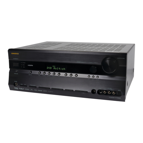
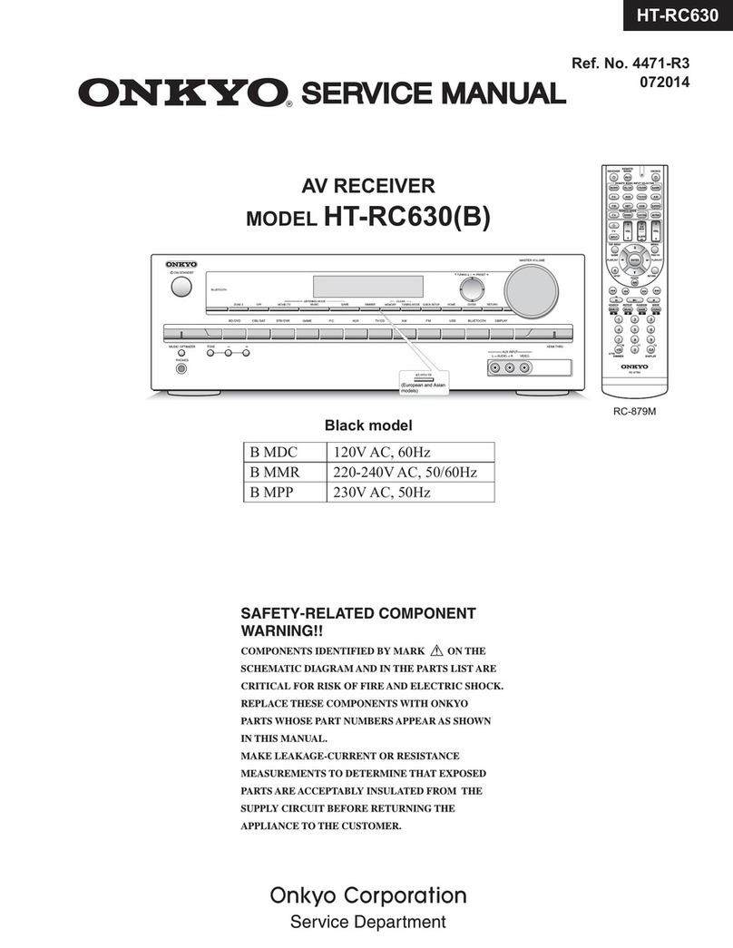
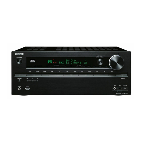
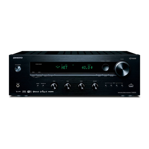
Onkyo TX-DS575X User manual

TX-DS575X
Ref.
No.
3648
062000
ONKYO,
SERVICE
MANUAL
AUDIO
VIDEO
CONTROL
RECEIVER
MODEL
TX-DS575X
Black
and
Silver
and
Golden
models
-BMDD
120V
AC,
60
Hz
|
_
BMPP/BMPT/
BMPA
ise
Seienrin
ne
_
SMPP.’GMPT
=
eee
BMWT/
BMWR/GMWT
220-230
V/120
V
A
3
|
GMwR
|
oe
C,
50/60
Hz
-GMGT
22
V
AC,
50,/60
Hz
SAFETY-RELATED
COMPONENT
WARNING!!
COMPONENTS
IDENTIFIED
BY
MARK
A
ON
THE
SCHEMATIC
DIAGRAM
AND
IN
THE
PARTS
LIST
ARE
CRITICAL
FOR
RISK
OF
FIRE
AND
ELECTRIC
SHOCK.
REPLACE
THESE
COM-
PONENTS
WITH
ONKYO
PARTS
WHOSE
PARTS
NUMBERS
APPEAR
AS
SHOWN
IN
THIS
MANUAL.
MAKE
LEAKAGE-CURRENT
OR
RESISTANCE
MEASUREMENTS
TO
DETERMINE
THAT
EXPOSED
PARTS
ARE
ACCEPTABLY
_IN-
SULATED
FROM
THE
SUPPLY
CIRCUIT
BEFORE
RETURNING
THE
APPLIANCE
TO
THE
CUSTOMER.
ONKYO.
AUDIO
COMPONENTS

SPECIFICATIONS
AMPLIFIER
SECTION
Continuous
Average
Power
output
(FTC)
All
channels:
Continuous
Power
output
(DIN)
Maximum
Power
output
(EIAJ)
Total
Harmonic
Distortion
IM
Distortion:
Damping
Factor:
Input
Sensitivity
and
Impedance
PHONO:
LINE
(CD.
TAPE,
DVD.
VIDEO
1,
2,
3):
MULTICHANNEL
INPUT
(FRONT
L/R,
SUR-
ROUND
L/R,
CENTER):
(SUBWOOFER):
COAXIAL
1,2
(DIGITAL)
Output
Level
and
Impedance
Rec
out
(TAPE,
VIDEO
1):
Pre
out
(SUBWOOFER).
Phono
Overload
Frequency
Response:
RIAA
Deviation:
Tone
Control
Bass:
Treble:
Signal-to-Noise
Ratio
Phono:
CD/Tape:
VIDEO
SECTION
Input
sensitivity/Impedance
(DVD,
VIDEO
1,
2,
3)
VIDEO
(Composite)
S-VIDEO
(Y
signal):
S-VIDEO
(C
signal):
Output
Level/Impedance
(VIDEO
1,
MONITOR)
VIDEO
(Composite):
S-VIDEO
(Y
signal)
S-VIDEO
(C
signal):
TUNER
SECTION
FM
Tuning
Range:
Usable
Sensitivity
Mono:
Stereo:
50
dB
Quieting
Sensitivity
Mono:
Stereo:
Capture
Ratio
Image
Rejection
Ratio
U.S.A.
&
Canadian
models
Other
area
models:
70
watts
per
channel
min.
RMS
at
8
ohms,
2
channels
driven
from
20
Hz
to
20
kHz
with
no
more
than
0.08%
total
harmonic
distortion.
90
watts
min.
RMS
at
6
ohms,
2
chai
nels
driven
from
1kHz
with
no
more
than
0.1%
total
harmonic
distortion.
100
watts
x
5
at
6
ohms
130
watts
5
at
6
ohms
0.08%
at
rated
power
(Front)
0.08%
at
rated
power
(Front)
60
at
8
ohms
(Front)
2.5
mV.
50
kohms
300
mV,
50
kohms
300
mY,
50
kohms
53
mV,
50
kohms
0.5
Vp-p.
75
ohms
300
mV,
2.2
kohms
1
V,
2.2
kohms
70
mV
RMS
at
|
kHz,
0.5%
T.H.D.
5
Hz
to
100
kHz,
+1dB,
~3dB
20
Hz
to
20
kHz, +0.8
dB
+10
dB
at
100
Hz
+10
dB
at
10
kHz
80
dB
(IHF
A.
5
mV
input)
100
dB
(IHF
A)
1
Vp-p.
75
ohms
|
Vp-p/75
ohms
0.28
Vp-p/75
ohms
1
Vp-p.
75
ohms
1
Vp-p/75.
ohms
0.28
Vp-p/75
ohms,
87.5
—
108.0
MHz
11.2
dBE,
1.0
pV
(75
ohms)
17.2
dBF.
2.0
py
(75
ohms)
17.2
dBf.
2.0
BV
(75
ohms)
37.2 dBf,
20
BV
(75
ohms)
2.0dB
40
dB
85dB
IF
Rejection
Ratio:
Signal-to-Noise
Ratio
Mono:
Stereo:
Alternate
Channel
Attenuation:
Selectivity:
AM
Suppression
Ratio:
Total
Harmonic
Distortion
Mono:
Stereo:
Frequency
Response:
Stereo
Separation
AM
Tuning
Range
U.S.A.
&
Canadian
models:
European
&
Australian
models:
Worldwide
models
Usable
Sensitivity
Image
Rejection
Ratio
IF
Rejection
Ratio:
Signal-to-Noise
Ratio:
Total
Harmonic
Distortion:
GENERAL
Power
Supply:
Power
Consumption:
Dimensions
(W
x
H
x
Dy:
Weight:
REMOTE
CONTROL
Transmitter
Signal
range
Power
supply:
90
dB
76
dB
70
dB
55.dB
50
dB
(DIN)
50dB
0.2%
0.3%
30
Hz
—
15
kHz.
+1.0dB
45
dB
at
|
KHz,
30
dB
at
100
Hz
—
10
kHz
530—1,710
kHz
(10 kHz
steps)
522—1,611
kHz
(9
kHz
steps)
531~1,602
kHz
(9
kHz
steps),
530—1,710
kHz
(10
kHz
steps)
30
pV
40
dB
40
dB
40
dB
0.7%
AC
120
V,
60
Hz
AC
230
V.
50
Hz
AC
220-230
V
and
120
V
switchable.
50/60
Hz
AC
220
V,
50/60
Hz
435
x
175
x
390
mm
17-1/8"
x
6-7/8"
x
15-3/8"
12.5
kg.
27.6
Ibs.
(AC
120
V,
60
Hz
model)
13.2
kg.
29.1
Ibs.
(other
models)
Infrared
Approx.
5
meters.
16
fi
Two
“AA”
batteries
(1.5
V
X
2)
Specications
and
features
are
subject
to
change
without
notice
Power
supply
and
voltage
vary
depending
on
the
area
in
which
the
unit
is
purchased.

SERVICE
PROCEDURES
1.
Replacing
the
fuses
AH
LE
This
symbo1
tocated
near
the
fuses
indicates
that
the
fuse
used
is
fast
operating
type.
For
continued
protection
against
fire
hazard,
replace
with
same
type
fuse.
For
fuse
rating
refer
to
the
marking
adjacent
to
the
symbol.
HELL
Cesymbole
indique
que
le
fusible
utlise
est
a
rapide.
Pour
une
protection
permanente,
n'untiliser
que
fusibles
de
meme
type.
Ce
darnier
est
la
qu
le
present
symbol
est
appse.
CIRCUIT
NO.
PARTNO.
DESCRIPTION
F9LL
252198Y
8A-UL,
Primary
<D/W>
F922
252077
or
+=
4A-SE-EAK
or
252243
4A-SE-TL250V,Primary
<P/T/W/A>
F933
252075
or
2.5A-SE-EAK
or
252241
2.5A-SE-TL250V,AC
outlet
<P/T>
Note:
<D>:120V
model
only
<P>:
European
model
only
<T>:
Asian
model
only
<W>:Worldwide
model
only
<A>:
Australian
model
only
2.
To
initialize
the
unit
This
device
employs
a
microprocessor
to
perform
various
functions
and
operations.
If
interference
generated
by
an
external
power
supply,
radio
wave,
or
other
electrical
source
results
in
accident
which
causes
the
specified
operations
and
functions
to
operate
abnormally.
To
perform
a
result,
please follow
the
procedure
below.
1
Press
and
hold
down
the
VIDEO-1
button,
then
press
the
SPEAKER
A
button.
2.After
"clear"
is
displayed,
the
preset
memory
and
each
jode
stored
in
the
memory,
such
as
surround,
are
initialized
and
will
return
to
the
factory
setting.
3.
Safety-check
out
(Only
U.S.A.
model)
After
correcting
the
original
service
problem,
perform
the
following
safety
check
before
releasing
the
set
to
the
customer.
Connect
the
insulating-resistance
tester
between
the
plug
of
power
supply
cord
and
screw
on
the
back
panel.
Specifications:
3.3Mohm+
10%
at
500V.
4.
Memory
Preservation.
This
unit
does
not
require
memory
preservation
batteries.
A
built-in
memory
power
back-up
system
preserves
the
contents
of
the
memory
during
power
failures
and
even
when
the
unit
is
unplugged.
The
unit
must
be
plugged
in
order
to
charge
the
back-up
system,
The
memory
preservation
period
after
the
unit
has
been
unplugged
varies
depending
on
climate
and
placement
of
the
unit.
On
the
average,
memory
contents
are
protected
over
a
period
of
a
few
weeks
after
the
last
time
the
unit
has
been
unplugged.
This
period
is
shorter
when
the
unit
is
exposed
to
a
highly
humid
climate.
5.Setting
the
AM
tuning
step
frequency
(Wolrdwide
models
only)
Worldwide
models
are
equipped
with
a
switch
that
controls
the
AM
band
tuning
steps.
Please
set
this
switch
to
match
the
AM
band
tun-
ing
step
frequency
in
your
area.
U.S.A.
and
Canada:
10
kHz
Other
areas
2
9kHz
6senine
the
Voltage
selector
(Worldwide
models
only)
Worldwide
models
are
equipped
with
a
voltage
selector
to
conform
with
local
power
supplies.
Be
sure
to
set
this
switch
to
match
the
voltage
of
the
power
supply
in
your area
before
plugging
in
the
unit.
1.
Determine
the
proper
voltage
for
your
area:
220-230V
or
120V.
2.
If
the
preset
voltage
is
not
correct
for
your
area,
insert
a
screw-
driver
into
the
groove
in
the
switch.
Slide
the
switch
all
the
way
to
the
right
(120V)
or
to
the
left
(220-230),
whichever
is
appropriate.
DS5
220-230V~,
120V0,
VOLTAGE
SELECTOR
77.
Changing
the
AM
band
step
With
the
exception
of
the
worldwide
models,a
tuning
step
selector
switch
is
not
provided.
When
you
change
the
band
step,
change
the
parts
as
shown
below.
To
10kHz
To
9kHz
R7077
Open
2.2k
R7130
10k 18k

MICROPROCESSOR
CONNECTION
DIAGRAM
(Worldwide
‘adel
only)
BAND
[griga_s71a7_eriae
Js7ia5_[svia
[srias
[sta
[sri
[ka
[srize__s7i27_s7iz6_[s7125
|s7i2a_|s7i73_|sri22_[s7i2i_|u2
ote
MS
NOLIONNS
isto.
D1
SHINAS
Td
toot
AgaNvis
100d
POONELZEOL
Joga
a9ua0s
1080,
Ova
HANA
vo
[s7ite_s7117_|s7116
[87198
|s7iva_
[sng
[s7i2 [s7i¥
Tat
OFF
£58
[s7108 [57108
$7107
[s7106
[s7105_|s7104
[s7103_[s7:02_|s7101
[xo
z
EES
F]
ans
5
a
es
eee
a
ee
Ds
DEcovER
8
5
73
DFF
figaga
gg?
Tt
ree
Oe
aca
nS
gigs
ga
gg
+
s-aiaw
XSZSSQ-XL
[00}
1
[}
rewore
[©
a
FA
pe
CONTROL
Si
eek
10245,0246
or
MUTE
a
sw
[2)
TUNER
‘POWER
FAILURE.
io
PACK
DETECTOR
pe}
ca,
a
298
<a
Pp760208
fo
Bee
[=
A
;
o
Bes
io
Gunz
cues
a
Sf
i
ad
Ee
08501
[et
RDDA
5
Coiiberen
a
3
Fs
Se
5__]
8
z
Q707
|:
Sera
f
Gh,
pric
BEE
eee
ee
Gg
eee
SSE
oe
Es
oat
csag2604
[2
TD
spray
Sw
26]
[2722
[25
sa
Q1l4
DIR
18
AK4110VF
pee
HA
3
HEADPHONE
INSERT
sw
oo
paar
ay
a
ho
°
a1
Wve
aa
_
Bs

MICROPROCESSOR
TERMINAL
DESCRIPTION
1/0
|Description
No._|Symbot
1/0
|Description
=
_|Power
supply
pin
38_|RDSSCK
[Clock
input
pin
from
ROS
decoder
©
_|Standby/Received
indicator
control
output
pin
39_|REMIN
Signal
input
pin_for
remoter
controller
3
©
_|Serial
data
output
pin
to
function
switch
IC
40_|AVss
=_
|Ground
pin
4
©
_|Serial
clock
output
pin
to
function
switch
IC
41_|TumuT.
©
_|Muting
control
signal
output
pin
for
tuner
section
5
©
_|Serial
latch
output
pin
to
function
switch
IC
42_|AMUT.
[0
_|Muting
contro!
signal
output
pin
for
amplifier
section
6
_|ROSDATA
1_|Data
input
pin
from
RDS
decoder
43_|ABOOT/INT
|
1/0
|AUTOBOOT/INTREG
input/output
pin
7_|spo
©
_|Serial
data
output
pin
to
PLL
and
Electro
volume
ICs.
44__|voL
RL2
©
_|Contro!
output
pin
for
volume
selector
relay
2
8_|sck
©
_|Serial
clock
output
pin
to
PLL
and
Electro
volume
ICs
45_|VOL
RL1
©
_|Contro!
output
pin
for
volume
selector
relay
1
9
|PLUcE
©
_|Serial
data
latch
output
pin
to
PLL
IC
46_|Voo
~__|Power
supply
pin
io
_|RESET
1_|System
reset
input
pin
47_|SPCRL
©
_|Speaker
relay
control
output
pin
11_|xz
©
_|Master
clock
connection
pins.
48_|cove
cpp
_|
0
_|Power
down
control
output
pin
for
CODEC
IC
12_|x1
1_|Connect
the
ceramic
oscillator
across
the
both
pins.
DIRPD
©
_|Power
down
control
output
pin
for
AK4110
13_|ic
1_[internal
connection
pin.
DIRCS
Q_|Chip
select
output
pin
for
AK4110
14
©
_|Sub
clock
connection
pins.
Not
used.
51_|BTADRH
©
_|Setting
input
pin
for
LSB
address
of
boot
ROM
15
1_[Not
used.
52_|BTADRL
©
[Setting
input
pin
for
MSB
address
of
boot
ROM
16
_|Voot
=
__|Power
supply
pin
53__|sD
1_{Broadeast
detection
input
17_|Vousut
Q
_|Serial
latch
output
pin
to
Electro
volume
IC
STEREO
1_|FM
stereo
broadcast
detection
input
pin
[“i8_|sysout
©
_|Signal
output
pin
for
system
code
55_|RDSSIG
1_|Signal
input
pin
from
RDS
decoder
19
_|DSPRST
©
_|Reset
signal
output
pin
_to
DSP
IC
CS492604
56_|HPIN
1_|Detection
input
pin
when
the
headphones
are
inserted.
20_|pspcs
©
_|Chip
select
output
pin
to
DSP
IC
57_|ERF
1_|Not
used
21
[prisot
1
Serial
data
input
pin
from
the
digital
audio
interface
58_|FS96
1_|Not
used.
receiver
IC
AK4110
59_
[AUTO
1_[AUTO
signal
input
pin
from
AK4110
IDSPSCK
©
_|Serial
clock
output
pin
to
AK4110
and
CS492604
60_|ENC1
1_|Rotary
encoder
input
pin
for
volume
control
23
|DsPspo
©
_|Serial
data
output
pin
to
AK4110
and
CS492604
61_|eNc2
1_|Rotary
encoder
input
pin
for
volume
control
24
|DSPSDI
1_|Serial
data
input
pin
from
CS4926
62__|PROTECT
1_|Detection
input
pin
for
protection
circuit
25
[Avss
1_|Ground
pin
for
A/D
converter
63
Q
_|Contro!
output
pin
for
power
switch
relay
26
__|AM9K/10K
1_
[Initializing
input
pin
for
AM
band
step.
9
kHz
step
at
"H”
64
©
_|Contro!
output
pin
for
video
selector
switch
27_|oEM
1__
[Initializing
input
pin
for
unit
setting
65
©
_|Contro!
output
pin
for
video
selector
switch
28
_|MODE
1_|hnitiatizing
input
pin
for
operation
mode
66
©
_|Contro!
output
pin
for
speaker
relay
A
29
_|IPM
1_|IPM
switch
connection
pin.
Not
used.
67
©
_|Contro!
output
pin
for
speaker
relay
B
30-33
|k3-KO
1_|Operation
key
connection
pins.
68-78
©
_|Segment
output
pins
34
_|AVoo
=
_|Power
supply
pin
for
A/D
converter
79
=
_|Power
supply
pin
for
FL
controller
35_|AVREF
1_|Reference
voltage
input
pin
for
A/D
converter
80-85
|PO6-POt
©
_|Segment
output
pins
36
1__|System
code
input
pin
86-100|15G-1G
0
_|Grid
output
pins
POFF
1_|Power
failure
detect
input
pin

FL
TUBE
VIEW
XSZSSQ-XL
6C
IG
JIC
26
L5G
L3G
IC
IC
CATE]
soy
—
iG
_|
14a
5G.
a,
G.
aa
ce
$G\_
7G.
Te
Te
Tae
wa
_|
2
[ie
SPEAKERS
SLEEP
MPEG
DOLBY
DIGITAL
ors
/MESG
|
stereo
[TUNED
[Ros
#ai:}
+—
+—
=
—— —F
sa
|
=
AUTO
ch
LA]
oh
SrANOBYS.
|i
—]}
|
.
J}.
_jomect]
|» «|
Ie
a]
|
PCM
DIGITAL|
_pouay
PRO
Losic
|
FM
STEREO
|
MEMORY
|
ft
1
c €
ce
¢
c ¢
ce
el
«¢
|e
ce le
c
e
jie
4 4 4 4 4
iz
a
alia
A
a
[a
4
b b
i
_|
va
J
4
ra
—
£
i
Zi
vA
/
vA
Z
£
/
va
ez.
k
ral
&
& &
al
&
Al ik
&
A
lek
&
& &
las
o
|e
6
6
6 6 6 6
o
|
6 o
|e]
6 6 6
0
fa
f
f
7]
f
Lt
f
race
f
rier
a
f
f
20
n
n
mn
m
n
m
n
a|_m
|
om
a_|m
m
n
m
+
+
PLL
£
et og
£
g
le
£
ele
£
gig
£
eos
we.
Fle
é
é ¢ ¢
c
e]
«feo
le«
le
¢ é
¢
FS
ae
eg
Wy
sr
Oe
7S
ea
dd
|eia
+
1
+
—
£
ete
2 2 2 2
2
e|
2
ei|ep
z
2
2
ae
n a
a
a
2a
2
ala
a
n_[a
2
2
2
Ley
¢_|a
[a
¢
a a a
¢|
a@
a
ala
d
a
@

PRINTED
CIRCUIT
BOARD
PARTS
LIST
PRE.,
AMPLIFIER
PC
BOARD
(NAVD-6746-1A/1B/1C/1D/1G/1H)
CIRCUIT
NO.
203
3171
03180,03181
93281,09381
3184
93581
@201,0204
202
205
Q3182,03183
3185
93186
93187
ca3i88
Q3282,03283
Q3383,03483
03583
03683,03684
0201,0202
0207,0208
03171
3182
03276,03277
201-204
€208,C206
c2i0
€3174,C3177
€3173,C3175
€3186,C3271
€3187,C3287
€3189,C3195
€3192,C3193
C3194
€3196,C3296
3286
63289,C3295
€3371,C3471
€3381,C3481
3384,C3484
©3571,C3671
PART
NO.
Ics
22240373
22241296
22270247
or
22240293,
22240025
22270247
or
22240293
Transistors
2213354,
2212125
or
2215995
2212286
or
2212285
2213640,
2214660
or
2215830
2213631
or
2213632
2213510,
2214350
or
(2218770
2213290,
2214230
or
2215960
2213580,
2215780
or
2212600
(2213560,
2215820
or
221282
2213631
or
2213632
2213631
or
2213632
Diodes
(223163
or
223205
(224470512
223163
or
229205
(224470472
Capacitors
384780229
354724719
354721019
354741009
354744709
354741009
374721534
(354784709
354744709
34780479
364782209
354741009
354784709
354741009
(354782209
354744709
354741009
DESCRIPTION
BA7625
me2447SP-
BAI5218N
or
NJM4558L-D
Le4966
BA1S218N
or
NJM4SS8L-D
2SA9335-R,
2SA1048-GR
or
KTA1267-GR
28C2878-B
or
2802878-A
DTCI2NS,
RN1205
or
KRC105M
RN1241-A
or
RN1241-B
DTA1I4ES,
RN2202
or
KRA102M
DICI14Es,
RN1202
or
KRC102M
RIN2203,
KRA103M
or
DTA124ES
RN1204,
KRC104M
or
OTC144ES
RN1241-A
or
RN1241-B
RN1241-A
or
RN1241-B
188133
or
1882700
MTZJ5.18
188133
or
18S270A
MTZ4.78
2.2UF,50V,Elect
470
uF,6.3V,Elect
100
F,6.3V,Elect
10H
F,16V,Elect.
47
WF16V,Elect.
10UF,16V,Elect.
0.015
4
F25%,50V,Plastic
47
WF50V
Elect.
47
WF16V
Elect.
4.7
SOV,
Elect.
22
uFS0V,Elect
10HF,16V.Elect.
47
UF50V,
Elect,
10
HF
16V,Elect.
22
WF,5OV,
Elect.
47
WF
16V,
Elect.
10HF,16V,Elect.
NOTE:
THE
COMPONENTS
INDENTIFIDE
BY
MARK
A\
ARE
CRITICAL
FOR
RISK
OF
FIRE
AND
ELECTRIC
SHOCK.
REPLACE
ONLY
WITH
PART
NUMBER
SPECIFIED.
CIRCUIT
NO.
C3581,C3681
(C3586,C3684
C3683
P201
P202,P203
P204
P205
P206
P391
Pet
PART
NO.
DESCRIPTION
Capacitors
354782209
22
uF,SOV,Elect.
354744709
47 HF,
16V
Elect.
374724734
0.047
LF25%,50V,
Plastic
Terminals
25045567
NPJ-1PDBL382
25045299
NPJ-3PDYE158
Sockets
25051430
NSCT-8P1217
25051438
NSCT-16P1225
25051426
NSCT-4P1213
2009990554UL
NSAS-16P0734
2009990541UL
NSAS-10P0712
S
TERMINAL
PC
BOARD
(NAVD-6747-1A/1B/1C/1
D/1G/1H)
This
PC
board
is
included
to
NAVD-6746
CIRCUIT
NO.
22003,02004
200102002
@2005,02006
2001
02002
€2001-C2009
€2010,C2012
c20tt
C2024
€2028,C2029
P2001,P2002
PARTNO.
DESCRIPTION
Ics
22240373
—-BA7625
Transistors
2212125,
2SA1048-GR,
2215995
or
KTA1267-GR
or
2213354
2SA933S-R
Diodes
2231630r
188133
or
223205
1882708
Capacitors
954780229
2.244
F,50V,Elect.
384724719
470
F,6.3V,Elect.
954780229
2.24
F,50V,Elect.
354781009
10
F,50V.Elect.
354722219
2204
F,6.3V,Elect.
Terminals
25051568
NSCT-12P1355
PRIMARY
CIRCUIT
PC
BOARD
(NAPS-6748-1A/1B/1C/1D/1G/1H)
CIRCUIT
NO.
951
bes2
D955
T902
C901
c9s2
R901
s902
PARTNO.
DESCRIPTION
Transistor
2213640,
DIC124NS,
2214660
or
RN1205
or
2215830
KRC105M
Diodes
22380032,
1SR139-100,
22380035
or
GP104003E
or
22380260
©
AL1N4003
2231630r
188133
or
228205
1882700
Power
transformer
2301381
or
A\NPT-1358D
or
2301258
=
A\NPT-1294D
<D>
2901382
AANPT-1358P
<P/T/A>
2301383
A\NPT-1358DG
<W/R/GT>
Capacitors
35001968
A\RE275V-103M
354743319
330
uF,
16V,Elect.
Resistor
431533355
A\RC1/2GFKUL-3.3M
<D>
Slide
switch
25065437
A\NSS-22157P
<W/R>

CIRCUIT
NO.
RL901
Fott
Fo22
F933
F901,F902
F903,F904
F905,F906
P903
JL9618
PQO1A
PART
NO.
Relay
25065561,
25065508,
25065515
or
25065526
Fuses
252198
252077
or
252243
252075
or
252241
Fuse
holders
25052133
25052133
25052133
AC
outlet
25051126
25051125
25052115
25052382
Socket
25050267
Plug
25055675
DESCRIPTION
NRL-1PSA-DC12-127,
NRL-1P10A-DC12-093,
NRL-1P5A-DC12-096
or
NAL-1P5A-DC12-102
BAUL
<DIWIR>
4K-SE-EAK
or
4K-SE-TL250V_
<P/TWIFJAIGT>
A\
2.5A-SE-EAK
or
A\
2.5A-SE-TL250V
<P/T>
BPP
BPPPP
AX
NSCT-1P2031
<DAW/R>
AN
NSCT-1P2031
<P/TWIARIGT>
A\
NSCT-1P2031
<P/T>
A\
NSCT-4P913
<D>
A
NSCT-4P912
<P/TAWIGT>
A,
Nscr-2P2013
<A>
A.
nsct-4p2279
<A>
NSCT-3P95
A\
NPLG-2P631
DIGITAL
INPUT
PC
BOARD
(NADG-6749-1A/1B/1C/1D/1G/1H)
CIRCUIT
NO.
Q7301
U7301,U7302
17301
L7302,L7303
7302
7307,C7311
P7301
P7302,P7303
P7205C
P7206C
‘$7301
PART
NO.
DESCRIPTION
Ic
222755
TC74HCU04P_
Photo
couplers
24120037
TORX178B
Coils
233454K220
——-
NCH-1452
220K
233454M022
NCH-1452
022M
‘Capacitors
354721019
100
4
F,6.3V,
Elect,
374721044
0.1
4
F45%,50V,Plastic
Terminals
25045504
NPJ-1PDBL319
25045473
NPJ-1PDBL291
Plugs
25055238
NPLG-7P222
25055233
NPLG-2P217
‘Switch
25065581
NSS-22203
<W/R>
POWER
SWITCH
PC
BOARD
(NAPS-6750-1A/1B/1C/1D/1G/1H)
CIRCUIT
NO.
S901
902
PART
NO.
25035550
35001968
DESCRIPTION
AX
NPS-111-L512P,Switch
AX
RE275V-103M,1S
capacitor
‘SPEAKER
TERMINAL
B
PC
BOARD
(NAETC-6751-1A/18)
CIRCUIT
NO.
2691,0692
D691,D692
PART
NO.
Transistors
2213640,
2214660
or
2215830
Diodes
223163
or
223205
DESCRIPTION
DTC123N8,
IN1205
or
KRC105M.
18$133
or
188270
NOTE:
THE
COMPONENTS
INDENTIFIDE
BY
MARK
A\
ARE
CRITICAL
FOR
RISK
OF
FIRE
AND
ELECTRIC
SHOCK.
REPLACE
ONLY
WITH
PART
NUMBER
SPECIFIED.
CIRCUITNO,
PARTNO.
DESCRIPTION
Capacitors
(C641,C642
374721034
0.01
4
F£5%,50V,Plastic
<P/T/AW/RIGT>
©643,0644
374721024
—_1000pF'#5%,50V.Plastic
<P/T/AWIRIGT>
C645,C646
(374721034
0.01
4
F£5%,50V,Plastic
<P/T/AW/R/GT>
C647,C648
374721024
1000pF+5%,50V,Plastic
<P/T/AW/R/GT>
Terminal
P603
(25060296
NTM-8PDMN227_
Relays
RL6O1,RL602
25065563,
NAL-2PSA-DC24-129,
25065510
or
NAL-2P5A-0C24-095
or
25065590
NRL-2P8A-DC24-144
Socket
JL602B
25051112
NSCT-aPe99
INPUT
SWITCH
PC
BOARD
(NAETC-6752-1
A/1B/1C/1D/1G/1H)
CIRCUITNO,
PARTNO.
—
DESCRIPTION
Ics
Q301
22240864
=
TC9273N-004
a302
22270247
or
BA15218N
22240293
©
NJM4558L-D
Capacitors
C315,C316
354741009
10
F,16V.Elect.
321,C322
—-
35478220922.
WF,50V,Elect.
Terminals
P301,P302
25045575
or
NPJ-4PDRW389
or
25045303
NPJ-4PDBL162
P305
25045571
or
—
NPJ-6PDRW386
or
25045300
=
NPV-6PDBL159
Sockets
P303
25051440
©
NSCT-18P1227
P304
25051426
NSCT-4P1213
MULTI-CHANNEL
INPUT
PC
BOARD
(NAETC-6757-1A/1B/1C/1
D/1G/1H)
CIRCUITNO,
PARTNO.
—
DESCRIPTION
Ics
241-0243
22270247
or
BA1S218N
22240293
©
NJM4558L-D
Capacitors
€248,C249
854741009
10F,16V,
Elect.
Terminal
Peat
25045572
NPJ-6PDBRW387
Plug
242A
25055995
NPLG-9P
947
POWER
AMPLIFIER
PC
BOARD
(NAAF-6760-1A/1B)
CIRCUITNO.
PARTNO.
DESCRIPTION
Transistors
Q1501,Q1502
2211732,
*
28C1845-F,
601-0604
2210755,
*
2SCI775A-E,
2210756
or
*
2SC1775A-F
or
2211733
*
28C1845-E
Q1504,Q1505
2211353,
28A949-0,
Q1s07
2215843
or
~—_KTA1024-O
or
2215844
KTA1024-Y
Q1508
2211633,
28C2229-0,
2215853
or
KTC3206-O
or
2215854
KTC3206-Y
i509
2212653
0r
—-
28C3421-0
or
2212654
2803421-Y
1510
2203010
or
—-2SCS171
or
2203434
KTD2061-Y

CIRCUIT
NO.
PART
NO.
DESCRIPTION
CIRCUIT
NO.
PARTNO.
DESCRIPTION
Transistors
Capacitors
isi
2203000
or
28A1930
or
©615,C616
35478100910
F,50V,Elect.
2203424
KTB1369-Y
©619,C620
35478100910
F,S0V,Elect.
aisi2
2203063,
+
28C5198-0,
c621,C622
«374724734
0.047
uF25%,50V,Plastic
Q623,0624
2202523,
+
28cagee-0,
623.0624
374721044
0.1
F£5%,50V,Plastic
2202824,
*
28ca4es-Y,
627.0628
354772219
220
F,63V,Elect.
2202526
0r
—*—-2SC4468-P
or
631-C634
354774709
47
KL
F,63V,Elect
2203062
*
28C5198-R
C635-C638
«354771009
104
F,63V,Elect.
1513
2203053,
+
2SA1941-0,
639,640
«354780109
«1H
F,S0V.Elect.
0625,0626
2202513,
+
2SA1695-0,
cest
354781009
10/F,50V,
Elect.
2202514,
+
2SA1695-Y,
Resistors
2202516
or
2SA1695-P
or
RIS12,R1513
443528204
82.25%,
1/2W,Metal
oxide
2203052
+
2Sa1941-R
RIS15
443526804
68.2.45%,
1/2W.Metal
oxide
isis
2212115,
28C2458-GR,
R1516
443528204
82.45%,
1/2W,Metal
oxide
2215864
or
KTC3199-GR
or
R1817
443525604
56.45%,
1/2W,Metal
oxide
2213284
28C1740S-R
Rist9
449522214
2209.25%,1/2W,Metal
oxide
a1s31
2213640,
DTC129NS,
R1522,R1523
453530224
2.2.45%,1/2W.Metal
2214660
or
RIN12085
or
R1524
4000132,
RGCSS
0.22,
2215830
KRC105M
4000201
or
~—_RF-SEGKR22
or
0605,Q606
2211353,
28A949-0,
4500245
BPRSSFKO.
22
0613,0614
2215843
er
KTA1024-0
or
R1529
459690824
©
8,2045%,
1W,Metal
2215844
KTA1024-Y
1532
5210288
NOGHR2.2KBE,
Trimming
21503
2211732,
28C1845-
R1534,R1535
4500159
0.22 45%,
1/4W,Metal
1514
2210755,
2SCI775SA-E,
Re23-RE2Z6
4435282048202
+5%,
1/2W,
Metal
oxide
Q609,0610
2210756
or
2SC1775A-F
or
R629,R630
443525604
56.25%,
1/2W,Metal
oxide
Q627,0628
2211733
2SC1845-E
R633,R634
443526804
©6802
+5%,
1/2W,
Metal
oxide
0611,0612
2215864,
KTC3199-GR,
R635,R636
«443528204
82.45%,
1/2W,Metal
oxide
2212115
oF
2SC2458-GR
or
Re41,Re42
443522214
©
220045%,1/2W,Metal
oxide
2213284
28C17408-R
R643-R646
453530224
2.225%,
1/2W.Metal
0615,0616
2212653
or
28C3421-0
or
Re47,R648
4000132,
RGCSS
0.22,
2212654
2sc3421-Y
4000201
or
—_RF-SEGKR22
or
Q617,0618
2211633,
28C2229-0
4500245
BPRSSFKO.
22
2215853
or
kTC3206-0
RESS,RES6
«453630824
8.225%,
1W,
Metal
2215854
KTC3206-Y
R659,R660
4500268
2.20.45%,1/2W
Metal
619,620
2203010
or
28C5171
or
R673,R674
——-§210288
NOBHR2.2KBE,
Trimming
2203434
TD2061-Y
R675-R678
4500159
0.220
45%,1/4W,
Metal
2621,0622
2203000
or
28A1930
or
Relay
2203424
KTB1369-Y
RL1501
25065574
NRL-1PSA-DC24-134
2629,0630
2215843,
KTA1024-0,
Sockets
2211353
or
28A949-0
or
JL501B,
25050283
=
NSCT-6P111
2215844
KTA1024-Y
JL602A
25051112
NSCT-8P899
Diodes
JL9028
25050282
©
NSCT-5P110
D1501,01506
223163
or
188133
or
JL9038
25050281
NSCT-4P109
D607,D608
223205
1882700
Plugs
Coils
P1stt
25055038
=
NPLG-2P29
Lisot
231176SY
$1.36
PEOIA
25055236
=
NPLG-5P220
Le01,L602
231176SY
$-1.3C
P611,P612
25055038
+=
NPLG-2P29
Capacitors
C1501
354784709
47
UF,SOV,Elect.
FRONT
CHANNEL
POWER
AMPLIFIER
PC
BOARD
(NAAF-6761-1A/1B)
c1s02
374721015
100pF£10%,50V,
Plastic
CIRCUIT
NO.
PARTNO.
DESCRIPTION
1503
354742219
220K,
16V,Elect
Transistors
C1504,C1505
354781009
10KF,50V,Elect.
0501-0504
2211732,
*
2SC1845-F,
C1510
374724734
0.047
4
F25%,50V,Plastic
2210755,
*
2SC1775A-E,
cist
374721044
0.1
uF#5%,50V,Plastic
2210756
or
*
2SC1775A-F
or
C1512
354744709
47
uF
A6V,Elect.
2211733
*
2SC1845-E
C1530
354780109
1HF,50V,Elect.
0505,0506
220755,
2SCI77SA-E,
€1533,C1534
354771009
10HF,63V,Elect.
0527,0528
2210756,
28C1775A-1
C601,c602
«354784709
47
uF
S0V,Elect.
2211733
or
2SC1845-E
or
c603,c604
374721015
100pF+10%,50V,
Plastic
2211732
28C1845-F
C605,C608
354744709
47
uF
A6V
Elect
607,608
354742219
220
uF,
16V,Elect

CIRCUIT
NO.
507-0510
0513,0514
0515,0516
Q517,0518
0519,0520
9821,0522
0523,0524
0525,0526
529,0530
0581,0582
0583
Qs91
0511,0512
871
L501,L502
601,502
C503,C504
C505,C506
€507-C510
C517,C518
519,520
521,052
©525,C526
C581
C583
€905,C906
c918,C916
PART
NO.
Transistors
2211353,
2215843
or
2215844
2211353,
2218844
or
2215843
2211633,
2215854
or
2215853
2212654
or
2212653
2203010
or
2203434
2203000
or
2203424
2203063,
2202523,
2202524,
2202526
or
2203062
2203053,
2202513,
2202514,
2202516
or
2203052
2212115,
2213284
or
2215864
2210755,
2210756,
2211733
or
2211732
2211798
or
2211792
2213640,
2214660
or
2218830
Diodes
223163
or
223205
224470512
Coils
231176SY
Capacitors
384784709
374721018
354742219
354781009
374724734
374721044
384744709
354771019
354721019
354780109
374731044
3504351
DESCRIPTION
28A949-0,
KTA1024-0
or
KTA1024-Y
2SA949-0,
KTA1024-Y
or
KTA1024-O
28C2229-0,
KTC3206-Y
or
KTC3206-0
28C3421-Y
or
28C3421-0
2805171
or
KTD2061-Y
2SA1930
or
KTB1369-Y
28C5198-0,
2SC4468-0,
2804468-Y,
28C4468-P
or
2S8C5198-R
2SA1941-0,
2SA1695-0,
2SA1695-Y,
2SA1695-P
or
2SA1941-R.
28C2458-GR,
28C1740S-A
or
KTC3199-GR
2SCI775A-E,
28C1775AF,
28C1845-E
or
28C1845-F
2SA992-E
or
2SA992-F
DTC123Us,
AN1205
or
KRC105M
188133
or
188270A
MTZJ5.1B
$1.30
47
WFS0V
Elect.
100pF+10%,S0V
Plastic
220
F,16V,Elect.
104F,50V,Elect,
0.047
u
F25%,50V,
Plastic
0.1
4
F25%,50V,Plastic
47
UF,16V,
Elect
100
WF,63V,Elect.
100
WF,6.3V,Elect,
1HF,S50V,Elect.
0.1
4
F#5%,100V,
Plastic
100004
F,56V,
Elect.
CAUTION:
Replacement
of
the
transistor
of
mark
*,
if
necessary,
must
be
made
from
the
same
beta
group
(HFE)
as
the
original
type.
CIRCUIT
NO,
PARTNO,
DESCRIPTION
Resistors
R521-R524
443528204
82225%,1/2W,Metal
oxide
F525,R526
449526804
68.25%,
1/2W,Metal
oxide
R527,R528
443528204
822
45%,
1/2W,Metal
oxide
529,530
443525604
§6.2.25%,1/2W,Metal
oxide
RS39-R542
«450590224
2.2025%,1/2W.Metal
F543,R544
443522214
2202.45%,
1/2W,Metal
oxide
F547,R548
4000132,
RGC55
0.22,
4000201
or
—_RF-SEGKR22
or
4500245
BPRS55FKO.22,Metal
plate
RS55,R556
453630824
8.22
+5%,1W,Metal
RSS7,ASSB
449623914
9902.45%,
1W,Metal
oxide
FS73,R574
8210259
NO6HR2KBC,
Trimming
R591,R592
4500171
2.22
25%,
1/4W,Metal
Sockets
JLSO1A
25051110
NSCT-6P897
JL5O3A
25051112
NSCT-aPa9g
JLOOTA
25051111
NSCT-7P898
JL902A
25051109
NSCT-SPa96
JL803A
25051108
NSCT-4P895
P502
200B010420UL
NSAS-4P0717
P504
2002881460UL
NSAS-14P0710
Plugs
PS11,P512
25055038
=
NPLG-2P29
P5208
25055913
NPLG-7P866
‘SPEAKER
TERMINAL
PC
BOARD
(NAETC-6763-1/1B)
CIRCUIT
NO,
PARTNO.
—
DESCRIPTION
Diodes
Ds91
223163
or
18133
or
223205
1882704
Capacitors
1526
374721034
0.01
14
Ft5%,50V,PlasticcPTWINRIGT>
C1535,
374721024
1000pF+5%,50V,PlasticeP/TAW/A/RIGT>
C561,C562
974721034
0.01
1
F#5%,50V,Plastic<P/TW/A/RIGT>
C565,0566
9374721024
—_1000pF#5%,50V
Plastic<P/TW/ARIGT>
Relay
RLSOT
(25065563,
NRL-2P5A-DC24-129,
25065510
or
NRL-2P5A-0C24-095
or
25065590
NRL-2P8A-DC24-144
Terminal
P501
25060297
NTM-6PDMN228
Socket
JL5038
25051112
NSCT-8P899
‘SECONDARY
CIRCUIT
PC
BOARD
(NAETC-6766-1/1B)
CIRCUITNO.
PARTNO.
DESCRIPTION
Capacitors
992
374731044
0.1
UF25%,100V,Plastic
C993,C994
374721044
0.1
wF£5%,50V,Plastic
Resistors
R991,R992
453530104
12.45%,
1/2W,Metal
R993
4800229
0.1:245%,1/4W,Metal
Sockets
JL901B
25051111
NSCT-7P898
JLONB
28050284
=
NSCT-7P
112
VOLUME
CONTROL
PC
BOARD
(NAETC-6767-1A/1B)
CIRCUITNO.
PARTNO.
DESCRIPTION
JL701A
25051087
NSCT-3P874,Socket
‘$7001
25065875
EC
16B2425,Rotary
encoder
DSP
CIRCUIT
PC
BOARD
(NADG-6575-6A/6B)
CIRCUIT
NO.
a101,0102
a4
Q701
Q702
Q707
708,709
Q710
aria
8501
D101,D102
D104-D109
1108-L110
1170,L171
L703-L705
L8501,L8502
R8507,R8508
X103
x701
C101,C102
C108
C115,C116
c148,C158
¢701,C702
€703,C704
c716,C718
~<508501,C8507
C8504
€8509-C8514
08515-C8520
©8521-C8526
©8527-Ca532
P7004B
P7205
PART
NO.
Ics
22240581R1
or
22241383R2
22241338R2
22278033ENEC
22241399R2
22241340R9
22274874ERZTO
22241415R2
or
22241532R3
22274244ER2TO
2224134183
Diodes
223233R1
or
223234R2
Colls
231237M022R2
230921R2
231237M022R2
231237M022R2
23092182
Oscillators
3010327
or
3010320
3010278
Capacitors
356741009R2
356741009R2
373021524R2
356724709R2
3547247198
356721019R2
356724709R2
386721019R2
356741009R2
356741009R2
373023324R2
373021524R2
373021024R2
Sockets
25052049,
25050980,
25051306,
25051847
or
25052236
2009990589UL
DESCRIPTION
NJM4565M
or
NJM4565M-D
AK4110VF
MPC29M33HF
TC7WUO4F
CS492604-CL
TC74VHCS74FT
L.C372100PT-K34-TLM
or
IN-0095,
TC74VHC244FT
AK4526A-VQ
488355
or
188352
NCH-1471
BLM218222SPT
NCH-1471
NCH-1471
‘BLM21B222SPT
‘AT-4912.288MHz
or
AT-49
12.288MHz
CST12.2MTWO40
10uF,16V,
Elect.
1OUF,16V.Elect.
1500pF25%,50V
Plastic
47
UF,6.3V
Elect.
470
WF,6.3V,Elect.
1004
F,6.3V.Elect.
47
WF,6.3V
Elect.
100K
F,6.3V,Elect.
10HF,16V,
Elect.
10“F,16V.
Elect.
‘3300pF:5%,50V,
Plastic
1500pF25%,50V,Plastic
1000pF#5%,50V,
Plastic
NSCT-40P1836,
NSCT-40P767,
NSCT-40P1095,
NSCT-40P1634
or
NSCT-40P2133
NSAS-14P0802
DISPLAY
CIRCUIT
PC
BOARD
(NADIS-6576-3A/3B/3C/3D)
CIRCUIT
NO.
Q7005
u7o01
1001
401
7001
a761
PART
NO.
FL
tube
212198
Remote
sensor
241330
ICs
22241297R2
22240581R1
or
22241383R2
22241479
22241383R2
DESCRIPTION
15-BT-64GNK
PIC-26043TE2
BU1923F
<P>
NJM4565M
or
NJM4565M-D
MPD780208GF-064-3BA.
NJM4S65M-D
CIRCUIT
NO.
402,0403
7002
Q7003,Q7004
Q763,0764
Dt001
7001
D7002,07003
07005-D7008
7004
07009
7010
0761,0762
L7001-L7003
x1001
x7001
C1001
1003
401,402
c407,C408
7001
C7002
€7004,C7005
€7008,C7018
€7009,C7010
C7014
C7015
C7019
c761
C762
c763
C764
767,C768
769,770
$7101-S7109
S7114-87118
87121-87128
$7131-87138
JL7024,
P7001A
P7004B
P7206
SJL701B
Q7005A
PART
NO.
Transistors
2215410R2
2214490R2
2214540R2
2212445
or
2212446
Diodes
228233R1
or
223234R2
225280
229233R1
or
229284R2
224490560R2
224490910R2
228233R1
or
223234R2
223233R1
or
228233R1
Colts
DS575X
DESCRIPTION
RNI441
RN1404
RN2403
2SK365-GR
or
2SK365-BL
188355
or
188352
<P>
SEL4110R
188355
or
188352
UDZ5.68
upz9.18
188355
or
188352
188355
or
188355
231237K220R2
NCH-1477
Oscillators
3010203
3010242
Capacitors
356780229
355721019
355744709
355741009
355780229
3000078
355721019
355721019
355780109
355780109
355741009
355721019
355744709
374728344
374721544
374721044
(355744709
355741009
Switches
25035652
25035652
25035652
25035652
Sockets
25051090
25052086,
25050946,
25051344,
25051884
or
25052273
AF6146CG
<P>
CSTS.0OoMGW
2.2uUF,50V,Elect.
<P>
100HF,6.3V,Blect.
<P>
47
uF,
16V,Elect.
10uF,16V
Elect.
2.2uF,SOV,Elect.
DX-SRSL104,Super
1002
F,6.3V,Elect.
100
F6.3V,Elect.
1KF50V,Elect.
1uF,50V,Elect.
1OKF,16V,Elect.
1004
F,6.3V,Elect.
47
uF,
16V,Elect,
0.33
u
F25%,50V,
Plastic
0.15
1
F'25%,50V,
Plastic
0.1
1
F45%,50V,Plastic
ATUF,16V.Elect.
10uF,16V,Elect.
NPS-111-S604
NPS-111-S604
NPS-111-S604
NPS-111-S604
NSCT-6P877
NSCT-40P1873
NSCT-40P733
NSCT-40P1133
NSCT-40P1671
NSCT-40P2170
2009990590UL
NSAS-4P0803
Plug
25055624
Holder
27191074
NPLG-3P586
(FL)

es)
MAIN
PC
BOARD
(NAAR-6577-3A/3B/3C/3D)
CIRCUIT
NO.
251
261
3151
ag2t
ag22
931
0933,Q934
244
245,0246
247
982
D203,D204
D901
0931
Des2
D933-De38
D940,D941
D939
D942,D943,
C266
C267,C268
©269,C270
©273,0274
©275,C276
c277,c278
C281
C282,0284
€3151,C3152
923
C924
¢927,C928
930
C933
C935
C936
C937
C942,C943,
C944,C945,
R921-R925
R926,R927
R929
R932
Resa
R934
R937
A938,R939
PART
NO.
ics
222780053
22241383R2
22241221R2
222780125
222790125
222780565JRC
222780055
Transistors
2214350,
2215770
or
2213510
2215024
2212115,
2215864
or
2213284
2215975
or
2211455
Diodes
224490620R2
22380022
22380285F
224490620R2
228233R1
or
223234R2
22380032,
22380035
or
22380260
224492700R2
224490750R2
Capacitors
354780229
384741009
354721019
374728224
374721824
354744709
354741009
354780339
354741009
3504213
354761029
354741009
355780229
354742229
354741009
354762219
354772219
354741009
354744709
Resistors.
453592294
452630564
441623304
482590224
452630224
442522204
452630334
443623314
DESCRIPTION
78LO5
NJM4565M-D
TCO164AF
7@M12HF
79M12HF
NJM78M56FA,
‘78MOSHF
RN2202,
KRA102M
or
DTAI14ES
28D1468S-R
28C2458-GR,
KTC3199-GR
or
28C17408-R
<P>
KTA1266-GR
or
2SA1015-GR
upz6.28
RBV402
or
RS403M
UDZ6.2B
188355
or
188352
1SR139-100,
GP104003E
or
RLIN4003
u0z27B
upz7.58
2.2UF,50V.Elect.
104
F,16V,Elect.
1004
F.6.3V,Elect.
‘8200pF+5%,50V,Plastic
1800pF+5%,50V,
Plastic
47
WF,16V,
Elect.
10UF,16V,Elect.
3.3F,50V,Elect.
102F,16V,Elect.
4700
LF,35V,Elect,
1000“
F,35V,Elect.
10KF,16V,Elect,
2.2uF,SOV,Elect.
2200
LF,16V,Elect.
104F,16V,Elect.
220uF,35V,
Elect
2201
F,63V,Elect.
10KF,16V,Elect.
47
uF,
16V,
Elect.
0.229
+5%,1/2W,Metal
5.6.2:45%,1W,Metal
33.25%,
1W,Metal
oxide
2.2045%,1/2W.Metal
2.2045%,1W,Metal
229
25%,1/2W,Metal
oxide
3.32.25%,1W,Metal
3302.45%,1/2W,Metal
oxide
CIRCUIT
NO.
P261
LOTTA
P101
242
P7001B
JLOBIA
P2040,
P205A
P206A,P304A
P303A,
Q921
ag22
Q9334
Q9218,Q9228
Q9338,09348
PARTNO.
DESCRIPTION
Terminal
25045575
or
NPJ-4PDRW389
or
25045303
NPJ-4PDBL162
Sockets
25051111
NSCT-7P898
25052024,
NSCT-15P1811,
25050955,
NSCT-15P742,
28051281,
NSCT-15P1070,
25051822
or
NSCT-15P1609
or
25052211
NSCT-15P2108
200A2281810U NSAS-18P0731
25052138
NSCT-7P2036
25052049,
NSCT-40P1836,
25050980,
NSCT-40P767,
25051306,
NSCT-40P1095,
25051847
or
NSCT-40P
1634
or
25052236
=
NSCT-40P2133
25051107
NSCT-3P
894
Plugs
25055787
NPLG-8P743
25055795
NPLG-16P751
25055783
NPLG-4P739
25055797
NPLG-18P753
Heat
sinks
27160179
27160229
RAD-078
27160391
Screws
82143010
SP+10FN(BC),Pan
head
82143010
3P+10FN(BC),Pan
head
HEADPHONE
TERMINAL
PC
BOARD
(NAETC-6779-3A/3B/3C/3D)
CIRCUIT
NO.
P7003
JL702B
P5048
PARTNO.
DESCRIPTION
Terminal
25045514
=
YKB26-5005
Socket
25051090
NSCT-6P877
Plugs
25055445
=
NPLG-7P427
TONE
CONTROL
PC
BOARD
(NAETC-6780-3A/3B/3C/3D)
CIRCUIT
NO.
P3914
€391,C392
R391,R392
PARTNO.
DESCRIPTION
Plug
25055139
NPLG-9P123
Capacitors
374721534
0.015
4
F5%,50V,Plastic
Resistor
5104356Y
—
N14RLC100KWT20Z,Variable
Note:
<D>:120V
model
only
<P>:European
model
only
<T>:Asian
model
only
<A>:Australian
model
only
<W>:Worldwide
model
only
<R>:Chinese
model
only
<GT>:220V
model
only

ADJUSTMENT
PROCEDURES
AND
CONFIRMATION
1
Idling
current
adjustment
Before
Idling
adjustment,
turn
the
trimming
resistors
R573,
R574, R673,
R674
and
R1532
to
counter
clockwise,
Connect
the
DC
voltmeter
to
sockets
P511,P512,
P611,
P612
and
P1511.
After
tur
POWER
to
ON,
adjust
the
trimming
resistors
R573, R574,
R673,
R674
and
R1532
so
that
the
reading
of
voltmeter
becomes
2.50.2mV.
After
adjustment,
attach
the
top
cover.
Confirm
the
voltage
of
above
points
after
five
minutes.
Readjust
the
above
resistors
so
that
the
voltage
becomes
6.5+0.2mV.
Note:
No
load
and
No
signal
R673
R674
R1532
SURROUND
[DLLP6I1
Gy
uP612
NAAF-6760
Gy
uP
1511
CENTER
wal
L
J
NAAF-6761
PS11
Gad
FRONT
R574
Confirmation
of
protection
circuit
1,
Confirmation
of
operation
of
speaker
relay
Confirm
that
the
speaker
relay
turns
ON
approximate.
5
seconds
after
the
power
switch
is
turned
ON.
Confirm
that
the
speaker
relay
turns
OFF
immediately
after
the
power
switch
is
turned
OFF.
2.
Confizmation
of
DC
detection
circuit
Press
and
hold
down
CD
button,
then
press
SPEAKERS-A
and
SPEAKERS-B
buttons
at
the
same
time.
During
"TEST-"
on
the
FL
tube
is
displayed,
press
DVD
button.
Next,
press
CD
button.(Refer
to
Test
mode.)
Apply
DC
1.5~3¥V
to
MULT]
CHANNEL
INPUT
terminals
with
no
load.
Confirm
that
the
speaker
relay
turns
OFF.
Apply
DC
-1.5~-3V
to
MULTI
CHANNEL
INPUT
terminals
with
no
load.
Confirm
that
the
speaker
relay
turns
OFF.
3.
Confirmation
of
Current
detection
circuit
Press
and
hold
down
CD
button,
then
press
SPEAKERS-A
and
SPEAKERS-B
buttons
at
the
same
time.
During
"TEST-"
on
the
FL
tube
is
displayed,
press
DVD
button.
Next,
press
CD
button.
Connect
Differential
circuit
and
apply
the
50Hz
square
signal
to
the
terminal
of
MULTI
CHANNEL
INPUT.
Adjust
the
attenuator
or
Volume
so
that
the
output
level
becomes
30V
p-p.
Confirm
that
the
speaker
relay
turns
OFF
when
a
1.5
ohm
load
is
connected.

MULTI
cR
CHANNEL
SPEAKER
OSCILLATOR
INPUT
TERMINAL
DIFFERENTIAL
’
ATTENU-
>
ir
ATOR
[ox
|
CIRCUIT
‘soHz
SQUARE
INPUT
33k
=
.1uF
198133
33k
|
30Vp-p
GND
Test
Mode
Differential
Circuit
1.
Turn
POWER
button
on.
2.
Press
and
hold
down
CD
button,
then
press
SPEAKERS-A
and
SPEAKERS-B
buttons
at
the
same
time.
3.
During
"TEST-"
on
the
FL
tube
is
displayed,
press
CD,
DVD,
VIDEO
1,
or
VIDEO
2
button
to
set
the
unit
to
the
test
mode
shown
below.
4.
Press
CD
or
PHONO
button
to
select
the
test
item.
Button
Operation
in
the
Test
Mode
Button
Operation
Test
Mode
Test-X
YZ
cD
TEST-0
DVD
TEST-1
FL
TUBE
VIDEO
1
TEST-2
VIDEO
2
TEST-3
Item
cD
UP
of
item
PHONO
DOWN
of
item
TEST-0
All
segments
light
on.
cD
button
PHONO
button
HFEDCBA98
7654321
ight
on.
The
segments
of
odd
‘number
and
even
number
light
on
alternately.
European
model
*RDS*
light
on.

IG
VIEW
C
INPUT
Parse
JL961B
Wolrdwide
model
only
‘TRANSFORMER
‘TERMINAL
PC
BOARD
NAETC-6755,
P38
JL9OIB
naeto.
NADG-
6575
DSP
CIRCUIT
PC
BOARD
SPEAKER
Teer
TERMINAL
BPC
BOARD
PASMARY,
NAETC-6751
cIRcUT
PC
BOARD
Pop
PC
BOARD
P7205
SPEAKER
TERMINAL
P7004B
29,30
P7003
HEADPHONE
JL702B
a
6579
Pe
TUNER
MULTI
OMT,
INPUT
PC
BOARD
oon
SVIDEO
PC
BOARD
Lied
PREAMPLIFIER
PC
BOARD
Pi
P4142
3)
P303
PC
BOA
‘i
1
P33,
_l
PIOt
BS
||.
P304
&
BD
[maw
PC
BOARD
P49,P50
P70018
NAAR-
6577
TONE
CONTROL
Pc
BOARD
[
NAETC-
6580
P42
ns
P7001A
P7206
DISPLAY
CIRUCIT
PC
BOARD
P7004B
NADIS.
Lia
6576
P45,P46
pee
2
J]
su702a
JL701B
‘$7001
VOLUME
L701)
pc
BOARD
Wi
Pas
6767

E
EF
A
I
B
{if
ce
D
I
BLOCK
DIAGRAM
LT
;
2
ey)
|
et
waa
P41
p42
pase
o00
©
-
- =
ites
dees
-o
os
gee
fw,
iN]
MASTER
1
1
P37
P38
1
Yaw
@
TERT
yy
eton,
|
:
VOLUME
ease
:
We
|_|
INPUT
SELECTOR
“63
‘
z
wit
iis
TONE
iat
fs]
ct
er
(PART-3)
A
-
lige
P33
P34
ais
pas]
a
3€
-
Fates
salts
j
com
if
7 7
040;
t
598/008
1508
y
ina
t;
nea
Bo
sam
suse
|
ae
|
yp
ve
@—4
|
Pears
-
a
cane
oo
:
axa,
|
‘
ea
eet
|
oe
3
|e
era
sue
al
3
8
5
SS
;
D>
0
oon
Wan
os
Te
ree
J
:
5
1]
Se
a
sare
|
‘isa!
nN
mnie
e
th
si
2
S
ear
=
.
z
ont
o
;
~\
ren
t
2
rage
we
et
+
|
feces
se
Hen
Bia
!
fa}
3.
|
Fun
‘maid
ee
es
Lg
.
aan
-
4
T5
ma
end
I
fa
_*
“4
!
:
xe
in
.
P45
P46.
ain
!
ae
H
be
he
j
cous
@—
om
vs
sou
¢
i
ite
t
|
i
:
2
'
ae
ae
te
oa
ft
rm
0761
if
~O—0
P88
1
ie
le
|
P29
P30
|
a
PS
ae
mone
H
=
ey
-
t
a
yp
b
7
ey
ae
ELSA
eee
ee
cll
ae
=
_cwall
TOC
ee
ieee
kas ot,
P33
P34)
Eee
Li
|
0
=
al
[Lm
pL
mega
ie
ar
eA
:
LH]
MULTE
cutie
eUT
:
i
ph
i
|
{
=
=
PRED
vin
sour
Oy
aes
‘
2
x -
-
+
7
=
ql
ao
<f.]
‘ :
vu
LH
P45
P46
|
He
er
mo,
}
+
tie
EE
J
7003
7
~ i
er
th
i
MICON
ve
fs
as
1
tra
ene
ia
le)
!
‘os
ted
>
:
P37 P38
«
7
!
7
sit
:
r
=
-
—
vireo
sevecton
|:
‘neo
<P
pas
8]
v4
Pat
P42
L-_.
Rs
ae
coer
|
th
|
a
ra
}
be
2B
men
vio
ar
vp
fe)
aot
ar
ati
er
|
owe
]
Ie
soon
oma
a
:
!
1th
ai
,
coal
|
: -
.
!
a
z
7
a5
é

Ad
B
case
c
I
D
E E
G
SCHEMATIC
DIAGRAM
1
nanG-6575-8
| a
7
“
as
= - - -
2
.
a
¢
.
;

SCHEMATIC
DIAGRAM
2
pag
TI
pas
ren
NAVO-6747-x
aa
ae
ill
IS
ddd
a
in
oes.
{
t
a
Gee
toe
a
=
Bi
te te
Mey
wy
fee zee
se
83
cas
1
i
aN
my
lef
58228
al
«
om
wes
an
olga
gpa
|
|
&
aha
yee
ovo
zh
eh
aR
Re
Res
ees
an
@
gE
call
ae
ky
seen
=n
=
|
Svnoeo-3
non
GREER
wens
Be
ie
selva
|
ES
ta
enle
a
et
Oy
ee
cel
ees
ie
vioeo-2
ae
ie}
onal
La
Rao
manne
ae
2a
ae}
caters
by
a
me
|2
=
ft
Bist
S
é
at
Oe
ova
4
vt
PUY
{yi0eo-2
IN
ole
of
wn
alg
aut
uF
"
to
ee
8
2
alse
2
i
emo
ut
8
ced
1
Barat
at
Oe
os
iamet
vine
[ES
ae).
“i
|
|
Cc
on
va
alana!
wa
ara
15)
A305
O07
1M
cw
wn
7
TAPE
IN
=
1 1
|
ot
z
ae
i
VIDEO-1
tS
a
to
wwe
0
ony
|
ALGHT
or
2
8
a
|
reed
|
H 1
MONITOR
1
‘OUT
|
Nee
1
EE)
i

A
|
B
a
Cc
D
|
SCHEMATIC
DIAGRAM
3
mre
r
7
es
=
= 7
i
= +
+
pees
Ca]
pai
LY

A
_|
B
c
i
D
E
F
|
G
|
SCHEMATIC
DIAGRAM
4
=
x.
-
= - -
- -
SISSTSSSSOSG
=
[Se
:
=
$
=
.
= —
se
ect
on
@
I
.
q
gc
10
0)
C
ace
|
'
23
wnoso
cu
x
aS
58
TL
ne
ae
oe
at
Master
Volume
|
Pa
PE
Tart
fol
Jot
wcye|
|
1
Gyn
cee
rer
Ti
her
|_|sou
ea?
mang
=
~eee
as
ke
Ws)
1
zs
zi
SEMIS
it
Bg
B5a8
ant
low
7
F
|_[mete-a580-«
wort
i
Sal
it
T
oe
oe
ae
23283
SS
a
ae
a
g
BS
aye
ache
if
ly
c
——
2
i
i
Af
1
3
_
aa
-—4
a
ae
eee
baer
:
;
x
a
sarcik
onazes}
—
2
3?
F
3
a
a
oJ
1
woes
oe
sg
tube
Fy
é
s
9
ee
UY
:
]
rae
ty
ovo
SK
PRE OUT
%
<
vi0e0-3
Hit
#8,
eff
|
ic)
pee]
|
Em
VIQE0-2
eat
3
|
i
fe
Na)
etatenecaae
eee
a
a
VIDED-1
PLAY.
@
Page
2
gigi
iss
|
z
VIDEO-1
REC
ec
k.
hace
Sais
Pileges2¢238
rg
Bz
wnect
|
MONITOR
OUT
ae
if
‘Oi
es
eS
sei
||
z
ofl
5
.
a
MS
fs
|
=
[+1508
Ang
Bae
=
|
a
BAER
[Bo
Other manuals for TX-DS575X
2
Table of contents
Other Onkyo Receiver manuals

Onkyo
Onkyo TX-SR577 Specification sheet

Onkyo
Onkyo HT-RC460 User manual

Onkyo
Onkyo TX-NR717 User manual

Onkyo
Onkyo HT-R494 Installation guide

Onkyo
Onkyo TX-NR525 User manual

Onkyo
Onkyo TX-NR525 User manual

Onkyo
Onkyo HT-R500 User manual

Onkyo
Onkyo TX-NR609 User manual

Onkyo
Onkyo TX-DS595 User manual

Onkyo
Onkyo HT-R518 User manual

Onkyo
Onkyo Integra TX-DS898 User manual

Onkyo
Onkyo SR705 - TX AV Receiver User manual

Onkyo
Onkyo TX-NR727 User manual

Onkyo
Onkyo TX-L55 User manual

Onkyo
Onkyo DR-S2.0 User manual

Onkyo
Onkyo TX-NR616 User manual

Onkyo
Onkyo TX SR875 - AV Receiver User manual

Onkyo
Onkyo TX-NR1007 User manual

Onkyo
Onkyo HT-R791 User manual

Onkyo
Onkyo TX-RZ610 User manual