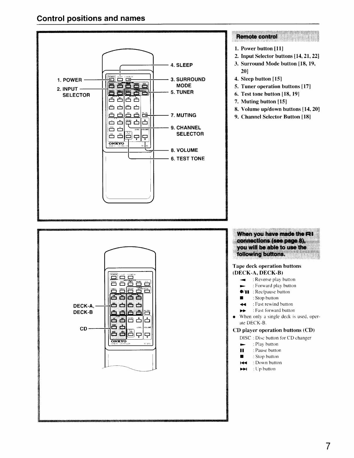
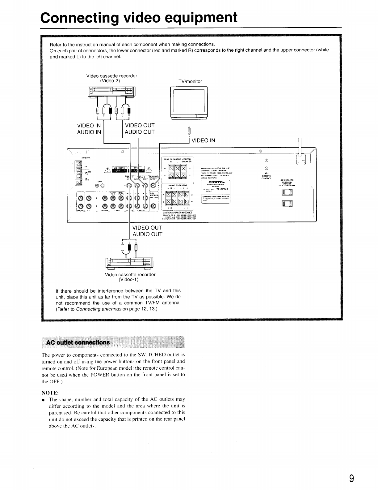
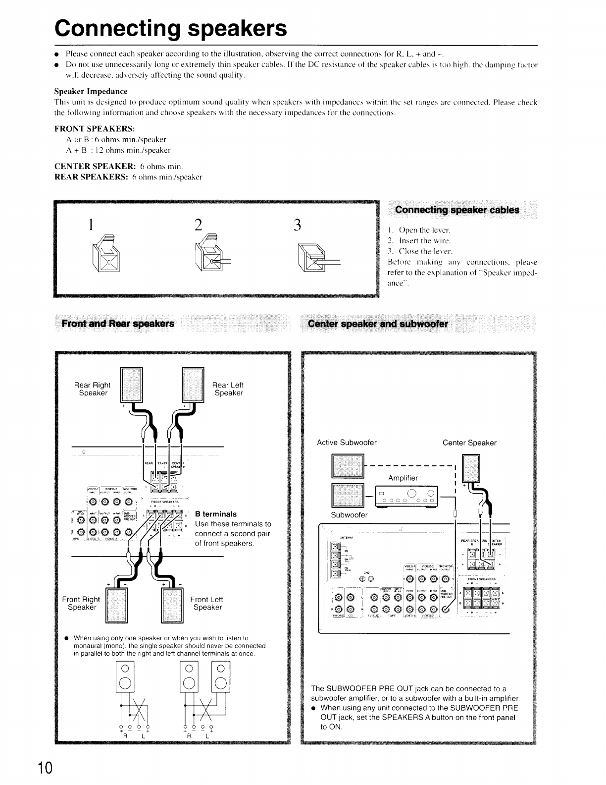
Onkyo TX-SV343 User manual

TX-SV343
Audio
Video
Control
Receiver
Instruction
Manual
he
ME
kes
TW
Sw
hd
<
oa
pont
AS
ab
ae

Thank
you
for
purchasing
the
Onkyo
TX-SV343
Audio
Video
Control
Receiver.
Please
read
this
manual
thoroughly
before
making
connections
and
operating
the
unit.
Following
the
instructions
in
this
manual
will
enable
you
to
obtain
optimum
performance
and
listening
enjoyment
from
your
new
A/V
Receiver.
Please
retain
this
manual
for
future
reference.
Features
Power
output:
USA
&
Canadian
modeis:
Stereo
mode
60
watts
per
channel,
min.
RMS
into
8
ohms,
both
channels
driven
from
20
Hz
to
20
kHz
with
no
more
than
0.08%
THD.
Surround
mode
Front
L/R
Channels
2
«
50
W
(1
kHz,
0.08%,
8
ohms)
Center
Channel
50
W
(1
kHz,
0.15%.
8
ohms)
Rear
Channels
(Rear
channel
only
driven)
ISW+!5W
(1
kHz,
0.3%,
8
ohms}
European
models:
Stereo
mode
2
Xx
60
watts
at
6
ohms
(DIN)
Surround
mode
Front
L/R
and
Center
Channels
3
x
50
watts
at
6
ohms
(DIN)
Rear
Channels
(Rear
channel
only
driven)
15
watts
+
|S
watts
at
6
ohms
(DIN)
Asian
models:
Note
to
CATV
system
installer:
e
This
reminder
is
provided
to
call
the
CATV
system
installer’s
attention
to
Section
820-40
of
the
NEC
which
provides
guide-
lines
for
proper
grounding
and,
in
particular,
specifies
that
the
cable
ground
shall
be
connected
to
the
grounding
system
of
the
building,
as
close
to
the
point
of
cable
entry
as
practical.
e@
For
models
having
a
power
cord
with
a
polarized
plug.
CAUTION:
TO
PREVENT
ELECTRIC
SHOCK,
MATCH
WIDE
BLADE
OF
PLUG
TO
WIDE
SLOT,
FULLY
INSERT.
e
Sur
les
modeéles
dont
la
fiche
est
polarisée.
ATTENTION:
POUR
EVITER
LES
CHOCS
ELEC-
TRIQUES.
INTRODUIRE
LA
LAME
LA
PLUS
LARGE
DE
LA
FICHE
DANS
LA
BORNE
CORRESPONDANTE
DE
LA
PRISE
ET
POUSSER
JUSQU’
AU
FOND.
Declaration
of
Conformity
We,
ONKYO
EUROPE
ELECTRONICS
GMBH
INDUSTRIESTRASSE
18/20
82110
GERMERING,
GERMANY
declare
in
own
responsibility.
that
the
ONK
YO
product
described
in
this
instruction
manual
1s
in
compliance
with
the
corresponding
technical
standards
such
as
ENSS5013,EN55020,.EN60555-2.
EN60065
Stereo
mode
an
2
x
80
watts
at
6
ohms,
1
kHz
(EIAD
GERMERING,GERMANY
ALE
Surround
mode
H.
YAMAZOE
Front
L/R
and
Center
Channels
3
x
65
watts
at
6
ohms,
|
kHz
(EIAJ)
ONKYO
EUROPE
ELECTRONICS
GMBH
Rear
Channels
(Rear
channel
only
driven)
20
watts
+
20
watts
at
6
ohms,
|
kHz
(EIAJ)
e
Dolby
Pro
Logic
and
Hall
Surround
mode
for
spacious
sound
Replacement
and
mounting
of
an
AC
plug
on
the
power
supply
cord
e
All
channels
boast
discrete
output
stage
circuits
(extremely
of
this
unit
should
be
performed
only
by
qualified
service
personnel,
rare
in
this
receiver
class)
for
accurate
high-current,
low-
IMPORTANT:
impedance
drive
e
Costly,
high-quality
parts
such
as
large
power
transistors,
oversized
transformer
and
a
heavy-duty,
one-piece,
extruded
The
wires
in
the
mains
lead
are
coloured
in
accordance
with
the
following
code:
Battery-free
memory
backup
fRI
Compatible
remote
control
for
the
ASTA
mark
or
the
BSI
mark
on
the
body
of
the
fuse.
IF
THE
FITTED
MOULDED
PLUG
IS
UNSUITABLE
FOR
THE
SOCKET OUTLET
IN
YOUR
HOME
THEN
THE
FUSE
Manufactured
under
license
from
Dolby
Laboratories
Licens-
SHOULD
BE
REMOVED
AND
THE
PLUG
CUT
OFF
AND
ing
Corporation.
DISPOSED
OF
SAFELY.
THERE
!S
A
DANGER
OF
SEVERE
DOLBY,
the
double-D
symbol
DO
and
“PRO
LOGIC”
are
ELECTRICAL
SHOCK
IF
THE
CUT
OFF
PLUG
IS
INSERTED
trademarks
of
Dolby
Laboratories
Licensing
Corporation.
INTO
ANY
13
AMP
SOCKET.
If
in
any
doubt
please
consult
a
qualified
electrician.
heat
sink
enhance
low-impedance
drive
capability
Blue:
Ne
utral
e
Dedicated
line-level
subwoofer
output
Brown:
Live
a
e
4
Audio
and
2
AV
inputs
accommodate
a
complete
AV
system
As
the
colours
of
the
wires
in
the
mains
lead
of
this
appliance
may
e
A/B
Speaker
selector
and
outputs
not
correspond
with
the
coloured
markings
identifying
the
termt-
e
Tape
monitor
nals
in
your
plug,
proceed
as
follows:
e
Adjustable
digital
delay
The
wire
which
is
coloured
BLUE
must
be
connected
to
the
terminal
e
30
FM/AM
random
presets
in
the
plug
which
ts
marked
with
the
letter
N
or
coloured
BLACK.
e
Preset
scan
tuning
The
wire
which
is
coloured
BROWN
must
be
connected
to
the
termi-
e
3
Station
group
presets
(10
stations
per
group)
nal
in
the
plug
which
is
marked
with
the
letter
L
or
coloured
RED.
e
RDS
with
PS
(European
models
only)
e
Direct
access
tuning
IMPORTANT
e
Motor-driven,
precision
4-gang
volume
control
A
5
amp
fuse
is
fitted
in
this
plug.
Shoud
the
fuse
need
to
be
e
Headphone
jack
replaced
please
ensure
that
the
replacement
fuse
has
a
rating
of
5
e
Audio
mute,
sleep
timer
(via
remote)
amps
and
that
it
is
approved
by
ASTA
or
BSI
to
BS
1362.
Check
e
e

“WARNING”
“TO
REDUCE
THE
RISK
OF
FIRE
OR
ELECTRIC
SHOCK,
DO
NOT
EXPOSE
THIS
APPLIANCE
TO
RAIN
OR
MOIS-
TURE.”
CAUTION:
“TO
REDUCE
THE
RISK
OF
ELECTRIC
SHOCK,
DO
NOT
REMOVE
COVER
(OR
BACK).
NO
USER-SERVICEABLE
PARTS
INSIDE.
REFER
SERVICING
TO
QUALIFIED
SER-
VICE
PERSONNEL.”
Important
safeguards
l.
ond
6A.
10.
Read
Instructions
—
All
the
safety
and
operating
instructions
should
be
read
before
the
appliance
ts
operated.
Retain
Instructions
—
The
safety
and
operating
instructions
should
be
retained
for
future
reference.
Heed
Warnings
-
All
warnings
on
the
appliance
and
in
the
operat-
ing
instructions
should
be
adhered
to,
Follow
Instructions
—
All
operating
and
use
instructions
should
be
followed.
Water
and
Moisture
—
The
appliance
should
not
be
used
near
waler
—
for
example,
near
a
bathtub,
washbow!l,
kitchen
sink,
laundry
tub,
in
a
Wet
basement.
or
near
a
swimming
pool,
and
the
like.
Carts
and
Stands
-
The
appliance
should
be
used
only
with
a
cart
or
stand
that
is
recommended
by
the
manufacturer.
An
appliance
and
cart
combination
should
be
moved
with
care.
Quick
stops,
excessive
force.
and
uneven
PORTABLE
CART
WARNING
surfaces
may
cause
the
appliance
and
cart
combination
to
overturn,
S3125A
we
Wall
or
Ceiling
Mounting
—
The
appliance
should
be
mounted
to
a
wall
or
ceiling
only
as
recommended
by
the
manufacturer.
Ventilation
—
The
appliance
should
be
situated
so
that
its
location
or
position
does
not
interfere
with
its
proper
ventilation.
For
example,
the
appliance
should
not
be
situated
on
a
bed,
sofa,
rug,
or
similar
sur-
face
that
may
block
the
ventilation
openings:
or
if
placed
in
a
built-in
installation,
such
as
a
book
case
or
cabinet
that
may
impede
the
flow
of
air
through
the
ventilation
openings,
there
should
be
tree
space
of
at
least
20
cm
and
open
up
behind
the
apphance.
Heat
-
The
appliance
should
be
situated
away
from
heat
sources
such
as
radiators.
heat
registers,
stoves.
or
other
appliances
(including
ampltters)
that
produce
heat.
Power
Sources
—
The
appliance
should
be
connected
to
a
power
supply
only
of
the
type
described
in
the
operating
instructions
or
as
marked
on
the
appliance.
.
Polarization
—
If
the
appliance
is
provided
with
a
polarized
plug
having
one
blade
wider
than
the
other,
please
read
the
following
infor-
mation:
The
polarization
of
the
plug
is
a
safety
feature.
The
polarized
plug
will
only
fit
the
outlet
one
way.
If
the
plug
does
not
fit
fully
into
the
outlet.
try
reversing
it.
If
there
is
still
trouble
inserting
it,
the
user
should
seek
the
services
of
a
qualified
electrician.
Under
no
circum-
stances
should
the
user
attempt
to
defeat
the
polarization
of
the
plug.
.
Power-Cord
Protection
—
Power-supply
cords
should
be
routed
so
that
they
are
not
likely
to
be
walked
on
or
pinched
by
items
placed
upon
or
against
them,
especially
near
plugs,
convenience
receptacles.
and
the
point
where
they
exit
from
the
appliance.
Ad
13.
RISK
OF
ELECTRIC
SHOCK
DO
NOT
OPEN
@
The
lightning
flash
with
arrowhead
symbol,
within
an
equilateral
triangle,
is
intended
to
alert
the
user
to
the
presence
of
uninsuiated
“dangerous
voltage”
within
the
product's
enclosure
that
may
be
of
suffi-
cient
magnitude
to
constitute
a
risk
of
electric
shock
to
persons.
@
The
exclamation
point
within
an
equilateral
triangle
is
intended
to
alert
the
user
to
the
presence
of
important
operating
and
maintenance
(servicing)
instructions
in
the
literature
accompanying
the
product.
Cleaning
—
The
appliance
should
be
cleaned
only
as
recommended
by
the
manufacturer.
.
Power
Lines
—-
An
outdoor
antenna
should
be
located
away
from
power
lines.
.
Nonuse
Periods
—
The
power
cord
of
the
appliance
should
be
unplugged
trom
the
outlet
when
left
unused
for
a
long
period
of
time.
.
Object
and
Liquid
Entry
—
Care
should
be
taken
so
that
objects
do
not
fal]
and
liquids
are
not
spilled
into
the
enclosure
through
open-
ings.
.
Damage
Requiring
Service
—
The
appliance
should
be
serviced
by
qualified
service
personnel
when:
A.
The
power-supply
cord
or
the
plug
has
been
damaged;
or
B.
Objects
have
fallen,
or
liquid
has
been
spilled
into
the
appliance;
Or
C.
The
apphance
has
been
exposed
to
rain;
or
D.
The
appliance
does
not
appear
to
operate
normally
or
exhibits
a
marked
change
in
performance;
or
E.
The
appliance
has
been
dropped,
or
the
enclosure
damaged.
.
Servicing
-
The
user
should
not
attempt
to
service
the
appliance
beyond
that
described
in
the
operating
instructions.
All
other
servicing
should
be
referred
to
qualified
service
personnel.
.
Outdoor
Antenna
Grounding
-—
If
an
outside
antenna
is
con-
nected
to
the
receiver,
be
sure
the
antenna
system
is
grounded
so
as
to
provide
some
protection
against
voltage
surges
and
built
up
static
charges.
Article
810
of
the
National
Electrical
Code,
ANSI/NFPA
70,
provides
information
with
regard
to
proper
grounding
of
the
mast
and
supporting
structure,
grounding
of
the
lead-in
wire
to
an
antenna
dis-
charge
unit,
size
of
grounding
conductors,
location
of
the
antenna-dis-
charge
unit,
connection
to
grounding
electrodes,
and
requirements
for
the
grounding
electrode.
See
Figure
73.1.
FIGURE
73.1:
EXAMPLE
OF
ANTENNA
GROUNDING
AS
PER
NATIONAL
ELECTRICAL
CODE
_--
ANTENNA
LEAD
IN
WIRE
~
ANTENNA
“|
DISCHARGE
UNIT
(NEC
SECTION
810-20)
ELECTRIC
SERVICE
EQUIPMENT
--__
“=~
GROUNDING
CONDUCTORS
(NEC
SECTION
810-21)
tm
==
POWER
SERVICE
GROUNDING
ELECTRODE
SYSTEM
(NEC
ART
256,
PART
H}
NEC
—
NATIONAL
ELECTRICAL
CODE
S2898A

Precautions
Ll.
Warranty
Claim
You
can
find
the
serial
number
on
the
rear
panel.
In
case
of
war-
ranty
claim,
please
report
this
number.
2.
Recording
Copyright
Recording
of
copyrighted
material
for
other
than
personal
use
is
illegal
without
permission
of
the
copyright
holder.
3.
AC
Fuse
The
fuse
is
located
inside
the
chassis
and
is
not
user-serviceable.
If
power
does
not
come
on,
contact
your
Onkyo
authorized
service
station.
4.
Care
From
time
to
time
you
should
wipe
the
front
and
rear
panels
and
the
cabinet
with
a
soft
cloth.
For
heavier
dirt,
dampen
a
soft
cloth
in
a
weak
solution
of
mijid
detergent
and
water,
wring
it
out
dry,
and
wipe
off
the
dirt.
Following
this,
dry
immediately
with
a
clean
cloth.
Do
not
use
rough
material.
thinners,
alcohol
or
other
chemi-
cal
solvents
or
cloths
since
these
could
damage
the
finish
or
remove
the
panel
lettering.
5.
Power
WARNING
BEFORE
PLUGGING
IN
THE
UNIT
FOR
THE
FIRST
TIME.
READ
THE
FOLLOWING
SECTION
CAREFULLY.
@
Some
models
are
designed
for
use
only
with
the
power
supply
voltage
of
the
region
where
they
are
sold.
European
and
Australian
models:
AC
230V.
S5OHz
U.S.A.
and
Canadian
models:
AC
120V.
60Hz
Worldwide
model:
AC
220-230V/120V
switchable,
50/60Hz.
Other:
AC
220V,
60Hz
e
Voltage
Selector
(Rear
Panel)
Worldwide
models
are
equipped
with
a
voltage
selector
to
con-
form
to
local
power
supplies.
Be
sure
to
set
this
switch
to
match
the
voltage
of
the
power
supply
in
your
area
before
plugging
in
the
unit.
Models
without
a
voltage
selector
can
only
be
used
in
areas
where
the
power
supply
is
the
same
as
that
of
the
unit.
e@
The
power
does
not
shut
off
completely
by
just
turning
the
power
off.
So
power
cord
should
be
removed
from
AC
outlet
when
not
in
use
for
a
prolonged
time.
Memory
Preservation
This
unit
does
not
require
memory
preservation
batteries.
A
built-in
memory
power
back-up
system
preserves
the
contents
of
the
memory
during
power
failures
and
even
when
the
unit
1s
unplugged.
The
unit
must
be
plugged
in
order
to
charge
the
back-up
system.
The
memory
preservation
period
after
the
unit
has
been
unplugged
varies
depending
on
climate
and
placement
of
the
unit.
On
the
average.
memory
contents
are
protected
over
a
period
of
a
few
weeks
after
the
last
time
the
unit
has
been
unplugged.
This
period
is
shorter
when
the
unit
is
exposed
to
a
highly
humid
climate.
Supplied
accessories
Remote
controller
(RC-328S)
(1)
Batteries
(size
AA,
R6,
or
UM-3)
(2)
FM
antenna
(1)
AM
loop
antenna
(1)
(worldwide
and
some
other
models)
(worldwide
model
only)
75/300
ohm
antenna
adaptor
(1)
CV
plug
(Shape
may
vary
according
to
the
area
where
purchased.)
(1)

Before
operating
this
unit
|.
Determine
the
proper
voltage
for
your
area:
220
~
230
V
or
120
V.
2.
If
the
setting
on
the
voltage
selector
1s
not
correct,
insert
a
screwdriver
tnto
the
groove
in
the
switch
and
slide
the
switch
completely
to
the
right
(120
V)
or
the
left
(220
~
230
V),
whichever
is
appropriate.
VOLTAGE
SELECTOR
220-230V™\
AM
FREQ.
STEP
SkHz
‘
ou
me
=
The
worldwide
model
is
equipped
with
a
switch
that
controls
the
AM
(9
kHz/
10
kHz)
band
tuning
steps.
Please
set
this
switch
to
match
the
tuning
step
frequency
in
your
area.
US.
&
Canada:
10
kHz
Other
areas:
9
kHz
Insert
the
batteries
into
the
remote
control
according
to
the
illustration.
The
following
information
will
help
you
:
'
get
optimal
use
from
the
remote
control.
f
@
Place
this
unit
away
from
direct
bright
1)
(2)
(3)
:
light
which
can
prevent
proper
opera-
i
tion
of
the
remote
control.
e
Make
sure
audio
rack
doors
do
not
have
tinted
glass.
Placing
this
unit
behind
such
a
door
may
prevent
proper
remote
control
operation.
Remove
the
battery
compartment
cover
by
opening
it
as
shown
in
the
illustration.
Load
two
AA
(R6
or
UM-3)-size
batteries
into
the
remote
control
with
the
plus
(+)
and
minus
(—)
terminals
positioned
as
indi-
cated
by
the
diagram
inside
the
battery
compartment,
then
close
the
cover.
f
@
Immediately
remove
empty
batteries
to
STAND-BY
indicator
——
=
E
avoid
corrosion
damage.
fF
e
To
avoid
potential
corrosion
damage,
never
mix
old
batteries
with
new
ones.
4
@
The
manganese
batteries
supplied
with
a
|
{
300
va
;
this
unit
have
a
service
life
of
approxi-
us
“
-
|
“approx.
5m
LS
mately
six
months,
depending
on
the
<“
o
|
“
(16
feet)
'
frequency
of
use.
é
Be
The
TX-SV343
comes
equipped
with
two
AA
(R6
or
UM-3)
manganese
bat-
;
e
teries,
but
we
recommend
that
long-life
a
a
e
AA
(LR6
or
AM-3)
size
alkaline
batter-
Z
ies
be
used
when
replacing
the
batteries.
TX-SV343
Remote
control
sensor

Control
positions
and
names
1
7
8 9
1011
12
20
19
18
17 16
15 14
13
USA
&
Canadian
model
1
Display
a
boc
de
f
h
i
k
|
corps
“SPEAKERS
AB]
AUDIOMUTE
FM
MUTE
»
TUNED
SLEEP
“GROUP
TAPE MON.
|
VIDECDJE
ON
OFF
&
STEREO
“MEMORY
|
46
C
Other
than
USA
and
Canadian
model
n
m
For
more
imformation
about
buttons
or
12,
Master
Volume
control
knob
c.
Speaker
selector
indicators
knobs,
turn
to
page
number
listed
in
the
[
].
[14,
20]
d.
Video
input
selector
indicators
13.
Balance
control
knob
[14]
14.
Treble
control
knob
[14]
15.
Bass
control
knob
[14]
e.
Audio
Mute
indicator
f.
FM
Mute
On/Off
indicators
1.
Power
switch
(System
switch)
16.
Direct
Tuning
button
[16]
g.
EM
Stereo
indicator
[1]
ae
17.
Tuning
Up/Down
buttons
[16]
h.
Tuned
indicators
2.
Stand-by/Received
indicator
[11]
1
Input
selector
buttons
[14,
21,22]
i:
Memory
indicator
3.
Remote
control
sensor
[5]
19.
Speaker
selector
buttons
[14]
j.
Sleep
indicator
+.
18
10.20
views
Dutton
20.
Headphone
jack
[15]
k.
RDS
indicator
(European
models
5.
Center
Mode
button
[19]
only)
—
6.
Delay
Time
button
[20]
Il.
Group
indicators
7.
Group
button
[17]
If
there
is
a
protective
film
on
the
surface
m.
Multi
function
display
.
_
Lea
gages
(Preset
station/Sleep
time/
8.
Memory
button
[17]
of
the
display
which
is
making
it
difficult
.
ad
the
displ:
_
Center
&
rear
volume
level/Delay
9.
FM
Mute/Mode
button
[16,
17]
fo
read
the
display,
remove
It.
time)
10.
Number
buttons
(16,
17]
a.
Surround
Mode
indicators
n.
Multi
function
display
11.
Scan
button
[17]
b.
Tape
Monitor
indicator
(Frequency/Input
selector)

Control
positions
and
names
1.
Power
button
[11]
2.
Input
Selector
buttons
[14,
21,
22}
3.
Surround
Mode
button
[18,
19,
20]
4.
SLEEP
POWER
|
ShEPP
504
MOTE
|
ey
1.
POWER
=)
=
=
3.
SURROUND
.
Sleep
button
[15]
2
INPUT
MODE
.
Tuner
operation
buttons
[17]
SELECTOR
9.
TUNER
.
Test
tone
button
[18,
19]
.
Muting
button
[15]
.
Volume
up/down
buttons
[14,
20]
.
Channel
Selector
Button
[18]
7.
MUTING
we
on
DN
i
bh
9.
CHANNEL
SELECTOR
8.
VOLUME
6.
TEST
TONE
Tape
deck
operation
buttons
(DECK-A,
DECK-B)
~a
Reverse
play
button
wm
>
Forward
play
button
@/5E
:
Rec/pause
button
a
:
Stop
button
440.
Fast
rewind
button
pe
>
Fast
forward
button
e
When
only
a
single
deck
is
used,
oper-
ate
DECK-B.
CD
player
operation
buttons
(CD)
DISC
:
Disc
button
for
CD
changer
m
©
Play
button
il
:
Pause
button
a
:
Stop
button
Kid
=
>
Down
button
mel
=
Up
button

Connecting
audio
equipment
.
Refer
to
the
instruction
manual
of
each
component
when
making
connections.
)\————(_”
On
each
pair
of
connectors,
the
lower
connector
(red
and
marked
R)
corresponds
to
the
right
channel
and
the
upper
connector
(white
and
marked
L)
to
the
left
channel.
Turntable
To
wall
outlet
CAUTION:
Do
not
plug
in
the
power
cord
until
all
connec-
tions
have
been
made.
REAR
SPEAKERS
CENTER
R
L
SPEAKER
MANUFACTURED
UNDER
LCEMSE
FROM
DCR?
SABORA
TORIES
LICENSING
CORPORATION
“DOLaT’
TRE
DOUBLED
SYMBOL
AND
“SAC
LOG”
Al
WIDEOIY
VIDEO-2
MONITOR)
|
ARE
"RADEMARES
OF
DOLBY
LABORATORIES
AEMOTE
|
INPLIT
2
OITPUT
INPUT
°
QUTPLUT
|
|
Sur
LICENSING
CORPORATION
CONTROL
4
AC
OUTLETS
ONEYO=s
!
aC120¥
a0Hz
SHED
~
y
:
SWITCH
FRONT
SPEAKERS
AVG
VIDED
CONTRDL
TOTAL
120W
(4
MAX
CORPORATION
|
FON
SSeNCSCRE
AGA
Sh
GsARL
”
i
RECEWER
A
+A
-
-
Lb
+
MODELNO.
TX-S¥343
|
re
(en
HATING
|i
|
wa
|
NF
we
A
|
ae
aN
=
=|
OD
-
OOVOOOO
Er
_
+A
- -
i+
pHnwal
J:
i
pretense
ee
seen
:
CAUTION:
SPEAKER
IMPEDANCE
FRONT
AOA
BR:
6
OHMS
MIN,
/
SPEAKER
FRONT
A+G:
12
OHMS
MIN.)
SPEAKER
CENTER
AERA:
&
OHMS
MIN.)
SPEAKER
CD
player
Tape
deck
Cassette
tape
decks
and
a
compact
disc
player
that
are
equipped
with
an
Onkyo
FRE
connector
can
be
operated
using
the
remote
control
included
with
this
unit.
To
enable
remote
control
operation
of
other
components,
connect
the
remote
control
cable
as
shown
at
the
left.
TX-SV343
NOTE:
@
To
enable
proper
remote
control
operation,
both
the
RI
cables
and
the
audio
cables
must
be
connected
to
the
units.
e
This
units
remote
contro!
cannot
be
used
to
control
Onkyo
turntables.
@
AnfRI
remote
control
cable
equipped
with
1/8”
(3.5
mm)
mini
jacks
ts
included
with
any
other
component
installed
with
an
fR#
connector.
The
direct
function
feature
When
a
compact
disc
player,
and
tape
deck
with
the
RI
con-
nector
are
connected
together,
you
can
use
the
direct
func-
tion
feature.
Simply
by
directly
operating
the
desired
component
(com-
pact
disc
player
or
tape
deck),
this
unit's
Input
Selector
auto-
matically
switches
to
that
component.
It
is
not
necessary
to
switch
this
unit’s
Input
Selector
when
changing
listening
sources.

Connecting
video
equipment
Refer
to
the
instruction
manual
of
each
component
when
making
connections.
On
each
pair
of
connectors,
the
lower
connector
(red
and
marked
R)
corresponds
to
the
right
channel
and
the
upper
connector
(white
and
marked
L)
to
the
left
channel.
Video
cassette
recorder
(Video-2)
TV/monitor
VIDEO
IN
AUDIO
IN
VIDEO
OUT
AUDIO
OUT
-
i
_
ANTENNA
a,
REAR
SPEAKERS
CENTER
L
SPEAKEA
©
MANUFACTUREC
UNDER
UCENSE
FROM
DOLSY
LABORATORIES
ICENSING
CORPORATION
“Di
BY".
THE
GOUBLE-D
SYMBOL
ANG
“PAO
.0G'C”
ARE
*RACEMARRS
OF
DOLBY
LASORATORIES
LCEMSNG
CORPORATION
ONKYO.s
2
(MONITOR
OUTPUT
Uf
i
|
aU
VIDEO
CONTROL
RECEIVER
®
Al
AEMOTE
CONTROL
AC
OUTLETS
AC
120
EOHz
SWITCHED
TOTAL
120
1A
MAK
!
MODEL
NG
7X-S¥343
INPUT
71
RATIBE:
PLAT
.
|
.
OWEYO
COMPOR
ATION
2
MSSHIN-CHG
NEV
AGA
A
Se
OSAKA,
|
_#
CAUTION:
SPEAKER
IMPEDANCE
FRONT
AOA
B:
OHMS
MIN.
/
SPEAKER
FRONT
A+B:
17
CHMS
MIN.
!
SPEAKER
CENTER
/
AE
A&A
VIDEO
OUT
AUDIO
OUT
}
ROD
Rod
Ger
|
iS
Sok
TAPE
WIPO
WIDEO-2
A
5
GHMS
MIN.
/
SPEAKER
Video
cassette
recorder
(Video-1)
If
there
should
be
interference
between
the
TV
and
this
unit,
place
this unit
as
far
from
the
TV
as
possible.
We
do
not
recommend
the
use
of
a
common
TV/FM
antenna.
(Refer
to
Connecting
antennas
on
page
12,
13.)
The
power
to
components
connected
to
the
SWITCHED
outlet
1s
turned
on
and
off
using
the
power
buttons
on
the
front
panel
and
remote
control.
(Note
for
European
model:
the
remote
control
can-
not
be
used
when
the
POWER
button
on
the
front
panel
is
set
to
the
OFF.)
NOTE:
The
shape,
number
and
total
capacity
of
the
AC
outlets
may
differ
according
to
the
model
and
the
area
where
the
unit
is
purchased.
Be
careful
that
other
components
connected
to
this
unit
do
not
exceed
the
capacity
that
is
printed
on
the
rear
panel
above
the
AC
outlets.

Connecting
speakers
e
Please
connect
each
speaker
according
to
the
lustration,
observing
the
correct
connections
for
R,
L,
+
and
-.
@
Do
not
use
unnecessarily
long
or
extremely
thin
speaker
cables.
If
the
DC
resistance
of
the
speaker
cables
is
too
high.
the
damping
factor
will
decrease.
adversely
affecting
the
sound
quality.
Speaker
Impedance
This
unit
is
designed
to
produce
optimum
sound
quality
when
speakers
with
impedances
within
the
set
ranges
are
connected.
Please
check
the
following
information
and
choose
speakers
with
the
necessary
impedances
for
the
connections.
FRONT
SPEAKERS:
A
or
B:6
ohms
min./speaker
A+B
:12
ohms
min./speaker
CENTER
SPEAKER:
6
ohms
min.
REAR
SPEAKERS:
6
ohms
min./speaker
|.
Open
the
lever.
2.
Insert
the
wire.
3,
Close
the
lever.
Before
making
any
connections,
please
refer
to
the
explanation
of
“Speaker
imped-
ance.
Rear
Left
Speaker
Rear
Right
Speaker
Active
Subwoofer
Center
Speaker
WIDEG-TY
—
¥IDEO.2
TMON:TOR!
WRT
|
OUTPUT
IWPUT
©
OUTPUT
\
|
a,
f
ae
i
12
'
©
1
©
|
MPT
Jouteur
INPUT
'
SUBE
H
.
=
|
=)
WOOFER
A
is
4
Ff;
q
PR
T
O|AIO
O
==
wea
|e
\
|
A
A,
©)
©
GC
—
_Mpeo
VIDEO?
an
7
FRONT
SPEAKERS
‘Om
©
km
B
terminals
Use
these
terminals
to
connect
a
second
pair
of
front
speakers.
[VIDEO-4{
VIDEO-2
TMONITOR’
INPUT
[OUTPUT
INPUT
|
OUTPUT
i
:
INPUT
sup.
a
|
ttle
AAA
AA
Front
Left
©|©
©O.©
©|O0/\©
Speaker
~
-
on
Front
Right
Speaker
@
When
using
only
one
speaker
or
when
you
wish
to
listen
to
monaural
(mono),
the
single
speaker
should
never
be
connected
in
parallel
to
both
the
right
and
left
channel
terminals
at
once.
O)
The
SUBWOOFER
PRE
OUT
jack
can
be
connected
to
a
subwoofer
amplifier,
or
to
a
subwoofer
with
a
built-in
amplifier.
e
When
using
any
unit
connected
to
the
SUBWOOFER
PRE
OUT
jack,
set
the
SPEAKERS
A
button
on
the
front
panel
to
ON.
10

Positioning
speakers
Speaker
placement
plays
an
tmportant
role
in
the
reproduction
of
Surround
sound,
The
manner
in
which
the
speakers
are
placed
varies
depending
on
the
size
of
the
room
and
the
wall
coverings
used
in
the
room.
The
illustration
below
shows
an
example
of
a
layout
for
standard
speaker
placement.
Refer
to
this
example
when
positioning
the
speakers
in
order
to
experience
the
best
of
Surround
sound.
For
ideal
Surround
effects,
all
speakers
should
be
installed.
If
a
center
speaker
or
subwoofer
is
not
connected,
the
sound
from
the
unused
channel
is
properly
distributed
to
the
con-
|
nected
speakers
in
order
to
produce
the
best
Surround
sound
Sub
;
possible.
uo-
4
wooter
senner
Front:
speaker
|
f
The
left,
right
and
center
speakers
should
face
the
seated
lis-
tener
and
be
placed
at
ear
level.
The
center
speaker
produces
a
richer
sound
image
by
enhancing
the
perception
of
the
sound's
source
and
movement.
Rear:
Place
the
left
and
right
Rear
speakers
|
m
(3
feet)
above
the
listener’s
ear
level
and
toward
the
sides
of
the
room,
making
speaker
spuaker
sure
that
the
listener
is
within
the
speakers’
dispersion
angle.
Left
on,
[7
Right
These
speakers
produce
the
feel
of
a
moving
sound
while
:
|
generating
the
sensation
of
being
in
the
middle
of
the
action.
|
Sg
|
|
Subwoofer:
Install
a
subwoofer
with
a
built-in
power
amplifier
for
pow-
erful
bass
sounds.
The
placement
of
the
subwoofer
does
not
affect
the
final
quality
of
the
sound
image
too
much,
so
you
can
install
it
with
the
room
layout
in
mind.
Refer
to
the
speaker
instruction
manual
for
more
details.
Connecting
the
power
Betore
plugging
in
the
unit.
confirm
that
all
connections
have
been
made
properly.
Before
turning
on
the
power,
be
sure
that
the
MASTER
VOLUME
control
knob
is
fully
turned
counterclockwise.
Turning
on
this
unit’s
power
may
cause
a
momentary
power
surge.
which
might
interfere
with
other
electrical
equipment.
such
as
comput-
ers.
[f
so.
use
a
wall
outlet
on
a
different
circuit.
U.S.
and
Canadian
medels:
Plugging
the
TX-SV343"s
power
cord
into
an
AC
outlet
puts
POWER
switch
the
unit
in
stand-by
status
(the
STAND-BY
indicator
is
lit).
Pressing
the
POWER
switch
turns
on
the
unit
and
lights
up
the
Display.
If
this
switch
is
pressed
again,
the
unit
returns
to
the
stand-by
status,
The
POWER
button
on
the
remote
control
is
used
in
the
same
way
as
the
POWER
switch
on
the
TX-SV343.
Models
other
than
U.S.
and
Canadian
models:
After
plugging
the
TX-SV343°s
power
cord
into
an
AC
out-
SYSTEM
switch
let.
press
the
SYSTEM
switch
to
put
the
unit
in
power-on
sta-
tus
(the
unit
can
be
operated
and
its
display
is
lit).
The
remote
control
cannot
be
used
to
operate
the
TX-SV343
if
the
SYS-
TEM
switch
1s
not
set
to
ON.
When
the
SYSTEM
switch
is
set
to
ON,
pressing
the
POWER
button
on
the
remote
control
switches
the
TX-SV343
between
stand-by
status
(the
STAND-BY
indicator
is
lit)
and
power-
on
status
(the
Display
is
lit).
Pressing
the
SYSTEM
switch
on
the
TX-SV343
to
set
it
to
OFF
turns
off
the
unit.
(When
the
SYSTEM
switch
is
set
to
OFF,
only
a
smail
amount
of
power
ts
used.)
11

Connecting
antennas
Insert
into
the
slot.
Outdoor
Indoor
FM/TV
T-shaped
antenna
antenna
Se
300
ohm
ribbon
wire
Directional
linkage
type
splitter
To
TX-SV343
To
TV
(or
VCR)
12
Press
down
on
the
lever.
Insert
the
wire.
Return
the
lever.
Assemble
the
loop
antenna
as
shown
in
the
illustration.
(Refer
to
the
next
page
for
details
on
connecting
the
AM
loop
antenna.)
Connecting
the
T-shaped
antenna
or
300
ohm
ribbon
wire
to
the
75/300
ohm
adaptor
Loosen
the
screws
and
wrap
the
wires
around
them.
Then,
tighten
the
screws
with
a
screwdriver.
Connecting
the
coaxial
cable
to
the
75/300
ohm
adaptor
1.
With
your
fingernail
or
a
smali
screwdriver,
pull
the
stop-
pers
outwards
and
remove
the
cover.
Remove
the
transformer
wire
A
from
slit
B
and
insert
it
into
shtC.
3.
Prepare
the
coaxial
cable
as
shown
in
the
illustration.
Connect
the
coaxial
cable
to
the
75/300
ohm
antenna
adaptor.
Io
(>
Insert
the
end
of
the
cable.
(2)
Use
pliers
to
pinch
it
and
keep
it
in
place.
4.
Re-install
the
cover.
Do
not
use
the
same
antenna
for
both
FM
and
TV
(or
VCR)
reception
since
the
FM
and
TV
(or
VCR)
signals
can
inter-
fere
with
each
other.
If
you
must
use
a
common
FM/T'Y
(or
VCR)
antenna,
use
a
directional
linkage
type
splitter.

Connecting
antennas
The
T-shaped
FM
antenna
ts
for
indoor
use
only.
Extend
the
antenna
and
move
it
until
the
clearest
signal
is
received.
Use
tacks
or
similar
objects
to
fix
it
in
the
T-shaped
arrangement
giving
the
least
amount
of
distortion.
The
AM
loop
antenna
is
also
for
indoor
use
only.
Position
it
where
the
clearest
sound
is
received.
Put
it
as
far
as
possibile
away
from
this
unit,
the
TV,
speaker
cables
and
power
cords.
If
clear
signals
cannot
be
received
using
only
the
enclosed
T-shaped
FM
antenna
or
AM
loop
antenna,
connect
an
outdoor
FM
or
outdoor
AM
antenna
as
needed.
c
U.S.
&
Canada
Others
The
outdoor
AM
antenna
will
be
more
effective
if
it
1s
stretched
horizontally
above
a
window
or
outside.
(Do
not
disconnect
the
AM
loop
antenna.
)
U.S.
&
Canada
Others
Be
sure
that
the
outdoor
FM
antenna
is
positioned
as
follows:
e
Keep
the
antenna
away
trom
noise
sources,
such
as
neon
signs
and
busy
roads.
e
Do
not
position
it
near
power
lines,
etc.
This
is
very
dangerous.
|
U.S.
&
Canada
|
Others
lr
ANTENNA
13

Listening
to
your
favorite
source
1.
Press
the
SPEAKERS
A
button.
SPEAKERS
A
indicator
lights
up.
2.
Press
the
desired
input
selector
button
(e.g.
PHONO).
The
appropriate
letters
(e.g.
PHONO)
appear
on
the
display.
Confirm
that
the
TAPE
MON.
indicator
is
off
when
a
source
other
than
the
TAPE
(MONITOR)
has
been
selected.
Also
check
the
audio
muting
1s
off.
3.
Start
the
selected
input
source
playing.
Follow
the
operating
instructions
of
that
unit.
4.
Adjust
the
volume
to
appropriate
level
using
the
MASTER
VOLUME
control
knob
or
VOLUME
A
(up)/¥
(down)
buttons
on
the
remote
control.
5.
Adjust
the
tone
controls
for
your
desired
tone.
SPEAKERS
A:
This
button
turns
on
or
off
the
speakers
connected
to
the
FRONT
A,
CENTER
and
REAR
SPEAK-
ERS
terminals.
When
the
speakers
are
turned
on.
the
SPEAKERS
A
indicator
Itghts
up.
SPEAKERS
B:
This
button
turns
on
or
off
the
speakers
connected
to
the
FRONT
B
SPEAKERS
terminals.
When
the
speakers
are
turned
on,
the
SPEAKERS
B
indicator
lights
up.
SPEAKERS
A
a)
SPEAKERS
B
a
|
Note:
Surround
sound
activated
can
not
operate
A
+
B
speaker
simultaneously.
Treble
and
Bass
are
effectively
only
for
the
Front
left
and
right
speakers.
The
best
results
are
obtained
from
DOLBY
PRO
LOGIC
Surround
when
the
center
and
Jeft
and
right
front
speakers
contain
the
same
amounts
of
mid
and
high
frequencies.
As
the
Treble
and
Bass
contro!
do
not
affect
the
Center
speaker,
adjust
the
tone
controls
for
the
left
and
right
front
speakers
to
match
the
sound
given
by
the
center
speaker,
Because
of
this.
we
recommend
the
use
of
a
good
quality
center
speaker.
BASS:
Adjust
to
strengthen
or
weaken
bass
response.
TREBLE:
Adjust
to
strengthen
or
weaken
treble
response.
BALANCE:
Use
to
adjust
the
relative
volume
levels
of
the
right
and
left
front
speaker
systems
and
headphones.
TREBLE
BALANCE
~
a.
14

Listening
to
your
favorite
source
Stereo
headphones
with
a
standard
stereo
jack
plug
can
be
connected
to
the
PHONES
jack.
The
sound
heard
through
the
head-
phones
is
the
same
sound
that
can
be
heard
from
the
Front
speakers.
although
it
may
be
slightly
different
from
what
is
heard
from
the
speakers
when
the
Surround
made
is
used.
(The
sound
from
the
headphones
may
sound
a
little
distant.)
x 4
nr
|
SPEAKERS
A
AUBIO
MUTE
s
ore
Press
the
MUTING
button
on
the
remote
ve
EE
row
control.
weve
gxwue
MS
Hesers
This
button
temporarily
switches
off
the
sound
from
the
speakers
or
headphones.
The
AUDIO
MUTE
indicator
will
flash.
To
cancel,
@
press
the
MUTING
button
again,
or
e
turn
the
power
off,
then
on.
The
sleep
timer
can
power
off the
system
after
a
specified
time
period.
To
operate
this
function,
use
the
remote
control
supplied
with
your
TX-SV343.
1.
Start
the
source
playing
that
you
would
like
to
listen
to.
(CD,
tape
or
radio
broadcast)
2.
Set
the
amount
of
time
after
which
you
want
the
system
to
turn
off.
The
sleep
timer
works
for
up
to
90
minutes.
You
can
shorten
the
timer
by
[0
minutes
increments
by
pressing
the
SLEEP
button
until
the
desired
time
has
been
reached.
When
the
set
ume
comes,
the
power
will
be
switched
off
automatically.
VIBEO
90
80
70
7
Lo
Cancel
~—
10
=——
20
~—
LEVEL
VOLE
Cancelling
the
sleep
setting
Press
the
SLEEP
button
until
tt
changes
to
the
source
display
you
are
listening
to.
OF
The
timer
can
also
be
cancelled
while
it
ts
in
operation,
by
turning
off
the
power.
15

Tuning
in
a
radio
station
<4
DOWN
TUNING
UP
>
DIRECT
TUNING
Number
buttons
.
Press
either
the
FM
or
AM
button
on
the
main
unit.
2.
Change
the
frequency
using
the
<4
DOWN
or
UP
TUNING
button.
Press
the
«@
DOWN
TUNING
button
to
decrease
the
tre-
quency
and
press
the
UP
TUNING
button
to
increase
the
frequency.
The
TUNED
indicator
in
the
display
lights
up
when
the
station
is
properly
tuned
in.
In
FM,
each
press
of
a
TUNING
button
changes
the
fre-
quency
in
100
or
50
kHz
steps:
in
AM,
the
frequency
changes
in
steps
of
9
or
10
kHz,
depending
on
the
area
where
the
unit
is
used.
a=
DOWN
TUNING
If
a
button
1s
continuously
held
down
for
more
than
0.5
sec-
onds
while
tuning
an
FM
station,
the
frequencies
are
scanned
and
tuning
automatically
stops
when
a
broadcast
1s
received.
!.
Press
either
the
FM
or
AM
button
on
the
main
unit.
2.
Press
the
DIRECT
TUNING
button.
*..
--”
flashes
in
the
display
for
16
seconds.
3.
While
‘“--
--’’
flashes,
enter
the
frequency
using
the
number
buttons.
For
example,
to
enter
“$8.10
MHz’,
press
the
8,
8,
1,
a.)
;
then
0/10
number
buttons.
L_—_
The
TUNED
indicator
in
the
display
lights
up
when
the
station
1s
properly
tuned
in.
If
you
enter
a
frequency
that
is
out
of
range,
the
frequency
display
will
flash
and
the
unit
will
return
to
the
previous
fre-
quency.
DIRECT
TUNING
U.S./Canadian
and
worldwide
models
(in
10
kHz
step
made):
:
;
;
Since
the
AM
frequency
changes
in
10
kHz
steps,
any
num-
a
ber
entered
in
the
|
kHz
digit
position
automatically
changes
Ody
cx
to
0.
If
you
tune
in
a
stereo
FM
station,
the
STEREO
indicator
@
lights
up
if
the
signal
is
sufficiently
strong.
If
the
signal
is
weak,
it
may
be
impossible
to
tune
in
the
station.
1.
Press
the
FM
MUTE/MODE
button
on
the
main
unit.
FM
MUTE
MOE
The
FM
MUTE
OFF
indicator
lights
up.
This
changes
the
broadcast
to
mono,
so
interstation
noise
can
be
heard.
2.
Select
the
station
that
you
want
to
listen
to.
16

Using
preset
radio
stations
Number
buttons
MEMORY
FM
MUTE
MOGE
@
=
CLEZ
)
1.
Select
the
radio
station
frequency
that
you
want
to
store
in
the
memory.
(Refer
to
Tuning
in
a
radio
station
on
page
16.)
2.
Press
the
MEMORY
button
on
the
main
unit.
The
MEMORY
indicator
in
the
display
lights
up
for
8
seconds.
3.
While
the
MEMORY
indicator
is
lit,
continue
press-
ing
the
GROUP
button
until
the
desired
group
is
selected.
With
each
press
of
the
button,
the
group
name
that
is
shown
on
the
display
changes
one
at
a
time
in
the
follow-
ing
sequence:
A
>
B
>
C
A...
4.
Enter
the
desired
preset
number
using
the
number
buttons.
Press
the
0/10
number
button
when
choosing
preset
num-
ber
10.
NOTE
(European
models
only):
It
the
selected
FM
station
broadcasts
RDS
signals
with
a
PS
(Program
service
name),
the
name
of
the
station
is
displayed
instead
of
the
frequency.
If
there
is
no
PS,
the
frequency
is
displayed.
First.
select
the
tuner
as
the
source
by
pressing
the
AM
or
FM
input
selector
button
on
the
main
unit.
I.
Press
the
GROUP
button
until
the
desired
group
is
displayed.
2.
Enter
the
desired
preset
number
using
the
number
buttons
or
press
the
SCAN
button
to
scan
through
the
preset
stations.
If
the
SCAN
button
is
pressed,
each
station
stored
in
the
selected
group
will
be
played
for
5
seconds.
When
the
desired
station
is
found,
press
the
SCAN
button
again
to
stop
scanning.
Remote
control
operation
First,
select
the
tuner
as
the
source
by
pressing
the
TUNER
input
selector
button
on
the
remote
control.
1.
Press
the
GROUP
button
until
the
desired
group
is
displayed.
2.
Press
the
PRESET
(
<4
or
»
)
button.
1.
Select
the
station
that
you
want
to
cancel.
(Refer
to
Selecting
a
preset
station
above.
)
2.
Hold
down
the
MEMORY
button
on
the
main
unit
and
press
the
FM
MUTE/MODE
button.
*--""
appears
in
the
display.
17

Selecting
a
Surround
mode
Surround
system
Since
the
TX-SV343
is
equipped
with
a
front
amplifier.
center
amplifier
and
a
rear
(surround)
amplifier,
Dolby
Pro
Logic
Surround
effects
can
all
be
produced.
When
you
using
video
cassette
tapes
or
video
discs
that
have
the
DOLBY
STEREO
or
DOLBY
SURROUND
trade
mark.
you
can
enjoy
the
feeling
of
a
movie
theater
in
your
own
room.
When
reproducing
these
effects,
placement
of
the
rear
(surround)
speakers
is
important
for
optimum
sound
quality
in
your
room.
If
there
are
differences
in
the
volume
levels
of
the
speakers
when
enjoying
Dolby
Pro
Logic
Surround,
you
will
not
be
able
to
get
the
best
effect.
You
should
use
the
test
tone
to
adjust
all
the
speakers
to
the
same
volume
level.
Before
operating:
Be
sure
to
turn
on
SPEAKERS
A
and
turn
off
SPEAKERS
B
when
enjoying
Dolby
Pro
Logic
Sur-
round.
1.
Select
a
source
encoded
with
Dolby
Surround
and
use
the
SURROUND
MODE
button
to
select
DOLBY
PRO
LOGIC
mode.
2.
Use
the
CENTER
MODE
button
to
select
a
center
mode.
When
the
button
is
pressed.
the
mode
will
change
as
shown
below.
NORMAL
—
WIDEBAND
—
PHANTOM
(Refer
to
page
19
for
details
of
these
modes.
)
3.
Press
the
TEST
TONE
button
on
the
remote
control.
(Reter
to
Test
Tone
on
page
19
for
details.
)
4.
From
your
fistening
position,
use
the
remote
control
to
adjust
the
relative
volume
level
of
the
test
tone
from
the
different
speakers.
Adjust
the
volume
levels
of
all
of
the
speakers
with
the
VOLUME
4
(up)
and
V
(down)
buttons.
Press
the
CH.SEL
button
on
the
remote
control
until
CENTER
ts
selected
and
use
the
LEVEL
&
or
¥
button
to
adjust
the
center
speaker
level
to
match
the
front
left
and
right
speaker
levels.
Then,
press
the
CH.SEL
button
on
the
remote
control
to
select
REAR
and
use
the
LEVEL
&
or
¥
button
to
adjust
the
Jev-
els
of
the
rear
speakers.
e
If
the
center
mode
is
set
to
PHANTOM,
only
REAR
can
be
selected
by
the
CH.SEL
buttons.
5.
Press
the
TEST
button
again
and
stop
the
pink
noise.
6.
Use
the
DELAY
TIME
button
to
set
1
8
the
delay
time.
(Refer
to
page
20
for
details.)
DELAY
TIME

Selecting
a
Surround
mode
SURROUND
MOCE
@
SPEAKERS
A
SURROUND
MODE
OFF
TE
Da
WOEO?
F
GROUP
am
PRESSE)
om
BEC
r-
BECK-o
of
SPEAKEAS
A
-
SURROUND
MODE
-
VIDEO
[EZ]
®
DOLBY
PRO
LOGIC
NORMAL
Front
L
ch.
Front
R
ch.
Center
Rear
L
ch.
WIDEBAND
FrontL
ch.
Center
Front
R
ch.
CENTER
MODE
QO
Rear
L
ch.
Rear
R
ch.
PHANTOM
Front
L
ch.
Front
R
ch.
Rear
L
ch.
Rear
R
ch.
Select
a
mode
by
pressing
the
SURROUND
MODE
button.
Make
your
choice
of
modes
depending
on
the
type
of
music
you
are
listening
to,
the
media
used,
and
your
personal
preference.
DOLBY
PRO
LOGIC:
By
using
video
tape
and
laser
discs
with
the
Dolby
Surround
trade
mark,
you
can
decode
four
channel
Surround
sound.
HALL:
Simulates
the
atmosphere
of
a
concert
hall.
Intended
for
classical
music.
OFF:
This
mode
is
used
when
you
do
not
wish
to
use
the
Surround
mode.
All
input
sound
is
output
from
the
front
speakers
directly.
@
The
selected
surround
mode
(Dolby
Pro
Logic,
Hall
or
Off)
is
automatically
stored
along
with
the
selected
source.
When
the
same
source
is
subsequently
selected,
the
stored
surround
mode
will
be
automatically
recalled.
Use
the
test
tone
to
adjust
the
volume
level
of
each
of
the
speakers
before
enjoying
Dolby
Pro
Logic
Surround.
The
test
tone
(pink
noise)
is
produced
by
each
speaker
in
turn
so
you
can
match
the
volume
levels
of
the
Front,
Center
and
Rear
speakers.
The
test
tone
cycling
sequence
depends
on
the
center
mode
settings,
as
follows.
If
CENTER
MODE
1s
NORMAL
or
WIDEBAND:
°
Front
Leftt—>Center—
Front
Right—Rear
7
If
CENTER
MODE
is
PHANTOM:
r
Front
Left
——~>Front
Right
——>
Rear
Because
the
Center
speaker
plays
such
an
important
part
in
Dolby
Pro
Logic
surround,
three
different
modes
are
avail-
able
for
it,
depending
on
its
size.
Select
a
mode
by
pressing
the
CENTER
MODE
button.
NORMAL:
Use
this
setting
when
using
a
Center
speaker
smaller
than
the
Front
left
and
right
speakers.
WIDEBAND:
Use
this
setting
when
using
a
Center
speaker
similar
to
the
Front
left
and
right
speakers
in
size
and
power.
PHANTOM:
Use
this
setting
when
a
Center
speaker
is
not
present.
e
When
you
press
the
CENTER
MODE
button.
the
name
of
each
mode
will
be
shown
on
the
display
for
3
seconds
in
turn.
19

Selecting
a
Surround
mode
1
2
DELAY
TIME
4
HOE
1.
Use
the
SURROUND
MODE
button
to
select
the
surround
mode.
Select
DOLBY
PRO
LOGIC
or
HALL.
(Refer
to
page
19
for
details
of
the
Sur-
round
mades.)
2.
If
DOLBY
PRO
LOGIC
was
selected
in
step
1,
use
the
CENTER
MODE
button
to
select
the
center
mode.
Oo
«2
—
3.
If
DOLBY
PRO
LOGIC
was
selected
:
in
step
1,
play
a
Dolby
Surround-
encoded
source.
4.
Adjust
the
MASTER
VOLUME
con-
trol
knob.
@
Treble,
Bass
and
Balance
controls
are
effective
only
for the
Front
left
and
:
right
speakers.
The
best
effect
from
/
Dolby
Pro
Logic
Surround
can
be
|
e
obtained
when
equal
settings
are
used
[
for
the
sound
from
the
L/R
front
speak-
7
ers
and
the
sound
from
the
center
~
<
:
speaker
for
the
middle
and_
treble
MASTER
VOLUME
ranges.
You
can
change
the
delay
time
for
the
sound
from
the
rear
(surround)
speakers.
&
Pressing
the
DELAY
TIME
button
changes
DELAY
TIME
:
:
the
delay
time
every
5
msec
during
a
period
@Q
@
of
15
to
30
msec
in
Dolby
Pro
Logic
and
&
every
5
msec
during
a
period
of
5
to
30
msec
in
Hall.
Delby
Surround
delay
time
is
speci-
fied
at
20
msec.
It
is
recommended
that
ini-
tial
Dolby
Surround
delay
time
be
set
at
20
msec,
and
adjustment
to
either
15
or
30
pos-
sible
via the
control.
By
adjusting
the
delay
time.
and
carefully
adjusting
Master
Volume
#
Level,
Center
Volume
Level
and
Rear
Vol-
SPORES
A
|
ume
Level,
the
apparent
acoustic
size
of
.
f
your
listening
room
can
be
enlarged
or
deduced.
Adjustable
delay
time
allows
you
to
tailor
the
acoustic
size
of
your
listening
environment
to
match
the
sonic
characteris-
tic
spaces,
such
as
concert
hails,
cathedrals,
etc.
Use
a
shorter
delay
to
simulate
the
size
of
a
small
club
or
cabaret.
Respective
delay
time
can
be
memorized
for
each
surround
mode.
@
When
you
press
the
DELAY
TIME
but-
ton,
DELAY
and
the
delay
time
will
be
shown
for
3
seconds
on
the
display.
SURROUND
MODE
Other manuals for TX-SV343
2
Table of contents
Other Onkyo Receiver manuals

Onkyo
Onkyo 29400468 User manual

Onkyo
Onkyo TX-NR929 Mounting instructions

Onkyo
Onkyo HT-R592 User manual

Onkyo
Onkyo HT-S5600 User manual

Onkyo
Onkyo HT-RC160 User manual

Onkyo
Onkyo TX-NR717 User manual

Onkyo
Onkyo DR-90 User manual

Onkyo
Onkyo TX-SA605 User manual

Onkyo
Onkyo TX-NR709 User manual

Onkyo
Onkyo HT-S5600 Setup guide

Onkyo
Onkyo HT-RC360 User manual

Onkyo
Onkyo TX-NR809 User manual

Onkyo
Onkyo CS-V720S - Micro System User manual

Onkyo
Onkyo F1712-0 Manual

Onkyo
Onkyo TXNR905B User manual

Onkyo
Onkyo TX-RZ610 User manual

Onkyo
Onkyo TX-NR838 Installation guide

Onkyo
Onkyo TX-NR727 Mounting instructions

Onkyo
Onkyo TX-SR601E User manual

Onkyo
Onkyo TX-SR508 User manual