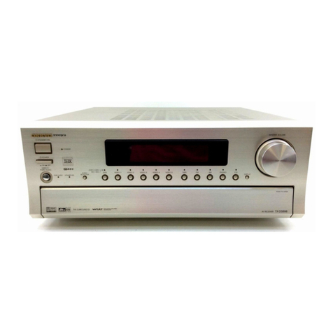
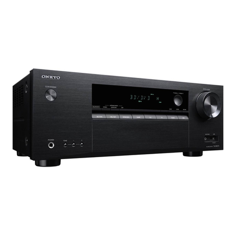
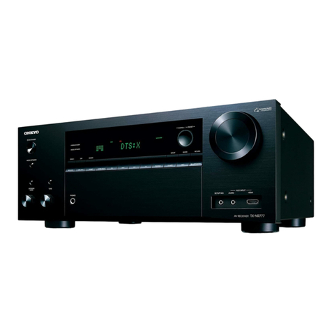
Onkyo TX-3000 User manual

SERIAL
NO.
3074
ONKYO.
SERVICE
MANUAL
SERVO
LOCKED
FM/AM
STEREO
RECEIVER
MODEL
TX-3000
1990
an
OX
Ct
D
model
G/W
model
POAQONONO
mm
ONE

TX-3000
SPECIFICATIONS
AMPLIFIER
SECTION
Output
Power:
45
watts
per
channel,
min.
RMS,
Signal-to-Noise
Ratio:
Mono:
70
dB
at
8
ohms
both
channels
driven,
Stereo:
65
dB
from
20
Hz
to
20,000
Hz,
with
Alternate
Channel
Att:
60dB
no
more
than
0.04%
total
AM
Suppression
Ratio:
52
dB
harmonic
distortion.
Harmonic
Distortion:
Mono:
0.15%
Total
Harmonic
Stereo:
0.3%
Distortion:
0.04%
at
rated
power
Frequency
Response:
30
Hz
—
15,000
Hz
(41.5
dB)
0.04%
at
1
watt
output
Stereo
Separation:
40
dB
at
1
kHz
IM
Distortion:
0.1%
at
rated
power
.
30
dB
at
100
Hz
—
10,000
Hz
0.04%
at
1
watt
output
Muting
Level:
14.7
dBf,
3
uV
Damping
Factor:
40
at
8
ohms
Stereo
Threshold:
14.7
dBf,
3
pV
Frequency
Response:
20
Hz
—
30,000
Hz
(+1
dB)
Servo
Lock
Level:
14.7
dBf,
3
pV
RIAA
Deviation:
Sensitivity
&
Impedance:
20
Hz
—
20,000
Hz
(+0.8
dB)
Phono:
2.5
mV,
50
kohms
Tape
Play:
150
mV,
50
kohms
AM:
Tuning
Range:
325
—
1,620
kHz
Tape
Rec:
150
mV,
3.5
kohms
Usable
Sensitivity
:
2)
wv
(PH)
|
Image
Rejection
Ratio:
45
dB
Phono
Overload:
180
mV
r.m.s.
at
|
kHz,
0.04%
IF
Rejection
Ratio:
30
dB
THD.
Signal-to-Noise
Ratio:
40
dB
Signal-to-Noise
Ratio:
Phono:
85
dB
(at
10
mV
input
Harmonic
Distortion:
0.8%
IHF
A
weighted)
GENERAL
_
65
dB
CHF
C
weighted)
power
Supply:
AC
120
volts,
60
Hz
(D
model)
Tape:
95
dB
(IHF
A
welgnen
AC
220
volts,
50
Hz
(G
model)
| |
90
dB
(IHF
C
weighted)
AC
220/120
volts,
50/60
Hz
Residual
Hum
&
Noise:
0.8
mV
at
Volume
Control:
min.
Tone
Controls:
Bass:
+12
dB
at
100
Hz
(W
model)
one
WONMTONS:
ss
;
+12
d
10
ki
Outputs:
Speaker
A
&
B,
Phones,
Tape
—_
Treble:
7
oB
at
10
kHz
Rec
Out
1
&
2,
AC
Outlet
(x
2)(D
model)
High
Filter:
6
kHz
(6
dB/oct)
Inputs:
Phono,
Tape
Play
|
&
2
Loudness
(—30
dB):
+9
dB
at
40
Hz
FM
and
AM
An
tennas
+5
dB
at
20
kHz
Antennas:
FM:
300
ohms
balanced
and
75
ohms
unbalanced
TUNER
SECTION
AM:
_
built-in
ferrite
core
FM:
antenna
and
external
Tuning
Range:
88
—
108
MHz
(D
model)
terminal
87.5
MHz
—
108
MHz
Semiconductors:
I
FET,
20
transistors,
11
ICs,
(G/W
model)
38
diodes
(D
&
W
model)
Usable
Sensitivity:
Mono:
11.2
dBf,
2
uv
1
FET,
22
transistors,
11
ICs,
Stereo:
19.2
dBf,
5
uV
38
diodes
(G
model)
50
dB
Quieting
Dimensions
(W
x
Hx
D):
480
x
130
x
376mm
Sensitivity
:
Mono:
17.2
dBf,
4
uV
19”
x
5-1/8”
x
14-13/16”
Stereo:
37.2
dBf,
40
uv
Weight:
11.4
kg,
25.1
Ibs
Capture
Ratio:
1.5
dB
Image
Rejection
Ratio:
60dB
Specifications
and
features
are
subject
to
change
without
notice.
IF
Rejection
Ratio:
85
dB
Spurious
Rejection
Ratio:
85
dB
COMPONENT
LOCATION
slowole
©)
|) \&
|G
©
Wht
Back
View

TX-3000
©
®
()
0
'
in
Top
View
COMPONENT
LOCATION-PARTS
LIST
31
27120200
Back
panel
(D)
D/W
model
27120202
Back
panel
(W)
RFF.
CIRCUIT
NO.
PARTS
NO.
DESCRIPTION
330143
FF-1S4.
Puseholdes(W)
;
(on
the
chassis)
l
13549581A
Aa
rec
ameter
mob
27300288
Switch
locked
plate(W)
2
13549583
NASW-783,
Switch
p.c.b.
25065109
—
NSS-2255P,
Voltage
selector
3
13549584
NADA-784,
Power
amplifier
switch(W)
(on
the
back
panel)
p.c.b.
7
G
model
4
13549586
NAAF-786,
Tone
amplifier
REF
p.c.b.
(D)
‘
CIR
13550586B
NAAF-786b,
Tone
amplifier
No,
CIRCUIT
NO.
PARTS
NO.
DESCRIPTION
p.c.b.
(W)
1
13552581
NARFE-781,
FM/AM
tuner
and
5
13549585
NAPS-785,
Power
supply
circuit
equalizer
amplifier
p.c.b.
p.c.b.
2
13549583
NASW-783,
Switch
p.c.b.
6
13549587
NAPL-787,
Meter
illumination
3
13549584
NADA-784,
Power
amplifier
lamp
p.c.b. p.c.b.
7
Q503,
Q603
222022
STK-00501,
Power
amplifier
IC
4
13552586A
NAAF-786a,
Tone
amplifier
8
T9O1
250350
NPT-696D,
Power
transformer
(D)
p.c.b.
250361
NPT-696DG,
Power
transformer
(W)
5
13552585A
NAPS-785a,
Power
supply
9
L152
232066
NMA-3012,
AM
bar
antenna
circuit
p.c.b.
10
C951
3500054
0.0luF,
125V,
CS
capacitor(D)
6
13549587
NAPL-787,
Meter
illumination
C951,C952
3500058
PME265MBS5
10,
IS
capacitor
lamp
p.c.b.
(Ww)
7
Q503,
Q603
222022
STK-O0050H,
Power
amplifier
IC
11
RS528,R628
441623314
3309,
1W,
Metal
oxide
film
8
TIO]
250351
NPT-696G,
Power
transformer
resistor
9
L152
232066
NMA-3012,
AM
bar
antenna
12
$706
25065016
NSS-2327,
Slide
switch
10)
C951
3500058
=
PME265MB510,
IS
capacitor
13
P804
25060008
Ground
terminal
1]
R528,
R628
441623314
3309,
1W,
Metal
oxide
film
14.
P80S
25060035
NITM-4PRMC06,
Antenna
resistor
terminal
12
S706
25065016
NSS-2327,
Slide
switch
15
P806,P807
25060038
NTM-4PRMNO9,
Speaker
13
P804
25060008
Ground
terminal
terminal
14
P805
25060035
NTM-4PRMC06,
Antenna
16
P9O01,
P9O2
25050032
S-16444-01,
AC
outlet
terminal
17.
W901
253099A
AS-UC-3,
Power
supply
cord(D)
15
P806,
P807_
=
25060038
+=NTM-4PRMNO9,
Speaker
253083
AS-CEE,
Power
supply
cord(W)
terminal
18
W90la
270025
SR-3P-4,
Strainrelief
(D)
17
W901
253083
AS-CEE,
Power
supply
cord
270280
SR-4K-4,
Strainrelief
(W)
18
W90la
270280
SR-4K-4,
Strainrelief
19
F501,F601
252014
4A-T,
Speaker
protection
fuse
19)
F501,
F601
252014
4A-T,
Speaker
protection
fuse
20
25050004
Fuseholder
20
25050004
Fuseholder
21
F901
252049
4A(ST-6),
AC
fuse(D)
(on
the
21
F901
252074
2A-SE-EAK,
AC
fuse
power
supply
p.c.b.)
F902,
F903
252078
S5A-SE-EAK
(on
the
power
252014
4A-T,
AC
fuse(W)
(on
the
supply
p.c.b.)
power
supply
p.c.b.)
22
27205021
Drive
shaft
22
PREEIET
Drive
shaft
*
23
27115058
Side
bracket
(R)
23
7115058
Side
bracket
(R)
24
27115059
Side
bracket
(L)
24
27115059
Side
bracket
(L)
25
27115060
Center
bracket
25
27115060
Center
bracket
26
27160062A
Radiator
26
27160062A
Radiator
27
270760A
Dial
drum
27
270760A
Dial
drum
28
273803A
SP-14A,
Spring
28
273803A
SP-14A,
Spring
29
273903
Stringing
29
273903
Stringing
30
273812
Spring
for
pointer
lamp
30
273812
Spring
for
pointer
lamp
31
27120201
Back
panel
(D)

TX-3000
EXPLODED
VIEW
DISASSEMBLY
Top
Cover
Remove
the
four
screws
(4)
holding
the
top
cover
and
side
bracket.
Remove
the
two
screws
(3)
holding
the
top
cover
and
back
panel.
Front
Panel
Remove
the
top
cover.
Remove
the
TUNING
knob.
Remove
the
five
screws
holding
the
front
panel
and
front
bracket.
Bottom
board
Remove
the
four
screws
(24)
holding
the
bottom
board
and
chassis.
Remove
the
four
screws
(25)
holding
the
bottom
board
and
legs.
Meters
Remove
the
top
panel.
Remove
the
two
screws
holding
the
lamp
bracket
and
front
baracket.
Dial
Glass
Remove
the
four
screws
holding
the
dial
glass
and
front
panel.
Notes:
The
dial
glass
has
been
mounted
by
applying
an
800
gr
torque
to
the
screws.
~
If
the
dial
glass
is
removed
during
repairs,
and
a
torque
driver
is
available,
apply
800
gr
torque
to
the
screws
when
replacing.
If
however,
a
torque
driver
is
not
available,
simply
tighten
the
screws
by
hand.
When
replacing
the
dial
glass,
insert
all
relevant
component
parts
(9-13)
in
accordance
with
the
exploded
view.
Pointer
Lamp
Remove
the
top
cover
and
front
panel.
SERVICE
PROCEDURES
Sensor
Switch
(SENSOR)
This
switch
enables
the
servo
lock
system
for
automatic
FM
tuning
to
be
matched
with
the
various
operating
con-
ditions.
Set
it
at
LOW
initially.
Switch
to
NORM
or
HIGH
if
the
TUNED
lamp
does
not
instantly
turn
off
when
you
touch
the
tuning
knob.
Power
Meter/Signal
Strength
Meter
When
the
tuning
is
not
being
operated,
this
meter
displays
the
level
of
power
applied
to
the
right
speaker
system.
The
instant
the
tuning
knob
is
touched,
the
meter
changes
to
display
the
signal
strength
of
the
radio
broadcast
being
received
at
that
moment.
Tune
a
station
so
the
needle
moves
as
far
to
the
right
as
possible.
De-emphasis
switch
(Only
W
model)
The
25
ysec/Normal
selector
switch
for
Dolby
FM
boad-
casts
is
located
on
the
front
panel.
The
50
ysec/75
psec
selector
switch
employed
in
the
W
(120/220V)
model
is
located
on
the
bottom
board.
When
shipped
from
the
factory,
this
switch
is
set
to
the
SO
usec
position.
For
use
in
75
psec
regions,
switch
over
to
the
75
usec
position.
Voltage
conversion
(Only
W
model)
This
set
may
be
set
to
operated
at
either
120V
or
220V
at
50Hz
to
60Hz.
This
voltage
selector
switch
is
located
on
the
back
panel.
If
a
voltage
change,
is
necessary,
remove
the
lock
plate,
switch
to
the
proper
voltage,
and
replace
the
plate.

EXPLODED
VIEW
—
PARTS
LIST
(W):
Only
12/220
V
model
D
model
REF.NO.
PARTS
NO.
1
28184071
2
28140020
3
834430062
4
838440083
5
13549121
6
28125076
7
834130062
8
28191050
~27270014
10
27300038A
11
86213010
12
870051
13
—870052
14
27267063
15
27267064
16
28320399
17
27180049
18
28320398
19
28320396
20
28320408
21
28320397
22
27170071
23
27175009
24
83
1130082
25
831130122
26
28140126
29
27185002A
30
27185006
31
27130192
32
13549131
33
28133023
34
28130087
35
27190065
36
27250039A
37
27250040A
38
28198527
39
25045018
40
243117
243129
4]
243118
243130
42
27130193
43
25030150
44
25035047
45
210078
47
15349599
PRECAUTIONS
Fuses
DESCRIPTION
Top
cover
4tx10x40,
Cushion
3STS+6BQ(BC),
Tapping
screw
4STB+8CQ(BC),
Tapping
screw
Front
panel
ass’y
(5,
6,
14,
15)
End
cap
3STS+6
BQ,
Tapping
screw
Dial
glass
Spacer
Special
screw
WN3x10FN,
Nut
10x3.5x1.5t,
Washer
LOx6x1.St,
Washer
Guide
for
power
switch
knob
Guide
for
push
switch
knob
Push
switch
knob
Spring
for
knob
Power
switch
knob
Volume
control
knob
Tuning
knob
Tone
control
knob
Bottom
board
T-C,
Leg
3STW+8BQ,
Tapping
screw
3STW+12BQ,
Tapping
screw
Cushion
DP-16N,
Dial
pulley
Dial
pulley
Bracket
Pointer
ass’y
Back
plate
Dial
plate
Holder
for
dial
plate
Lamp
case
(L)
Lamp
case
(R)
Facet
LJ-100-J,
Stereo
headphone
jack
NIND-05008117
(Pointer:
white),
Signal
strength
and
output
level
meter
NIND-0500S129
(Pointer:
Red)
NIND-0250S118
(Pointer:
White),
Center
meter
NIND-02508130
(Pointer:
Red),
Center
meter
Bracket
for
meter
NRS-144-40Y,
Speaker
selector
switch
NPS-111L12P,
Power
switch
PL12V0.03AW-4,
Locked,
Tuned,
and
Stereo
indicator
lamp
NAPL-799,
Dial
illumination
lamp
p.c.b.
(G):
Only
220
V
model
G/W
model
REF.NO.
PARTS
NO.
1
28184072
2
28140020
3
834430062
4
838440083
5
13549121
6
28125076
7
834130062
8
28191050
9
27270014
10
27300038B
11
86213010
12
870051
13
870052
14
27267063
15
27267064
16
28320399
17
27180049
18
28320398
19
28320396
20
28320408
21
28320397
22
27170071
23
27175009
24
831130082
25
831130122
26
28140126
29
27185002A
30
27185006
31
27130192
32
13549131
33
28133023
34
28130087
35
27190065
36
27250039A
37
27250040A
38
28198527
39
25045018
40
243117
243129
41
243118
243130
42
27130193
43
25030150
44
25035176
25035034
45
210078
47
15349599
(D):
Only
120
V
model
TX-3000
DESCRIPTION
Top
cover
4tx10x40,
Cushion
3STS+6
BQ(BC),
Tapping
screw
4STB+8CQ(BC),
Tapping
screw
Front
panel
ass’y
(5,
6,
14,
15)
End
cap
3STS+6BQ,
Tapping
screw
Dial
glass
Spacer
Special
screw
WN3x10FN,
Nut
10x3.5x1.5t,
Washer
10x6x1.5,
Washer
Guide
for
power
switch
knob
Guide
for
push
switch
knob
Push
switch
knob
Spring
for
knob
Power
switch
knob
Volume
control
knob
Tuning
knob
Tone
control
knob
Bottom
board
T-C,
Leg
3STW+8BQ,
Tapping
screw
3STW+12BQ,
Tapping
screw
Cushion
DP-16N,
Dial
pulley
Dial
pulley
Bracket
Pointer
ass’y
Back
plate
Dia]
plate
Holder
for
dial
plate
Lamp
case
(L)
Lamp
case
(R)
Facet
LJ-100-J,
Stereo
headphone
jack
NIND-0500S117(Pointer:
White),
Signal
strength
and
output
level
meter
NIND-0500S129
(Pointer:
Red)
NIND-02508118
(Pointer:
White),
Center
meter
NIND-02608S130
(Pointer:
Red),
Center
meter
Bracket
for
meter
NRS-144-40Y,
Speaker
selector
switch
NPS-111-L140,
Power
switch
(G)
NPS-121-L,
Power
switch
(W)
PL12V0.03AW-4,
Locked,
Tuned,
and
Stereo
indicator
lamp
NAPL-799,
Dial
illumination
lamp
p.c.b.
For
continued
protection
against
fire
hazard,
replace
only
with
same
type
and
same
rating
fuse.
Speaker
protection
fuse:
The
speaker
protection
fuse
is
located
on
the
back
panel.
Remove
the
screw
holding
the
fuse
cover
and
fuse
case.
Rating:
4A-T
(Parts
No.:
252014)
AC
fuse:
Remove
the
top
cover.
The
AC
fuse
is
located
on
the
power
supply
pc
board.
Rating:
F901
4A
(ST-6)
(Parts
No.:
252049)
(Only
120V
model)
F901
2A-SE-EAK
(Parts
No.:
252074)
(Only
220V
model)
F902,
F903
S5A-SE-EAK
(Parts
No.:
252078)
(Only
220V
model)
F901
4A-T
(Parts
No.:
252014)
(Only
120/220V
model)
F902
2.5A-T
(Parts
No.:
252025)
(Only
120/220V
model)
(on
the
chassis)

TX-3000
ALIGNMENT
PROCEDURES
INSTRUMENTS
REQUIRED
GENERAL
ALIGNMENT
CONDITIONS
1.
DC
Voltmeter
1.
Signal
input
should
be
kept
as
low
as
possible.
2.
AM
Sweep
Generator
2.
Standard
modulation
is
400Hz
30%
(AM),
1kHz
100%
3.
AM/FM
Signal
Generator
(FM
MONO),
pilot
9%
sub
and
main
91%(FM
STEREO).
4.
AC
VIVM
3.
Standard
knob
position
5.
Oscilloscope
SPEAKERS
........-....-2222200250200
23s
A
6.
Monitorscope
BASS,
TREBLE
&
BALANCE
............
Center
7.
Distortion
Analyzer
HIGH
FILTER..............-..22-
0005
OFF
8.
Stereo
Modulator
MODE
.............
020200
e
teenies
STEREO
9.
Frequency
Counter
DE-EMPHA
..............-.-.....
NORMAL
LOUDNESS...
ee
ee
es
OFF
MUTING
LOCK
...................-5..
OFF
TAPE
1,2............0
00
eee
OFF
(SOURCE)
(1)
AM
IF
ALIGNMENT
1.
Set
SELECTOR
switch
to
AM.
2.
Set
radio
dial
to
quiet
point.
AM
Sweep
)
Orton
455kHz
X15]
Maximum
Symmetrical
Usually
not
necessary
Response
to
adjust
(2)
AM
RF
ALIGNMENT
Loop
Antenna
Bar
Antenna
=
AM
Signal
60cm
—
\
Output
|
|
aM
Sil
[4
XL
Unit
AC
VTVM
Oscilloscope
Lower
end
L153
Maximum
eee
eee“)
us
|
sn
Repeat
steps
|
and
1680kHz
Upper
end
TC152
Maxi
2
as
necessary
400Hz
30%
(1680kHz)
axmarn
600kHz
,
1400kHz
,
(3)
FM
FRONT
END
ALIGNMENT
1.
Set
SELECTOR
switch
to
FM.
2.
Connect
FM
Signal
Generator
to
300—ohm
antenna
terminals.
TP
Repeat
steps
3
and
4
as
necessary

|
Oscilloscope
unit
[~Jacvrvm
pL
Distortion
Analyzer
os
Pees,
[ose
[vem
ef,
[ee
Prwrsow]
SM"
fa
Maximum
98MHz
65dBf
Distortion
,
(4)
MULTIPLEX
ALIGNMENT
Repeat
Steps
1
and
2
as
necessary
pe
Tuning
Indicator
Repeat
Steps
3
and
4
as
necessary
fp
AC
VTVM
or
Oscilloscope
Repeat
Steps
5
and
6
as
necessary
EXT.
mod.
Connet
AC
VTVM
across
SPEAKER
terminals
L
Stereo
FM
Signal
|
300—ohm
ae
AC
VIVM
8—ohm
FM
Signal
Generator
|
Stereo
Modulator
Output
Indicator]
Adjust
for
98MHz
Frequency
H
R206
19000+19Hz
STEREO
INDICATOR
should
light
up
when
stereo
program
is
being
received.
Pilot
Sig.
9%
AC
VTVM
as
cerBe
EXT.
Mod.
|
Main
&
Sub
Sig.
|
98MHz
R202
Right
ch
Maimum
|
1KHz
Lch
91%
.
|
Left
ch.
necessary
Main
&
Sub
Sig.
1KHz
Rch
91%
4
Same
as
above

O
T.P
(IF
IN)
FM
IF
AMP.
&
DETECTOR
©
FM
tc
TC
TC
1C151
TC
DET
152
003
002
001
T101
L153
R206
AM
AM
IF
ose
M
PX
DECORDER
0
T.P(V.C.O)
T151
AM
DET
(+)
R202
SEP
L202
L201
LOW
PASS
FILTER
STRINGING
DIAGRAM
1.
Close
the
variable
capacitor
complete
and
tie
the
dial
cord
to
the
spring
of
the
drum.
2.
Thread
the
dial
cord
in
the
direction
of
arrow
from
(1)
to
@)
and
wind
the
dial
cord
three
turns
around
the
tuning
shaft
clockwise.
3.
Thread
the
dial
cord
©)
and@).
4,
Wind
the
dial
cord
1%
turns
around
the
dial
drum.

IC
BLOCK
DIAGRAM
HA-1137
BLOCK
DIAGRAM
LA3350
BLOCK
DIAGRAM
LAMP
DRIVER
STEREO
INDICATOR
TUFF
290°
1SKHz
PC
L-:
Phase
Comporator
tor
Lamp
LPF
Low
Pass
Filter
PC
¥
Phase
Comparator
tor
VCO
¥CO
TUF
Voltage
Controlled
Oscillator
F:
Direct
Coupted
Type
Flip-tlop
Substrate
Substrate
Out
put
HA-1151
EQUIVALENT
CIRCUIT
NJM4558D,
4559DX
STK3062
STK-005011

TX-3000
PRINTED
CIRCUIT
BOARD-PARTS
LIST
(D/W
model)
FM/AM
TUNER
AND
EQUALIZER
AMPLIFIER
PC
BOARD
(NARFE-781la)
—
PARTS
LIST
CIRCUIT
NO.
PARTSNO.
DESCRIPTION
ICs
C304,
C404
352721019T
100uF,
6.3V,
Elect.
O18!
533418
HeTtSt
C309,
C409
392880227T
2.2uF,
50V,
LL
0201
322449
LA3350
C311,
C312
352780339T
3.3uF,
SOV,
Elect.
0301,
Q401
222534
NJM4559DX
C702
3$2780109T
luF,
SOV,
Elect.
Q701.
922465
NIM4558D
C703
352742209T
22uF,
16V,
Elect.
C706
352784799T
0.47uF,
50V,
Elect.
Transistors
C707
352741009T
10uF,
16V,
Elect.
:
C708
352784799T
0.47uF,
50V,
Elect.
6002
soliede
SSC7RSTALOCONK)
C709
352732209T
22uF,
10V,
Elect.
0003
2211342
2SC461(B)
C710
352744709T
47pnF,
16V,
Elect.
9211723.
Or
2$C1923(R)
or
C713
352742219
220uF,
16V,
Elect.
1710823
3$C1675(L-1)
C714
352741009T
1OuF,
16V,
Elect.
Q202
2211256
2SC1815(BL)
Resistors
Q203
2211256,
2SC1815(BL),
-_
Q702~Q704
2211255
or
—
2SC1815(GR)
or
R202
3225024
NIOHRIKBD,
Semitixed
contro!
variable
Diodes
Switch
DOO]
223110
182687
D151,D153.
—-
223105
181555
D152
4000022
VD1212
Terminals
Bay
p02
IS1959
P801
25045020
-—-
NPJ-4PDBL11,
Phono/
-
Tape
rec.
2
223943
RD4.7EB
Tape
pb.
2
Coils
Shielded
case
LOOL
233106
or
NFA-3009
or
27225029
233088-1
FFA-3001
Shielded
plate
L002
233112
NFRF-3008
371
L003
233113
NFRF-3009
50085
L004
233152
NFT-1503
L00
L102
233090
NFO-3003
POWER
AMPLIFIER
PC
BOARD
L103.
233114
NCH-1009
(NADA-784)
—
PARTS
LIST
L151
233152
NFT-1503
CIRCUIT
NO.
PARTSNO.
DESCRIPTION
L153
232065
NMO-2002
ICs
L201,
L202
233021
or
NMC-8-5
or
233107
NMC-5002
35)
;
ea
222023
STK3062
NJM4558DX
Transformers
,
Q503,Q603
222022
STK-00501
TOO!
233085
NIT-0518
,
T101
233101
or
NFIF-6003
or
Transistors
233083
NIT-3516
Q751,Q752
2211544
28C1959(Y)
T151
232041
NIT-0509
Q903,
Q904,
=
2211255,
2SC1815(GR),
C
e
filt
Q906
2211256
or
28C1815(BL)
or
X101,
X102
3010003
SFE-10.7MA
Q905
2211455
or
2SA1015(GR)
or
X15]
3010004
CFZ-455C
2210803
2SA733(P)
Capacitors
Diodes
VCO01~VC004
3050006
NVC-20FQ327WD02,
Variable
DS01,D502,
223105
181555
TC004
3060003
NTC-10P02,
Trimmer
D601,
D602
C021
352741019T
100uF,
16V,
Elect.
D751~D754,
223103
or
1N60
or
C106
352750479T
4.7yF,
25V,
Elect.
D737
223132
1K60
C108
352741009T
10yF,
16V,
Elect.
D7553,D756
=
233119 1$1588
C109
352782209T
22uF,
SOV,
Elect.
D908
223848
or
GP-08B
or
C118
352750339T
3.3uF,
25V,
Elect.
223804
SR1K-2
C153
372523614
360pF+5%,
SOV,
ST
D909,
D910
=
233105
181555
C158
352741009T
10yF,
16V,
Elect.
Capacitors
C159
352742219
220uF,
16V,
Elect.
C162
352780109T
1uF.
SOV.
Elect.
C501,C601
352780339T
3.3uF,
SOV,
Elect.
C163
352780339T
3.3uF,
SOV,
Elect.
C506,
C606
352780109T
luF,
SOV,
Elect.
C165
352721019T
=
100uF,
6.3V,
Elect.
CS10,
C511,
352780479T
4.7uF,
SOV,
Elect.
C201
352744719
470uF,
16V,
Elect.
C610,
C611
C202
352780109T
iuF,
SOV,
Elect.
C513,
C514
392852207T
22uF,
25V,
LL
C203
352741009T
10uF,
16V,
Elect.
C613,
C614
C204
392883397T
0.33uF,
50V,
LL
C516,
C616
352780339T
3.3uF,
SOV,
Elect.
C205
392882297T
0.22uF,
50V,
LL
C751,
C752
352780229T
2.2uF,
SOV,
Elect.
C206
392884797T
0.47uF,
50V,
LL
C753,
C754
352781009T
10uF,
50V,
Elect.
C207
372521524
1,500pF+5%,
50V,
ST
C921
352753309T
33
uF,
25V,
Elect.
C209
352780339T
3.3uF,
50V,
Elect.
C922
352722219
220uF,
6.3V,
Elect.
C211,
C212
352781099T
0.1uF,
50V,
Elect.
C301,
C401
352780229T
2.2uF,
50V,
Elect.

Resistors
C362,
C462
352780109T
luF,
50V,
Elect.
C375,
C376
3§2754719T
470uF,
25V,
Elect.
R507,
R607
451730104
12, 2W,
Metal
°
,
,
R508.
R509,
4000047
0.4792,
5W,
Metal
plate
C377,
C378
352750339T
3.3
uF,
25V,
Elect.
R608,
R609
Resistors
R751,
R752
§225018
NIOHRIKBC,
Semi-fixed
R757,R758
441621224
1.2,
1W,
Metal
oxide
film
R361,
R461
5148038
Pree
net
OOK
C040,
Coil
Bass
control
variable
R371,
R471
$146017
N16RLC1OOKWTP40,
L501,
L502
231001
S-1.3B
Balance
control
variable
Relay
R375
441623314
3302,
1W,
Metal
oxide
film
RLIOI
2506S5085A
NRL-2P5A-DC1
2-03
Switches
25035174
NPS-522-L138,
High
filter/
POWER
SUPPLY
PC
BOARD
(NAPS-785)
—
PARTS
LIST
CIRCUIT
NO.
Q901
Q902
D901~D904
D905~D907
C905,
C906
C907,
C908
C910
Corl
C912
C913
R901
R902
R904
F901
PARTS
NO.
Transistors
2201075
or
2201074
2211256,
2211255
or
2210746
Diodes
223863
223848
or
223804
Capacitors
3504125
352762219
352751019
352752229
352744709P
352741019P
Resistors
441623314
441623014
431530564
Radiator
27160011A
Fuseholder
250113
Fuses
252049
DESCRIPTION
2SD880(Y)
or
2SD880(GR)
2SC1815(GR),
2SC1815(BL)
or
25C945(A)P
GP-30DL
GP-08B
or
SR1IK-2
12,000uF,
50V,
Elect.
220uF,
35V,
Elect.
100uF,
25V,
Elect.
2,200uF,
25V,
Elect.
47uF,
16V,
Elect.
100uF,
16V,
Elect.
3302,
1W,
Metal
oxide
film
3009,
LW,
Metal oxide
film
5.69,
1/2W,
Metal
Radiator
SN5051
4A
(ST-6)
TONE
AMPLIFIER
PC
BOARD
(NAAF-786)
—
PARTS
LIST
(D
model)
CIRCUIT
NO.
Q351,
Q451
D375,
D376
C353,
C453
C356,
C456
C361,
C461
PARTS
NO.
IC
222534
Diode
224072
or
224000
Capacitors
392880227T
392880107T
352742209T
DESCRIPTION
NJM-4559DX
BZ-177
or
RD-18FB
2.2uF,
50V,
LL
igF,
50V,
LL
22uF,
16V,
Elect.
Mode/Loudness/FM
muting/
De-emphasis
TONE
AMPLIFIER
PC
BOARD
(NAAF-786b)
—
PARTS
LIST
(W
model)
CIRCUIT
NO.
PARTS
NO.
DESCRIPTION
Ic
Q351,
0451
222534
NJM-4559DX
Diode
D375,
D376
224072
BZ-177
Capacitors
C353,
C453
392880227T
2.2uF,
50V,
LL
C356,
C456
392880107T
luF,
50V,
LL
C361,
C461
352742209T
22uF,
16V,
Elect.
C362,
C462
352780109T
luF,
SOV,
Elect.
C375,
C376
352754719T
470uF,
25V,
Elect.
C377,
C378
3$2750339T
3.3uF,
25V,
Elect.
Resistors
R361,
R461
$148038
N16RGM11CI00KCO40,
Treble
control
variable
R366,
R466
5148039
N16RGM11C100KCS40,
Bass
control
variable
R371,
R471
§146017
N16RLCIOOKWTP40,
Balance
control
variable
R375
441623314
3302,
1W,
Metal oxide
film
Switches
25035174
NPS-522-L138,
High
filter/
Mode/Loudness/FM
muting/
De-emphasis
250142
NSS-2225,
De-emphasis
METER
ILLUMINATION
LAMP
PC
BOARD
(NAPL-787)
—
PARTS
LIST
CIRCUT
NO.
PARTSNO.
DESCRIPTION
PL803~PL805
2100548
PL6.3V,
0.25A,
Pilot
lamp
DIAL
PLATE
ILLUMINATION
PC
BOARD
(NAPL-799)
—
PARTS
LIST
CIRCUIT
NO.
PARTSNO.
DESCRIPTION
210054A
PL6.3V,
0.25A,
Pilot
lamp
NOTES:
1.
DC
voltage
are
measured
with
V.T.V.M.
to
chassis
at
no
signal
applied.
2.
Capacitor
LL:
Low
leakage
current
type
electrolytic
capacitor
ST:
Polystyren
film
capacitor
TONE
AMPLIFIER
PC
BOARD
VIEW
FROM
BOTTOM
SIDE
(D
model)
-
O
RAST
a?
oO
Oo
oO
eit?
,
wf.
4
+e
wa
Ri6?
—
mg
i859
R366
R&66
ae
BASS

SCHEMATIC
DIAGRAM
MODEL
TX-3000
D
1SP
(CH)
BES
PLB06
12V0.03A
LOCKED
LAMP
(568
0102
o7Tos
1SI555
1S
1555
PL807_12V0034
TUNED_LAMP
ALTE
GRorBL
PL8O8
12V0.03A
STEREO
LAMP
+0158
=}
1076
DIS3
ISISSS
Many
aoe
$7020
S702b4
12
.
MUT/ILOCK
R762
RII
560
¥
5
6k
NMC
-5002
QIS!
HAUS!
-1100/6.3
aM
SECTION
REC-1
:
co
Q704
|
|
|
a
PLAY
-
y
$8024
S80la
C226
H
ow
my
k-
ca02
a047
TU/PH
FM/AM
re
|
:
. : .
gta
iF
le Oo
OQ
<eeaaees
s
aE)
7
REC
2
300
(IW
85)
jaaiade
i
ae
‘Pook
NADA-784]
i
ease
Ae
0375_
[Nan
3
7
E
dee
82-177
Gz
:
$303
eS
peo
or
RO-I¢FB
cs01
Rs02
3
7
L1n
23750.
330
&
7
:
Y 0
co
38S
SP
5
R501
CSc2
|
$RS03
C362
R369
a
°
{
10/50
47K
a
470K 100P
58K
3359
IM
re
cae
C506
Joe
C361
F
50086
|
h
R520
1.07
#3
56K
22/16
=F
aan
2
RY
i
1K
PLAY-2
|
Qran
“
|
:
Ite.
R365
2
|,
v
R517
a
pena
ci
a
4
Sp
HI-FIL.
oF
R376
300(1W)
ae
fee
Petia
o!
$704b
e378
e376
D376
a
|
;
Og,
MODE
ais
cas
az-i77
diate
a
or
R371
100K
W
a
RO-i8
FB
BAL.
:
’
.
PHONO-
RE
belt
Q301(Q401)
Y
NJM-45590X
PHONO-R
.
Cc
cao
TONE
AMP,
TONE
CONTROL
'
$7036
s70sb
bf
:
.
LOUDNESS
=©9351(0451)
NUM-45S59DX
HI-
FIL.
nee:
ee
||
ee
|
$901
POWER
[]
2-OFF
S$80la~d
SELECTOR
tas
2-AM
976
$
(IGG
5-2
ot
8
(9)
$802a0~d
SELECTOR
UNER]
2-PHONO
$803a,b
T.
MONI
lente
URCE}
2-TAPE-|
$804a,b
T.MONI
RCE]
2-TAPE-2
5TK-3062
$810a,b
SPEAKER
T-OFF)
2-A
3-B
4-A+B
1236
bo2
3--------
78)
$701a,.bDE-EMPHA
_—[[-
781]
2-25yS
056
ecs
pce
eae
HH
$702a,bMUTE/LOCK
([{[-ON]
2-OFF
8
€
Teneesee
ar
rae
sedee
$703
4,b
LOUDNESS
|_2-
ON
2SKI9TM
2SC785TM
2SAI0I5
2SC46!
2s0880
NJM-4558
HAII37
S704,
b
MODE
2-MONO
2SC1923
2SA733
NJM-4559
HAIIS1
STK
-3062
STK-O050I
$7050,b
HI-FILTER
Tilda}
2
ON
ORAIAL
2SCi8I5
2SC945
LA2350
No
S706
|
SENSOR
GH
3-LOW
2S8C
1959
NARFE-761a
|
NASW-783|
"Q101
2801923
Dork
clos
116
QIOZ
HAIISTW
SENSOR
AME
FM
FRONT
END
aia
|
$702,
R701
,
KNOB
=
DIAL
LAMP
METER
LAMPS
Nein
LAMP
[ra
nf
[NAPL-TOS|
[NAPC“767]
"tae
see
Q701
ale
KNOB
MERE
aoe
NERF
703
val
NJM-4558D
R702
|
C70!
;
Piso
*
PL8O3
PLOL
PLBCS
»
PL8O9
hee
(9.
‘D702
¢
1M
0.0022
6.3V0,25A
63V0.25A
63VQ25A
6.30254)
oa
Pee
‘Weasa
orRO-4.7E8
|
1S1555
nso
=
|
SENGOR
ag
SE
|
sere]
TE
i
i
1716
FF
39K
703
Ot
deo
es
-_
His
R703
|
me
:
0,022
goo
2skiatw-cr
'%
¢™
p70!
ore
80
002
2SC78STM-0
IS1855
:
cooe
Roa
}
cor
:
T-METER
J
Q003
2804616
ap
ec2
x)
Soe?
see
ae
paietom
tds
:
.
wer
Ais
oy
tow
{ita
|
TUNING
METER
NAPS
785.
5
9010904
GP-300L
'
eat
Le
3
ROOD
COIS
OP
coe
ROO
ae
RI2
{S00
7K
SP(TH)
yeopg
[
ICH)
Le
0072
;
NA
B///
>
y/
2003
1
3
cast
5}
RS
0.017125V
[U..
r—]
C902
7
735
001
/500V
F901
4a
(ST-6}
AC
l20V
60Hz
f
tH
WOOWMAX
I00WMAK
Evol
raw
cats
H
POWER
&
SIGNAL
METER
=
0.01/
500V
jcsio
gg
D905~D907
|
‘foosy-
GPp-68B
or
SRIX-2
|
Faso!
2soesoyverGr
°2!
0902
2SCIBISGRorGR
or
2S8C945AP
INGO
R752
1KBC
C754
J°
METER
10/54
°T-
C922
220/63
|
Oo
9
|
zu
Ae.
2?
m
n
047)
RSI0
(SW)
.7(172w)
R50
csi
22/25
2806
SPZAKER-A
RSI2
ISK
7407
SFEAKER-B
(RL901)
Sok
Qs01(Q60!)
STK-3062
an
Q502.q602
NJM-45580X
Q503.9603
STK-O0SOT
NOTES
CALL
RESISTORS
ARE
IN
OHMS,
'%
WATT
UNLESS
OTHERWISE
NOTED.
CALL
CAPACITORS
ARE
IN
wF,
SOWV
UNLESS
OTHERWISE
NOTED.
CELECTROLYTIC
CAPACITORS
(—#—)
ARE
IN
JF/
WV.
o
VOLTAGE
(MEASURED
WITH
V.T.V.M)
(NO
INPUT
SIGNAL).
eCIRCUIT
IS
SUBJECT
TO
CHANGE
FOR
INPROVEMENT.
ONKYO
CORPORATION
TX-3000

SCHEMATIC
DIAGRAM
MODEL
TX-3000
G
NARFE-781
|
NASW-783]
|
“QO
2SCI9Z300R
Coa
torte
>
rae
So
aaaae
2
or
2SCI675L-1
Ee
IOs
MAN
eT
SENSOR
AMP.
|
FM
FRONT
ENO
vay
C72
7M
KNOB
=
OIAL_
LAMP
METER
LAMPS
ane
DIAL
LAMP
é
‘3
INTER
-|O°
poe
wt
7—Wcee
—(_)
_
[RAPL-7S9
[NAPL-767]
~~
|"Lawe
"
NAPL799]
Tee
D703
NJM-45580
R702
|
C701
PL801
7
;
PL8O3
PLSOL
PLBOS
4
PLOOO
|
PLAC2
YZ-047
D702
IM
s500022
|
si0e
6,340.25
G3VO2SA
63VOZAGIMSAl
EIVOOSA
|
6.
3VO75A
or
RO-4.7EB
181555
6.750
if
SENSOR
SW.
ny}
0
m2
2
ANZ
820
1
{
i)
+
xto8
SFE-10,7MA\
0.022
=
+o
SENS
C707
+
R706
a)
e303
fa
er
ss
.
716
FF
39K
22/16
$R703
P!
pari
10K
:
2.7K
Lalo
:
me
au
—|O
eoot
2ski9Tw-cr
'™
corm
|
Ti
9)
p7ol
£704
001
4
Q002
2SC78STM-O
—
-
4
1$1855
:
@003
28C4618
cod
ROIS
2
C013
ob
Oz!
ge
ea
tele
a
——
£009
Re
er
Rize
R78
Te
:
ee
Ste
et
en
ee
,
190!
isp
R00
da
iM
M102
APS-7690]
p90in0904
GP-300L
FUSE
;.,
fail
deg
017
TUNING
METER
R09
COIS
OP
cols
Mpg
Fa0z
3001
A
47K
SPITH)
yoo,
(CH)
70022
= =
ain
wl
tT
TQ
KC)
2003.
AP
///7
0022
ara
‘Ws
na
Al
ROW
C020
eee
.
ROW
000!
WOK
PISPICH)
fic
1K
|:
*igogar
ISPs
AOI2
3.3K
;
PLBO6
12V0.034
¥
Meter...
Se
ploz
sé
708
LOCKED
LAMP
Te
ee
181588
=
!
ee
aene
ard
ame
=
Sexe
M
2Sclai5
R209
ae
vane
\
Poe
AC
220V
GR
or
ane
Cy,
THERMO
0617250V
5SOHz
\FUSE
by
PLBOB
12V0.034
7
sie
STEREO
LAMP
F205
Js
iam
33/50
"T-
ese
6
9202
T
woe
qpescisiser
ti
\
X
s702a
$7020)
Co
C210
ee
M
rea
Y
Wes?
md
wut
cock
|
R223
3.3K
Clég
9022
+H
3
C219
0.33/50
i
g15s
~~
eces
Q15!
HAIISI
“1100/6.3
aM
SECTION
$802
TU/PH
Q205.9206
28C2240GRorBL
Te
or
2SCIGS4F
ore
25clevsener
BL
or
280
945AP
$8020
$80la
TU/PH
FM/AM
C358
SP
C362.
R369
10/50
47K
bo
pace
be
$705a
cee
0067
HLFIL.
©
Bits
20011)
°
!
>
a
&
PLAY-|
O
rae
RSS
H
a3a77
15K
qui
a
1
26
id
oO"
$70
ab
cis
ok
a7
|
D376
OT
5,
MODE
33725
ins
-I7
:
|
eee
QO
ai
2
Seer
R371
100K
W
alti)
oo
RD-ISFB
alr
1
lecin
re
.
PHONO-L
eh?
3
!
case
Gi?
Q301(0401)
a
°
oa
4
NJM-
45590X
je
R
R
2
2
!
|
|
$703b
s705b
:
P
..
©
LOUDNESS
=—»-.Q.351(0451)
NuM-45590X
HirFIL.C,
#e
|
=
1
|
6
PHONO-R
TONE
AMP,
TONE
CONTROL
:
!
[
csdl
P
$901
POWER
TON]
2-
|
*
$e@0la~d
SELECTOR
876
5
NB)
1h
2
ee
een
anne
8
(9)
$602a~d
SELECTOR
$8030,b
T.MON!
$80420,b
T.MONI
pid
ial
SPEAKER
123
4
2
Pieenes
~-
718}
STO!
0,
b
OE-EMPHA
3
6
ece
(Tor
view)
(Top
VIEW)
$702
a,
b
MUTE
/LOCK
Qanwnnn9
0
$703
4,
b
LOUDNESS
2SKI9TM
2SC7BSTM
2SAI0I5
2SC46)
250880
NuUM-4558
HAII37
STO4o,
b
MODE
preter
Pani
NJM-4559
HAII5!
STK-O0501
$706
SENSOR
Z5cee40
osc
1959
1
139*
104
L----H+
sot
POWER
ae
{
C315
POWER
&
SIGNAL
METER
d
0.01/500V
;
cao
ff
4399050907
100257-
GP-088
or
SRIK-2
Hasof
2spssoyverGR
“8/5
isl
|
2902
2SCI8ISGRer
GR
|
or
2SC945AP
5
1
it
lassi
as
‘281959
i
See
aera
2SCISISGR
or
8
mee
R757
1KBC
C754
ye
or
28C945AP
oss
METER!
:
ADJ.
0754
:
INGO
|
0756
isisee
|
Psos
R528
sre
a
|
PHONES
R628
330
11
W)
R508
0.47
S10
SW)
4707}
(RL9O1}
Td
a
P806
SPEAKER-A
e|
FUS
3
Soe
2
zt
4A
g
ott
P07
ee
aye
SPEAKER-B
-
Za
L
ch.
RSI3
18K
rs
he
|
SPEAKER
SW.
(RL901)
Rech
QS501(Q60!)
STK-3062
7
Q502.Q602
NUM-45580X
Q503.Q603
STK-0050]
NOTES
CALL
RESISTORS
ARE
IN
OHMS,
4
WATT
UNLESS
OTHERWISE
NOTED.
©
ALL
CAPACITORS
ARE
IN
wF,
SOWV
UNLESS
OTHERWISE
NOTED.
OELECTROLYTIC
CAPACITORS
(—#—)
ARE
IN
pF/
WV.
o
VOLTAGE
(MEASURED
WITH
V.T.V.M)(NO
INPUT
SIGNAL).
CCIRCUIT
IS
SUBJECT
TO
CHANGE
FOR
INPROVEMENT.
ONKYO
CORPORATION
TX-3000

TX-3000
TONE
AMPLIFIER
PC
BOARD
VIEW
FROM
BOTTOM
SIDE
(G/W
model)
MPX
€
LOUDNESS
—E
+
19
3
E
0
0
bo
—_
b
0
6060000
wi
_
000
Hoo?
woe
RB
RA
E—
1A
L
36
a
XL
wo
a
ip
ae
RF
J
wn
aL
ot
oo
rs
IN
=
R377
&
©
O]O
~17.7V
fr
cope
17-7
¥
Tye
ef
RL52
fad
O
nm
Ling
ra’
mi
OF
oR
ir
R355
.
q
Glo
iB
vere
a
“tk
~™
§.LOCK
a
AAA
———
n
e
3
wi
2
:
T
©
Tg
8352
a
5
gi
T
+,
-
s
g
ny
353
33
wa
2389
c362
8
ne
yo351
oO
O
CL6t
+,
4
—__—_—_-
C462
|
—Hg-
R465
8
C225
R469
a)
REO
—_A—
o
:
Tt
ar
i
C458
Wha
a0
Br
uw
wo
~
w
te
a”
z
“Le
R360
C226
R73
Cu56
a
iS
38?
ae
6380
“
a
S
ao
C358
yy
238?
a
s
BS
rr
yy
R82
Z
g
oy
446459
C359
=
Zz
au
=
—
_
446460
a
=
re
ae
S
ss
CAB,
pes
ay
Ribs
onphst
Pe
=
|
oo
“
a
R371
BALANCE
TREBLE
BASS
PRINTED
CIRCUIT
BOARD-PARTS
LIST
FM/AM
TUNER
AND
EQUALIZER
AMPLIFIER
PC
BOARD
(NARFE-781)
—
PARTS
LIST
CIRCUIT
NO.
PARTS
NO.
ICs
Q102
222421
QO151
222418
Q201
222449
QO301,
Q401
222534
Q701
222465
Transistors
Q001
2211815
Q002
2211845
Q003
2211342
Q101
2211722,
2211723
or
2210823
Q202
2211256
Q203
2211256,
Q702~Q704
2211255
or
0706
~Q708
2210746
Q205,
Q206
2211405,
2211406,
2211732
or
2211733
Q705
2211256
Diodes
DOO1
223110
D101,
D102
223105
D151,
D153
223105
D152
4000022
D202
223105
D701,
D702
D704~D708
D703
224011
or
223943
Coils
LOoOo1
233106
or
233088-1
LOO2
233112
L003
233113
L004
233152
LOO5
233090
L101,
L102
233105
L103
233114
L151
233152
L153
232065
L201,
L202
233126
DESCRIPTION
HAIL137W
HALIS1
LA3350
NJM4559DX
NJM4558D
2SK19TM-GR
2SC785TM-O(ONK)
28C461(B)
28C1923(O),
2SC1923(R)
or
28C1675(L-1)
28SC1815(BL)
2SC1815(BL),
28SC1815(GR)
or
2SC945(A)P
2SC2240(GR),
28C2240(BL),
28C1845(E)
or
2SC1845(F)
2SCI815(BL)
182687
1S1555
1S1555
VD1212
IS1L535
YZ047
or
RD4.7EB
NFA-3009
or
FFA-3001
NFRF-3008
NFRF-3009
NFT-1503
NFO-3003
NCH-1005
NCH-1009
NF
T-1503
NMO-2002
NMC-5008
TOOL
TILOL
T151
X102,
X102
X151
V¥C001~VC004
TCO04
C021
C106
C108
C109
C118
C133
C158
C159
C162
C163
C165
C201
C202
C203
C204
C205
C206
C207
C209
C211,
C212
C215,
C216
C219,
C220
C301,
C401
C304,
C404
C309,
C409
C311,
C312
C702
C703
C706
C707
C708
C709
C710
C711
C713
C714
R202
R206
R356,
R456
Transformers
233085
233101
or
233083
232041
Ceramic
filters
3010003
3010004
Capacitors
3050006
3060003
352741019T
352750479T
35274
1009T
352782209T
352750339T
372523614
352741009T
352742219
352780109T
352780339T
352721019T
352744719
352780109T
35274
1009T
392883397T
392882297T
392884797T
372521524
352780339T
352780109T
392883397T
3$2780229T
3$2721019T
392880227T
352780339T
352780109T
3$2742209T
352784799T
35274
1009T
352784799T
3$2732209T
352744709T
352721019T
352742219
352741009T
Resistors
$225024
5225019
5148042
NIT-0318
NFIF-6003
or
NIT-3516
NIT-0509
SFE-10.7MA
CPZ-455C
NVC-20FQ327WDO2,
Variable
NTC-10P02,
Trimmer
100uF,
16V,
Elect.
4.7uF,
25V,
Elect.
10uF,
16V,
Elect.
22uF,
50V,
Elect.
3.3uF,
25V,
Elect.
360pF+5%,
50V,
ST
10uF,
16V,
Elect.
220uF,
16V,
Etect.
lyF,
50V,
Elect.
3.3uF,
SOV,
Elect.
100uF,
6.3V,
Elect.
470uF,
16V,
Elect.
luF,
50V,
Elect.
10uF,
16V,
Elect.
0.33uF,
50V,
LL
0.22uF,
SOV,
LL
0.47uF,
50V,
LL
1,500pF+5%,
50V,
ST
3.3uF,
SOV,
Elect.
Luk,
SOV,
Elect.
0.33uF,
50V,
LL
2.2uF,
50V,
Elect.
L00uF,
6.3V,
Elect.
2.2uF,
SOV,
LL
3.3uF,
50V,
Elect.
LuF,
SOV,
Elect.
22uF,
16V,
Elect.
0.47pF,
SOV,
Elect.
10uF,
16V,
Elect.
0.47uF,
50V,
Elect.
22uF,
1OV,
Elect.
47
uF,
16V,
Elect.
100uF,
6.3
V,
Elect.
220uF,
16V,
Elect.
10uF,
16V,
Elect.
N1OHRIKBD,
Semi-fixed
N1OHR4.7KBD,
Semi-fixed
NI6RGLIOOKBTP40,
Volume
control
variable

BLOCK
DIAGRAM
ANTEMHA
o00t
goo,
=
«1081,
xD
gtgT
tz
TFT
le
ls
Ie
202
MUTING
SW
amr
TR
AMP,
MUTING,
[&
DET,
S.
METER,
AFC]
T.METER
7
Fy ha
ny
ae
80%
ani
¥u/S
METER
(
pees
Siw.
ari
nec-1
ad
aos
r
:
Re
CIRCUIT
pear-1
(Ca
op
ams!
(=
0
WU/S
SELECTOR
rec?
O
C
)
3
ase
1
ase3
a
Piay-2
(}
|
the
we
|
bt
PLAY
=2
ol
a’p
REC
2
45
‘
’
1
:
<a
f
PLat-1(Q
.
a
r
|
Steen
|.
on
z
\
é
os
im
9
*
$703
LOUDWESS
OND)
a
REC-1
CP
301
Prowo-L
|
£0
AMP
:
ra
PHONO
R
(CP
Oia
4
|
i
CIRCUIT
DESCRIPTION
1.
Touch
sensor
The
purpose
of
this
circuit
is
to
operate
both
the
power/signal
strength
meter
and
servo
locked
circuit
switching
transistors.
1.1
Servo
locked
circuit
switching
circuit
In
order
to
ensure
accurate
tuning,
the
servo
locked
circuit
is
turned
off
automatically
once
the
tuning
knob
is
touched,
and
also
when
the
muting
circuit
is
switched
off.
When
a
station
is
turned,
Q702
will
tum
off
and
Q708
turn
on
(since
Q705
will
already
be
off
and
Q706
on),
result-
ing
in
the
TUNED
lamp
turning
on.
And
since
Q707
will
turn
off
when
Q708
turns
on,
the
servo
locked
circuit
will
also
begin
to
operate.
When
the
tuning
knob
is
touched,
a
certain
amount
of
hum
is
induced.
This
hum
is
amplified
by
Q701,
rectified
by
D701
and
D702
into
a
DC
signal,
and
applied
to
Q702
is
consequently
turned
on,
resulting
in
the
servo
locked
circuit
being
switched
off.
If,
however,
the
hum
level
is
rather
low,
the
tuned
lamp
might
not
turn
on
even
when
the
tuning
knob
is
touched.
If
this
happens,
reset
the
back
panel
sensor
switch
to
either
the
Normal
or
High
position.
1.2
Power/signal
strength
meter
When
the
tuning
knob
is
not
being
operated,
this
meter
displays
the
level
of
power
applied
to
be
right
speaker
rystem.
The
instant
the
tuning
knob
is
touched,
the
meter
changes
to
display
the
signal
strength
of
the
radio
broadcast.
When
the
tuning
knob
is
touched,
Q702
tums
on.
And
since
Q703
and
Q704
turn
off
and
Q751
and
Q752
turn
on,
and
power/signal
strength
meter
is
changed
to
signal
strength
meter
from
power
meter.
NEGATIVE
VOLT,
0€7
o7ay
o
ATE
TOUCH
LAMP
Sw
CIRCUIT
SENSOR
RIM
ovo
O702
;
TUNIKG
Cero:
Onze
“ON
C707
we
O71
o
5
VueS
METER
=
PaO
HEAD
PHOME
Gog,
Ura
h
0756,
R752
yU
METER
ORIVE
SPEAKERS
—
4
Rg
L
SPEAKERS
-8
R
2.
Protection
circuit
The
protection
circuit
is
operated:
(1)
When
the
B
circuit
is
unstable
when
the
power
is
turned
ON
(approximately
5
seconds)
(2)
When
the
center
voltage
has
increased
because
of
trouble
at
the
differential
amplifier,
etc.
When
the
voltage
detector
is
operated
by
abnormal
voltage
Q904
is
tumed
ON
by
the
voltage
drop
across
R918.
Q904,
Q903
constitute
a
digitalized,
fast
response
Schmitt
trigger
circuit.
When
Q904
is
turned
ON,
Q903
is
tured
OFF.
Q903
is
a
relay
drive
transistor.
When
it
is
turned
OFF,
the
relay
is
also
tumed
OFF.
When
the
power
switch
is
turned
ON,
charging
current
flows
thru
the
loop
R916
>
C921
>
R917
>
R918
and
Q904
is
tured
ON
by
the
voltage
drop
across
R918.
Consequently,
Q903
and
the
relay
are
turned
OFF
until
the
charging
current
drops
below
a
certain
value.
When
the
power
switch
is
turned
OFF,
the
B
voltage
falls
and
C921
is
quickly
dis-
charged
thru
the
loop
R916
>
C921
>
D909.
During
normal
operation,
C921
is
charged
to
almost
the
B
voltage.
But
since
the
saturation
resistance
of
Q904
is
sufficiently
low,
when
Q904
is
turned
ON,
C921
is
quickly
discharged
thru
the
loop
C921
>
R917
>
Q904
and
the
relay
is
also
turned
OFF.
The
relay
is
not
tumed
ON
again
thereafter
until
C921
is
charged,
even
if
the
set
should
return
to
normal
and
Q903
is
turned
OFF.
3.
Muting
Circuit
The
Quadrature
detector
IC
incorporates
an
IF
level
detector
circuit
(output
at
pin
12).
If
the
IF
signal
level
drops
below
the
muting
level,
pin
12
will
be
switched
to
high
level,
turning
Q202
on.
Consequently,
the
detector
output
signal
will
be
cut
off
before
it
can
be
applied
to
the
multiplex
IC.
When,
on
the
other
hand,
the
IF
signal
level
is
higher
than
the
muting
level,
the
Q102
pin
12
will
be
switched
to
low
level,
turning
Q202,
and
Q705
off.
Q706
wil!
therefore
tum
on,
followed
by
the
LOCKED
lamp
turning
on.
4.
Servo
Locked
Circuit
,
The
DC
potential
difference
across
both
ends
of
the
tuning
meter
(corresponding
to
the
DC
portion
of
the
ratio
detector
output)
is
amplified
by
the
Q701
operational
amplifier
in
order
to
increase
the
AFC
control
capacity.

S801
~S804
P80i
P802
P803
Switch
25035186
Terminals
25045020
25045041
250199
Shielded
case
27225029
Shielded
plate
27150085
NPS-24
2-222-L150,
Selector/
Tape
monitor
NPJ-4PDBL11,
Phono/
Tape
rec.
2
NPJ-G6PDBL18,
Tape
1/
Tape
pb.
2
S-I3316,
Din
POWER
AMPLIFIER
PC
BOARD
(NADA-784)
—
PARTS
LIST
DESCRIPTION
STK3062
NJM4558DX
STK-00501]
2SC1959(Y)
2SC1815(GR),
2SC1815(BL)
or
28C945(A)P
2SA1015(GR)
or
2SA733(P)
IS1555
1N60
or
1K60
181588
GP-O8B
or
SR1K-2
181555
3.3uF,
SOV,
Elect.
Luk,
50V,
Elect.
4.7uF,
50V,
Elect.
22uF,
25V,
LL
3.3uF,
SOV,
Elect.
2.2uF,
50V,
Elect.
10uF,
SOV,
Elect.
33uF,
25V,
Elect.
220uF,
6.3V,
Elect.
12,
2W,
Metal
0.472,
5W,
Metal
plate
N1OHRIKBC,
Semi-fixed
1.2k9,
1W,
Metal
oxide
film
1809,
1W,
Metal
oxide
film
S-1.3B
NRL-2P5A-DC12-03
POWER
SUPPLY
PC
BOARD
(NAPS-785a)
—
CIRCUIT
NO.
PARTS
NO.
ICs
Q501,
Q601
222023
Q502,
Q602
222502
Q503,
Q603
222022
Transistors
Q751,
Q752
2211544
Q903,
Q904
2211255,
Q906
2211256
or
2210746
Q905
2211455
or
2210803
Diodes
DS01,
D502
223105
D601,
D602
D751~D754
223103
or
D757
223132
D755,
D756
223119
D908
223848
or
223804
DO9,
D910
223105
Capacitors
C501,
C602
352780339T
C506,
C606
352780109T
C510,
C511,
352780479T
C610,
C611
C513,
CS14,
392852207T
C613,
C614
C516,
C616
352780339T
C751,
C752
352780229T
C753,
C754
352781009T
C921
352753309T
C922
352722219
Resistors
R507,
R607
451730104
R508,
R509,
4000047
R608,
R609
R751,
R752
§225018
R757,
R758
441621224
R912
441621814
Coil
L501,
L502
231001
Relay
RLIO1
25065085A
PARTS
LIST
CIRCUIT
NO.
PARTS
NO.
Transistors
Q901
2201075
or
2201074
Q902
2211256,
2211255
or
2210746
Diodes
D901~D904
223863
D905~D907
223848
or
223804
DESCRIPTION
25D880(Y)
or
2SD880(GR)
28C1815(GR),
28C1815(BL)
or
2SC945(A)P
GP-30DL
GP-O8B
or
SR1IK-2
TX-3000
12,000uF,
50V,
Elect.
220uF,
35V,
Elect.
100uF,
25V,
Elect.
2,200uF,
25V,
Elect.
47
uF,
16V,
Elect.
100zF,
16V,
Elect.
3002,
1W,
Metal
oxide
film
5.69,
1/2W,
Metal
Radiator
SNS053
2A-SE-EAK
SA-SE-EAK
T2A/250V
TONE
AMPLIFIER
PC
BOARD
(NAAF-786a)
Capacitors
C905,
C906
3504125
C907,
C908
352762219
C910
352751019
C911
352752229
C912
352744709P
C913
352741019P
Resistors
R901,
R902
441623014
R904
451530564
Radiator
2716001L1A
Fuseholder
25050052
Fuses
F901
252074
F902,
F903
252078
Fuse
label
29360364
—
PARTS
LIST
CIRCUIT
NO.
PARTS
NO.
Ic
Q351,
0451
222534
Diode
D375,
D376
224072
or
224000
Capacitors
C353,
C4583
392880227T
C356,
C456
392880107T
C361,
C461
352742209T
C362,
C462
352780109T
C375,
C376
352754719T
C377,
C378
352750339T
Resistors
R361,
R461
5148038
R366,
R466
5148039
R371,
R471
§146017
R375,
441623314
Switches
25035174
DESCRIPTION
NJM-4559DX
BZ-177
or
RD-18FB
2.2uF,
50V,
LL
{uF,
SOV,
LL
22yuF,
16V,
Elect.
luF,
50V,
Elect.
470uF,
25V,
Elect.
3.3uF,
25V,
Elect.
N16RGM11C100KC040,
Treble
control
variable
NI6RGM11C100KCS40,
Bass
control
variable
N1I6RLCIOOKWTP40,
Balance
control
variable
3309,
1W,
Metal
oxide
film
NPS-522-L138,
High
filter/
Mode/Loudness/FM
muting/
De-emphasis
METER
ILLUMINATION
LAMP
PC
BOARD
(NAPL-787)
—
PARTS
LIST
CIRCUIT
NO.
PARTS
NO.
PL803~PL805
210054B
DIAL
PLATE
ILLUMINATION
PC
BOARD
(NAPL-799)
—
PARTS
LIST
CIRCUIT
NO.
NOTES:
PARTS
NO.
210054A
DESCRIPTION
PL6.3V,
0.25A,
Pilot
lamp
DESCRIPTION
PL6.3V,
0.25A,
Pilot
lamp
1.
DC
voltage
are
measured
with
V.T.V.M.
to
chassis
at
no
signal
applied.
2.
Capacitor
LL:
Low
leakage
current
type
electrolytic
capacitor
ST:
Polyetyren
film
capacitor

TX-3000
PACKING
PROCEDURES
PACKING
PROCEDURES
—
PARTS
LIST
(D
model)
REF.
NO.
1
a
A
on
&
be
8
10
1]
12
13
14
is
16
17
(D
model)
fom
U
0;
(W/G
model)
(G/W
model)
PARTS
NO.
DESCRIPTION
REF.
NO.
PARTS
NO.
DESCRIPTION
29340391
Instruction
manual
1
29340394
Instruction
manual
29358002
Service
station
list
(N)
2
29365005-2
Warranty
card
(V)
29365006
Warranty
card
(N)
3
29100002
Poly
bag
(W)
252014
4A-T,
Fuse
4
252014
4A-T,
Fuse
292064
FM
antenna
5
25055018
CV-K-1,
Conversion
plug
(W)
29100006
Poly
bag
6
292064
FM
antenna
261504
Tape
7
29100006
Poly
bag
261504
Tape
8
261504
Tape
29100034
850x650mm,
Poly
bag
10
29100034
850x650mm,
Poly
bag
29360362
Label
(N)
12
282301
Sealing
hook
282301
Sealing
hook
14
29090477
Pad
(R)
29360363
Caution
label
(N)
15
29090478
Pad
(L)
29090477
Pad
(R)
16
29050332
Carton
box
29090478
Pad
(L)
17
260012
Tape
29050332
Carbon
box
29355045
Sensor
tag
260012
Tape
29355045
Sensor
tag
(N):
Only
U.S.A.
model
(V):
Only
Germany
model
(W):
Only
W
model
ONKYO
CORPORATION
International
Division:
No.
24
Mori
Bldg.,
23-5,
3-chome,
Nishi-Shinbashi,
Minato-ku,
Tokyo,
Japan
Telex:
2423551
ONKYO
J.
Phone:
03-432-6981
ONKYO
U.S.A.
CORPORATION
Eastern
Office
42-07
20th
Avenue,
Long
Island
City,
New
York
11105,
U.S.A.
Phone:
(212)
728-4639
Midwest
Office
935
Sivert
Drive,
Wooddale,
Illinois
60191,
U.S.A.
Phone:
(312)
595-2970
ONKYO
DEUTSCHLAND
GMBH,
ELECTRONICS
8034
Miinchen-Germering,
Industriestrasse
18,
West
Germany.
Telex:
521726
Telefon:
(089)-84-5041
A002
Printed
in
Japan
Table of contents
Other Onkyo Stereo Receiver manuals

Onkyo
Onkyo TX-NR801E User manual

Onkyo
Onkyo TX-NR1000E User manual

Onkyo
Onkyo Integra TX-DS898 User manual

Onkyo
Onkyo TX-RZ830 User manual

Onkyo
Onkyo TX-8211 User manual

Onkyo
Onkyo TX-RZ70 Manual

Onkyo
Onkyo TX-8030 User manual

Onkyo
Onkyo TX-SR875 User manual

Onkyo
Onkyo TX-8050 User manual

Onkyo
Onkyo TX-NR727 Setup guide

Onkyo
Onkyo TX-NR777 Installation guide

Onkyo
Onkyo TX-NR6100 User manual

Onkyo
Onkyo TX-SR500 User manual

Onkyo
Onkyo TX-2100 User manual
Onkyo
Onkyo TX-8260 User manual

Onkyo
Onkyo TX-8255 User manual
Onkyo
Onkyo TX-L20D User manual

Onkyo
Onkyo HT-R495 User manual

Onkyo
Onkyo TX-8255 User manual

Onkyo
Onkyo TX-SR373 User manual